manuals.online logo
Brands
  1. Home
  2. •
  3. Brands
  4. •
  5. CALECTRO
  6. •
  7. Accessories
  8. •
  9. CALECTRO Uniguard Superflow UG3-A-SENSE User manual

CALECTRO Uniguard Superflow UG3-A-SENSE User manual

Monteringsanvisning
Uniguard Superflow UG3-A-SENSE
Montering och placering.
Uniguard skall placeras i flödesriktningen, enligt riktningspilen
(se Uniguardfotens form eller ovansidan huset). Uniguard är
lägesoberoende och kan monteras på valfri sida av kanalen.
Vi rekommenderar att Uniguard monteras på minst samma avstånd
från kyl- och värmebatterier eller luftfuktare som luftflödesgivare.
Den bör dessutom placeras så, att avståndet före närmaste
störning i kanalen (t.ex. böj, filter eller spjäll) - i luftflödesriktningen
räknat - är minst lika stort som 3 x kanalens diameter. Närmaste
placering efter sådan störning bör vara 5 x kanaldiametern.
Exempel på installation
med störkällor:
- fläkt
- spjäll
- ljuddämpare
- batteri
- luftbehandlingsaggregat
- kanalböj
- avgrening
- dimensionsförändring
Hydraulisk diameter
MIN 3xdhMIN 5xdh
UG3 UG3
FLÄKT
FAN
MIN 5xdh
UG3
MIN 3xdh
UG3
KANALBÖJ
DUCT BEND
UG3
MIN 5xdh
UG3
MIN 3xdh
UG3
MIN 3xdh
AVGRENING
DUCT BRANCHING
UG3
UG3
MIN 3xdh
MIN 5xdh
LUFTBEHANDLINGSAGGREGAT
AIR HANDLING UNIT
FRÅNLUFT / RETURN AIR
TILLUFT / INLET AIR
Phone: +46 31-69 53 00 Fax: +46 31-29 32 91 info@calectro.se www.calectro.se
EN
Installation instruction
Uniguard Superflow UG3-A-SENSE
SV
Mounting and positioning.
The Uniguard should be installed with the air flow direction
arrows (see the Uniguard foot’s shape or on the housing top)
corresponding to the direction of the air flow in the duct. The
Uniguard can be installed on any side of the duct.
We recommend that the Uniguard is mounted at an equal distance
from heating, cooling, or humidity devices, and similar to the siting
for flow monitors.
A distance of 3 times the duct diameter should be left before a
damper, filter or change of the duct direction, and 5 times the
diameter after these devices.
Hydraulic diameter
Example of installation at
sources of interference:
- fan
- damper
- silencer
- battery
- air handling unit
- duct bend
- duct branching
- duct narrowing or expansion
5 dh3 dh
Exempel på installation
efter böjd trumdel.
Example of location after
change of duct direction.
Observera fotens form av en pil, vilken skall peka i luftströmmens riktning.
Note the foot’s shape of an arrow, which shall be installed in the air flow direction.
Returluftintag.
Air inlet.
Exempel på installation
före returluftintag.
Example of location before
air inlet.
Vid stora temperaturskillnader t.ex. utomhus eller på kallvindar
måste Uniguard isoleras från omgivande luft. Se punkt 9.
Where large temperature variations occur, e.g. on outdoor
locations or in areas subject to external temperatures (roof,
attics), the Uniguard should be insulated, see para 9.
dh
CIRKULÄR KANAL
CIRCULAR DUCT REKTANGULÄR KANAL
RECTANGULAR DUCT
d = D
Ø D
h
d =
h2xHxB
H+B HB
1
5
2
3
4
Borra hål i kanalen:
• Håltagning utan UG-beslag, ø 38 mm.
• Håltagning med UG-beslag och/eller venturirör
med monterad fläkt, ø 51 mm (se punkt 10).
• Mät ventilationskanalens diameter.
• Kapa eventuellt röret.
• Röret bör helst täcka minst 90% av
kanalens diameter.
OBS! Se även punkt 8.
• Sätt i ändpluggen.
• Träd på tätningen på röret.
• För in röret i botten på Uniguard.
• Lås fast röret med stoppskruven.
• Montera röret och detektorn på kanalen.
• Fäst Uniguard på 3 punkter vid pilarnas
markering.
Uniguard är försedd med en indikator, en
röd plasttunga, som – när detektorn är rätt
installerad – svängs ut av luftströmmen.
OBS!
Rör sig inte indikatorn alls bör man
överväga en omplacering av detektorn,
alternativt montera ett s.k. fläktrör*.
Vid montering av fläktrör används alltid ett
monteringsbeslag.
Kapa EJ denna ände!
Do NOT cut this end!
Ändplugg.
End plugg.
Drill a hole in the duct:
• Without UG-bracket, ø 38 mm.
• With UG-bracket and/or venturi pipe with booster
fan, ø 51 mm (see para 10).
• Measure the diameter of the duct.
• Shorten the pipe, if necessary.
• The pipe should penetrate approx 90% of
the width of the duct.
NOTE! See para 8.
• Insert the end plug.
• Mount the black gasket on the pipe.
• Insert the pipe into the bottom of the
Uniguard.
• Secure the pipe with the locking screw.
• Mount the pipe and the detector on the duct.
• Secure the bottom of the Uniguard with
the 3 screws, positions marked.
NOTE - IMPORTANT!
The air flow direction arrows (see
the Uniguard foot’s shape or on the
housing top) must have the same
direction as the air flow in the duct.
Flödesindikator och fläktrör*.
Flödesindikator.
Flow indicator.
The Uniguard is supplied with an indicator,
a red plastic "tongue", which – when the
detector is correctly installed – is bent
outwards due to the airflow.
NOTE!
If the indicator does not move, you should
consider a new mounting positioning of the
Uniguard or install a booster fan venturi pipe.
With installation of a booster fan venturi pipe
a mounting bracket is always used.
OBS VIKTIGT!
Riktningspilarna (se Uniguardfotens
form eller ovansidan huset) skall ha
samma riktning som luftflödet i kanalen.
Stoppskruv.
Locking screw.
Tätning.
Gasket.
Venturirör med hjälpfläkt.
Venturi pipe with booster fan.
Flow indicator and booster fan pipe*.
* Fläktrör är ett standard venturirör med hjälpfläkt,
vilken kräver separat 24 VAC matning. * A booster fan pipe is a standard venturi pipe including a
booster fan, which needs separate 24 VAC supply.
Elinstallation. 6
• Öppna locket över kopplingshuset genom
att lyfta på snäpplåset.
• För in kabeln genom valfri Klikseal
kabelgenomföring.
Används annan typ av genomföring
demonteras de förmonterade genom
att först trycka igenom ena sidan och
därefter den andra (1-2).
(1)
(2)
• Remove the cover by opening the snap
locking.
• Enter the cable through one of the
Klikseal glands.
When using another type of cable gland
dismount the ones already installed by
first pressing one side through the hole
and then the other one (1-2).
Electrical installation.
Snäpplås.
Snap locking.
Funktionskontroll. 7
• Demontera locket på framsidan.
• En enkel funktionskontroll kan göras
genom att andas på CO2-givaren,
eftersom utandningsluft innehåller
koldioxid (CO2). Resultatet kan
avläsas i displayen, om sådan finns,
eller t.ex. via analogutgången.
• Återmontera locket.
• Uniguard Superflow har 4 st. förmonterade
IP67 godkända och automatiskt dragavlastande
genomföringar för kabeldiameter
4-11mm, typ Klikseal.
OBS! Kabeln får endast föras i en riktning
genom Klikseal: in i Uniguard.
Vid ett eventuellt byte av monterad kabel ska
denna klippas av på utsidan av Uniguard och
resten av kabeln dras ur Klikseal, från insidan.
Klikseal är godkänd enligt EN 50262.
• Anslut elkablarna enligt kopplingsschemat
i installationsanvisningen som bifogas med
produkten.
• Uniguard Superflow has 4 pieces pre-mounted
IP67 approved glands for cable diameter
4-11mm, type Klikseal.
NOTE! The cable must only be pulled
through the Klikseal in one direction: into the
Uniguard.
To exchange a mounted cable: cut the cable
outside of Uniguard and pull out the rest from the
inside.
Klikseal is approved according to EN50262.
• Connect the cables according to the wiring
diagram in the installation instruction enclosed
with the product.
• Dismount the cover on the front.
• A simple functional test can be
done by breathing on the CO2-
sensor, since exhaled air contains
carbon dioxide (CO2). The result is
presented on the display, if available,
or e.g. via the analogue output.
• Reinstall the cover.
Borra EJ hål i plastlocket för skyltar eller
dylikt. Detta kan ge läckage som allvarligt
nedsätter detektorns funktion.
Do not drill any holes in the cover for signs etc.
Holes will cause air leakages and seriously disturbe the
function of the detector.
Test of detector.
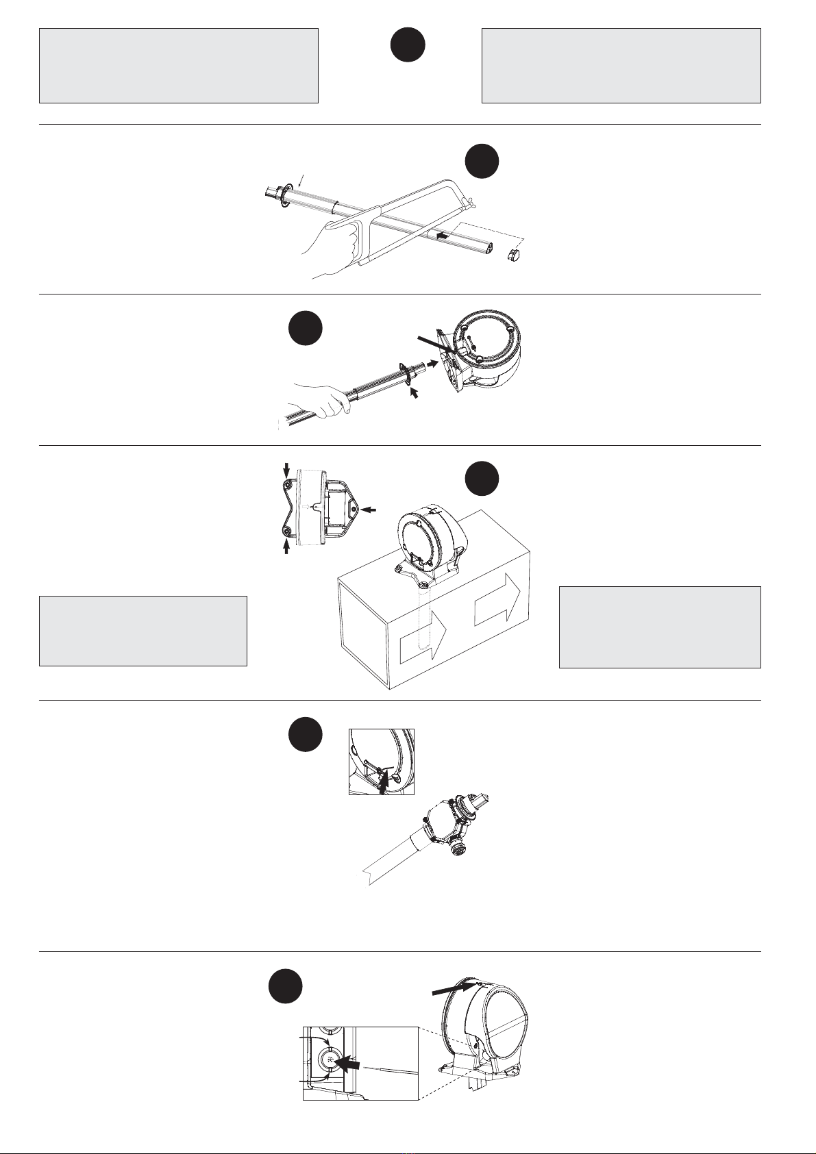
Montering av olika rör i olika kanalbredder. 8
Drill a hole
Ø 51 mm.
NOTE!
Håltagning
Ø 51 mm.
OBS!
Kanalbredd större än 0,6 m.
Venturiröret skall gå igenom hela kanalen.
Diameter of the duct bigger than 0,6 m.
The venturi pipe should penetrate the whole duct.
Håltagning Ø 38 mm
Drill a hole Ø 38 mm. Håltagning Ø 38 mm
Drill a hole Ø 38 mm.
Max kanalbredd 0,6 m.
Använd venturirör 0,6 m.
Kapa eventuellt till rätt längd.
Max diameter of the duct 0,6 m.
Use the venturi pipe 0,6 m.
Shorten the pipe, if necessary.
För kanaler mindre än 0,6 m används venturirör 0,6 m, standard.
För kanaler mellan 0,6 m och 1,4 m används venturirör 1,5 m.
För kanaler större än 1,4 m används venturirör 2,8 m.
For ducts with a ø of less than 0,6 m use the 0,6 m pipe, standard.
For ducts with a ø of between 0,6 m and 1,4 m use the 1,5 m pipe.
For ducts which are larger than 1,4 m use the 2,8 m pipe.
Kapa röret till rätt längd.
Sätt i ändpluggen.
Sätt på avslutnings-
tätningen.
Sätt på gummitätning
HFU204 som "lager".
Shorten the pipe to correct length.
Insert the end plug.
Put on the plastic end
gasket.
Put on the rubber
gasket, HFU204.
Röret max 30 mm utanför kanalen.
The venturi pipe shall not protrude more
than max 30 mm through the duct wall.
Fitting of pipes in ducts with different diameters.
Håltagning Ø 38 mm.
Drill a hole Ø 38 mm.
Håltagning Ø 38 mm.
Drill a hole Ø 38 mm. Vid montering i kanal utomhus används
isolerande skyddshuv/låda UG-COVER.
For outdoor location use protection
cover e.g. Calectro´s UG-COVER.
Isolermatta 100-200 mm används för att
täcka hela Uniguarden vid montering
på kallvind. Anvisningsskylt bör monteras.
Use insulation cover of 100-200 mm and
protect the entire Uniguard. A sign should
be used to show location of the detector.
Skylt
Sign
Extern LED som
larmindikering.
Remote LED
indication.
DOLD rökdetektor
HIDDEN smoke detector
Montering vid risk för kondensproblem,
t.ex. kallvind eller utomhus. 9
UG-beslaget levereras plant.
The UG-bracket is supplied flat.
UG-beslaget är lätt att böja/forma så att det
passar runda eller plana kanaler.
The UG-bracket can easily be bent or
shaped to fit circular or rectangular duct.
Håltagning
Ø 51 mm.
Drill a hole
Ø 51 mm.
Fäst beslagets
ben på kanalen.
Fix the bracket
on to the duct.
Rund kanal.
Circular duct.
Gummi-
tätning.
Rubber
gasket.
Isolerad, plan kanal.
Insulated rectangular duct.
Gummi-
tätning.
Rubber
gasket.
UG-beslag, rund eller isolerad plan kanal. 10
SLUTKONTROLL
• Kontrollera att riktningspilarna pekar i flödesriktningen.
• Kontrollera att pluggen till testhålet sitter i ordentligt.
• Kontrollera att flödesindikatorn visar på flöde (vippar).
Mounting in places where possible
condensation problems could arise, e.g.
cold attics or outdoor.
Med hjälp av beslaget kan kanal-
diametern vara så liten som 100 mm.
UG-bracket for circular or insulated
rectangular ducts.
Using the UG-bracket the diameter of
the duct can be as small as 100 mm.
FINAL CHECKS
• Check that the air flow direction arrows have the same direction
as the air flow in the duct.
• Check that the plastic plug of the test hole is properly mounted.
• Check that the flow indicator oscillates ensuring proper air flow
through the detector.
© 2014.04.29 Calectro AB HFE510
Enligt WEEE (Waste of Electrical and Electronic Equipment)
direktiv, skall produkten när den är förbrukad lämnas separat hos
ett härför avsett insamlingsställe och inte placeras bland osorterat
avfall. Alternativt returnera den till Calectro för återvinning.
!According to WEEE (Waste of Electrical and Electronic Equipment)
directive, you must at the end of life of the product dispose of it
separately at an appropriate collection point and not place it with
unsorted waste. Alternatively return it to Calectro for recycling. !

This manual suits for next models

1

Other CALECTRO Accessories manuals

CALECTRO CPS-A User manual

CALECTRO

CALECTRO CPS-A User manual

CALECTRO CPS-D-A User manual

CALECTRO

CALECTRO CPS-D-A User manual

CALECTRO CPS-D-A-9500 User manual

CALECTRO

CALECTRO CPS-D-A-9500 User manual

CALECTRO CPS-D-SW User manual

CALECTRO

CALECTRO CPS-D-SW User manual

CALECTRO CPS-24V User manual

CALECTRO

CALECTRO CPS-24V User manual

Popular Accessories manuals by other brands

Pfannenberg DTS series Operating and assembly instructions

Pfannenberg

Pfannenberg DTS series Operating and assembly instructions

PASCO PS-3217 Replacement instructions

PASCO

PASCO PS-3217 Replacement instructions

ipf electronic OT059176 manual

ipf electronic

ipf electronic OT059176 manual

VWR INCU-Line Premium instruction manual

VWR

VWR INCU-Line Premium instruction manual

AEB 1300 Assembly Instructions and Guarantee

AEB

AEB 1300 Assembly Instructions and Guarantee

AUREL MAG 4MHCS user manual

AUREL

AUREL MAG 4MHCS user manual

MS Sedco microStar manual

MS Sedco

MS Sedco microStar manual

Valeport miniIPS2 operating manual

Valeport

Valeport miniIPS2 operating manual

Eterna PIRFM360 installation guide

Eterna

Eterna PIRFM360 installation guide

Flybar Velocity owner's manual

Flybar

Flybar Velocity owner's manual

Verilux CleanWave VH03 manual

Verilux

Verilux CleanWave VH03 manual

Lexicon MC-12HD supplementary guide

Lexicon

Lexicon MC-12HD supplementary guide

PreCise Biometrics Precise 100 A user guide

PreCise Biometrics

PreCise Biometrics Precise 100 A user guide

SMaBiT COQON BWMWSV01 manual

SMaBiT

SMaBiT COQON BWMWSV01 manual

Tour Links Mini Link Setup manual

Tour Links

Tour Links Mini Link Setup manual

SUTO S 430 Instruction and operation manual

SUTO

SUTO S 430 Instruction and operation manual

Logitek ULTRA-VU Operation & service manual

Logitek

Logitek ULTRA-VU Operation & service manual

E+E Elektronik EE212 user manual

E+E Elektronik

E+E Elektronik EE212 user manual

manuals.online logo
manuals.online logoBrands
  • About & Mission
  • Contact us
  • Privacy Policy
  • Terms and Conditions

Copyright 2025 Manuals.Online. All Rights Reserved.