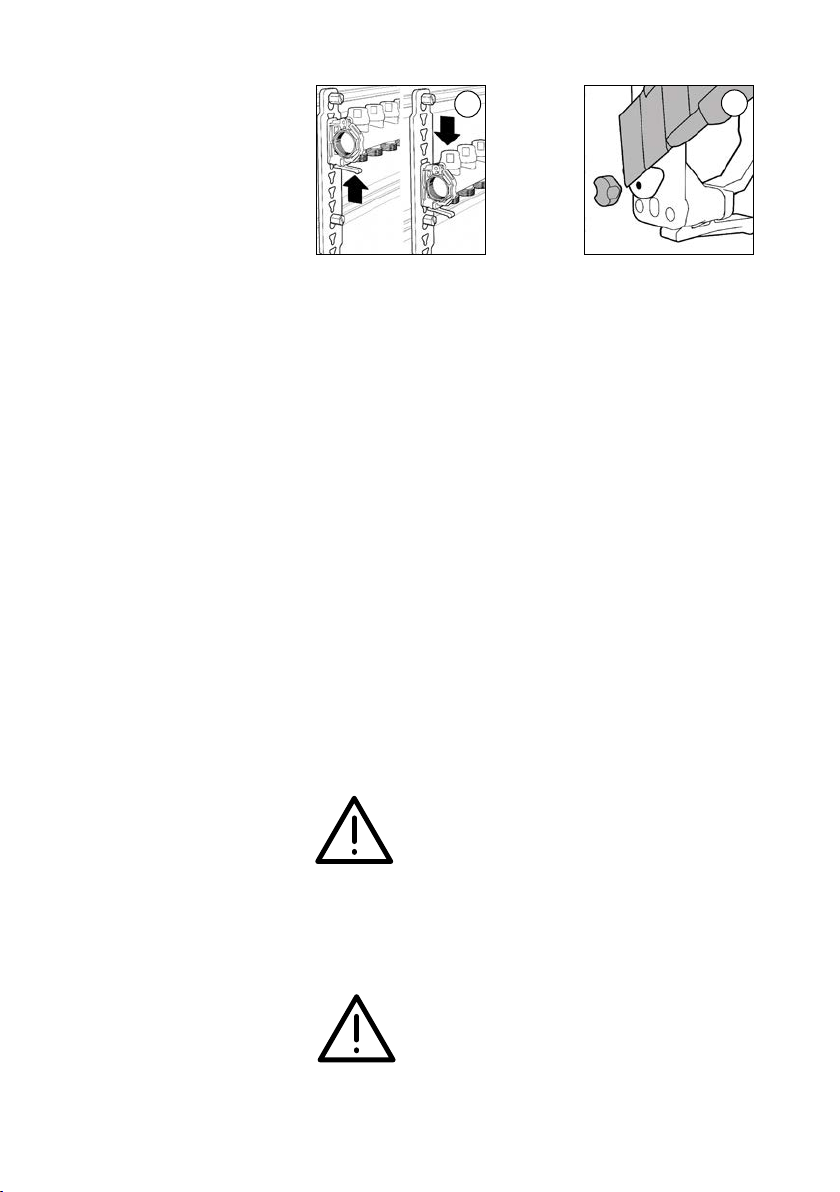
CALEFFI 664 Series User manual

Collettore di distribuzione per impianti a pannelli radianti
Distribution mani old or radiant panel systems
Verteiler ür Fußbodenheizungsanlagen
Collecteur de distribution pour installations de plancher chau ant
Colector de distribución para instalaciones de suelo radiante
Colector de distribuição para instalações de chão radiante
Collector voor vloerverwarmingsinstallaties
68483
1
www.caleffi.com
CALEFFI
664 series
Funzione
Function
Funktion
Fonction
Función
Função
Werking
Il collettore di distribuzione viene utilizzato per il controllo e la distribuzione del fluido
termovettore negli impianti di riscaldamento a pannelli radianti.
The distribution manifold is used for the control and distribution of thermal medium
in radiant panel heating systems.
Der Verteiler dient zur Kontrolle und Verteilung des Wärmevektors in
Fußbodenheizungsanlagen.
Le collecteur de distribution permet la distribution du fluide caloporteur, dans les
installations de plancher chauffant.
El colector de distribución controla el paso de fluido caloportador en las
instalaciones de calefacción por suelo radiante.
O colector de distribuição é utilizado para o controlo e a distribuição do fluido
termovector nas instalações de aquecimento por chão radiante.
De collector regelt en verdeelt de warmtegeleidende vloeistof in
vloerverwarmingsinstallaties.
Product range
© Copyright 2014 Caleffi
I
GB
Code Size Outlets
6646B1 1” 2
6646C1 1” 3
6646D1 1” 4
6646E1 1” 5
6646F1 1” 6
6646G1 1” 7
6646H1 1” 8
6646I1 1” 9
6646L1 1” 10
6646M1 1” 11
6646N1 1” 12
6646O1 1” 13
F
E
P
NL
D

Materials
Flow mani old
- body brass EN 1982 CB753S
Flow rate balancing valve
- stem and obturator PA
- seals EPDM
- knob ABS
- spring stainless steel
Return mani old
- body brass EN 1982 CB753S
Shut-o valve
- headwork brass EN 12164 CW614N
- obturator stem stainless steel
- obturator EPDM
- spring stainless steel
- seals EPDM
- knob ABS
Performance
Medium water, glycol solutions
Max. percentage of glycol 30%
Max. working pressure 6 bar
Working temperature range 5–60°C
LCD thermometer scale 24–48°C
Flow meter scale 0-5 l/min
Accuracy ±10%
Main connections 1” F (ISO 228-1)
Outlets 3/4” M - Ø 18
Centre distance 50 mm
2
Technical specifications
Hydraulic characteristics
Flow rate balancing valve fully open (MV)
Shut-off valve (SV)
Kv
1,10
4,10
Kv 0,01
110
410
1000
100
6p (mm w.g.)
200
50
500
900
800
700
600
60
70
80
90
120
140
160
180
250
300
350
400
450
10
1
2
0,5
5
9
8
7
6
0,6
0,7
0,8
0,9
1,2
1,4
1,6
1,8
2,5
3
3,5
4
4,5
6p (kPa)
10
20
12
14
16
18
25
30
35
40
45
0,1
0,2
0,12
0,14
0,16
0,18
0,25
0,3
0,35
0,4
0,45
10
20
0,5
1
2
5
0,2
2
0,1
Flow rate
(l/min) (m
3
/h)
MV SV
- Kv = flow rate in m3/h for a head loss of 1 bar
- Kv0,01 = flow rate in l/h for a head loss of 1 kPa

3
L’alloggiamento del collettore serie 664 nelle cassette di contenimento
risulta agevole ed in particolare se effettuato utilizzando la cassetta
Caleffi cod. 659..4.
Installing the 664 series manifold in inspection wall boxes is easy,
especially when using Caleffi box code 659..4.
Der Einbau des Verteilers der Serie 664 in die Verteilerschränke erfolgt
problemlos und ist bei Verwendung des Caleffi Verteilerschranks, Art.-
Nr. 659..4, besonders leicht auszuführen.
La fixation du collecteur série 664 dans les coffrets est simplifiée,
notamment pour le coffret Caleffi code 659..4
El alojamiento del colector serie 664 es particularmente sencillo con el
uso de la caja Caleffi cód. 659..4.
A inserção do coletor série 664 na caixa é simples, sobretudo, se for
utilizada a caixa Caleffi código 659...4.
De collector serie 664 kan gemakkelijk in inbouwkastenkasten worden
geplaatst, vooral als hiervoor de Caleffi inbouwkast art. 659.4 wordt
gebruikt.
Installazione
Installation
Installation
Installation
Instalación
Instalação
Installatie

4
Procedura di assemblaggio
zanche e montaggio collettori
Bracket assembly and manifold
installation procedure
Zusammenbau der
Wandhalterungen und Montage
der Verteiler
Procédure de fixation et de
montage des collecteurs
Procedimento de montagem
dos suportes e dos coletores
Ensambla e en las guías y
monta e de los colectores
Assemblageprocedure
draagbeugels en montage
collectoren
Inserire i perni dei ganci nelle sedi dei supporti procedendo prima dalla
parte più lunga, e successivamente, tramite rotazione, dalla parte più corta.
Insert the pins of the hooks in the relevant slots on the supports, starting with
the longer part then rotating the element and moving onto the shorter part.
Die Stifte der Haken in den Sitz der Halterungen einfügen zunächst am
längeren Teil und anschließend, nach entsprechender Drehung, am
kürzeren Teil.
Insérer les axes des crochets dans les érgots de l'étrier en mettant l’ergot
le plus gros dans la partie la plus grosse, puis l’ergot plus petit dans le
plus petit trou.
Inserte los pernos de los ganchos en las cavidades de los soportes. Introduzca
primero la parte más larga y después, con una rotación, la más corta.
Inserir os pernos dos ganchos nas sedes dos suportes, iniciando pela parte
mais longa e, depois, através de rotação, pela parte mais curta.
Steek de pennen van de haken in de behuizingen van de dragers, eerst
aan de lange kant en daarna, door ze te draaien, aan de korte kant.
12
Assemblaggio collettori - supporti - zanche in cassetta
Assembly of manifolds - supports - brackets inside the box
Zusammenbau Verteiler - Halterungen - Wandhalterungen im Verteilerschrank
Assemblage des collecteurs - étriers - supports en coffret
Ensamblaje de colectores - soportes - guías en la caja
Montagem dos coletores e suportes na caixa
Assemblage collectoren - dragers - draagbeugels in kast
(solution A) (solution B)
3A
4A
3B
4B

Note:
During wall installation, the brackets must be spaced in
accordance with the measurement between the two
octagonal profiles of the manifold, in which the supports
will be fixed. This allows precise coupling of the manifold,
supports and brackets.
The shut-o and regulation valves built into the
mani olds must not be used to shut o the medium
lowing towards the outside environment at
atmospheric pressure (i necessary, use the speci ic
screw plug, code 386500).
Le zanche sono predisposte anche per essere installate direttamente
a muro. Gli spessori possono essere asportati tramite un taglierino,
prima di procedere con l’installazione.
The brackets also offer the option of direct wall installation. The
spacers can be removed using a cutter before installation takes
place.
Die Struktur der Wandhalterungen erlaubt deren Installation auch
direkt an der Wand. Die Abstandhalter können vor der Installation mit
einem Messer entfernt werden.
Les supports de fixation sont prévus également pour une installation
murale. Les cales doivent être enlevées à l’aide d’un cutter, avant de
poursuivre l’installation.
Las guías pueden aplicarse directamente a la pared. Los
separadores se pueden quitar con una cuchilla, antes de comenzar
la instalación.
Os suportes também estão preparados para serem instalados
diretamente na parede. Os grampos podem ser removidos através de
um x-ato, antes de prosseguir com a instalação.
De draagbeugels zijn ook geschikt om direct aan de wand te worden
gemonteerd. De vulstukken kunnen met een mesje worden verwijderd
alvorens over te gaan tot montage.
5
56
Nota: Nell’installazione a muro, è necessario distanziare le
zanche secondo la misura che intercorre tra i due profili
ottagonali del collettore, nei quali andranno fissati i
supporti. Questo per consentire un accoppiamento
preciso tra collettore, supporti e zanche.
Le valvole di intercettazione e di regolazione
incorporate nei collettori non possono essere
utilizzate per intercettare il luido verso l’ambiente
esterno, a pressione atmos erica (in caso di necessità
utilizzare l’apposito disco a tappo, cod. 386500).

Hinweis:
Bei der Wandinstallation ist es erforderlich, die
Wandhalterungen mit einem Abstand in Entsprechung zum
Maß zwischen den zwei achteckigen Profilen des
Verteilers zu positionieren, in welchen die Halterungen
befestigt werden. Dadurch soll eine tadellose Verbindung
zwischen Verteiler, Halterungen und Wandhalterungen
gewährleistet werden.
Die in den Verteilern integrierten Absperr- und
Regelventile können nicht dazu verwendet werden,
den Durch luss zur Außenumgebung mit
Atmosphärendruck abzusperren (bei Bedar die
spezielle Blindkappe, Art.-Nr. 386500, verwenden).
Remarque : Pour une installation au mur, il est nécessaire de
distancer les supports selon les deux profils octogonaux
des collecteurs, dans lesquels seront fixés les étriers.
Ceci permettra un accouplement précis entre les
collecteurs, les étriers et les supports.
Les vannes d’arrêt et de réglage incorporées aux
collecteurs ne peuvent pas être utilisées pour arrêter
le luide vers l’ambiance exterieure, à la pression
atmosphérique (dans ce cas utiliser le bouchon avec
écrou pour dérivations des collecteurs code 386500).
Nota: Para el montaje mural, es necesario separar las guías en
función de la distancia que hay entre los dos perfiles
octogonales del colector, a los cuales se fijarán los
soportes. De esta forma se obtiene un acoplamiento
preciso entre el colector, los soportes y las guías.
Las válvulas de corte y de regulación incorporadas
en los colectores no se pueden utilizar para cerrar
el paso de luido hacia el ambiente exterior a
presión atmos érica (en caso de necesidad, utilice
el disco tapón cód. 386500).
6
Nota:
Ao instalar na parede, é necessário distanciar os suportes
de acordo com a medida existente entre os dois perfis
octogonais do coletor, nos quais serão fixados. Isto permite
o encaixe preciso do coletor e dos suportes.
As válvulas de interceção e de regulação
incorporadas nos coletores não podem ser utilizadas
para cortar o luido em direção ao exterior, com
pressão atmos érica (caso seja necessário, utilizar o
tampão com porca apropriado, código 386500).
Opmerking:
Bij montage tegen de wand moeten de draagbeugels
een onderlinge afstand hebben afhankelijk van de
maat tussen de twee achthoekige profielen van de
collector, waarin de dragers moeten worden
bevestigd. Dit maakt een nauwkeurige koppeling
tussen de collector, dragers en draagbeugels mogelijk.
De in de collectoren ingebouwde a sluit- en
regelkranen kunnen niet gebruikt worden om de
vloeisto stromen naar de rest van de installatie met een
atmos erische druk tegen te houden (gebruik indien
nodig de speciale a sluitdop met schij , art. 386500).

b)Ad impianto funzionante, regolare la
portata di progetto agendo
manualmente sulla ghiera di
regolazione (1).
Il valore della portata viene indicato
dal movimento verticale del disco
indicatore rosso (2).
b)While the system is running, manually
adjust the design flow rate using the
adjustment locking nut (1). The flow
rate value is indicated by the vertical
movement of the red indicator disc (2).
b) Bei laufender Anlage die projektbezogene Durchflussmenge durch
manuelles Betätigen der Einstellschraube (1) regeln. Der Wert der
Durchflussmenge wird an der vertikalen Bewegung der roten
Anzeigescheibe (2) ermittelt.
b) Pendant le fonctionnement de l'installation, régler le débit en
actionnant manuellement la bague de réglage (1). La valeur du
débit est indiquée par le mouvement vertical du disque indicateur
rouge (2)
b) Con la instalación en marcha, ajuste el caudal de diseño mediante
el anillo de regulación (1). El valor del caudal se indica mediante el
movimiento vertical del disco rojo (2).
b) Com a instalação em funcionamento, regular manualmente o
caudal de projeto, utilizando a rosca de regulação (1). O valor do
caudal é indicado pelo movimento vertical do disco indicador
vermelho (2).
b) Regel bij werkende installatie het ontwerpdebiet door de regelmoer
(1) met de hand te verstellen. De debietwaarde wordt aangegeven
door de verticale beweging van de rode indicatieschijf (2)
1
2
7
Regolazione della portata
Flow rate ad ustment
Regelung der
Durchflussmenge
Réglage du débit
Regulación del caudal
Regulação do caudala
Debietregeling
a) Estrarre manualmente il coperchio
di protezione taratura bianco dal
flussometro.
a)
Manually remove the white setting
protection cover from the flow meter
a)
Den weißen Einstellungsschutzdeckel
mit der Hand vom
Durchflussmesser abziehen.
a) Extraire à la main le couvercle de
protection rouge du débitmètre.
a) Extraiga manualmente del caudalímetro la tapa blanca de
protección de la calibración.
a) Extrair manualmente a tampa branca de proteção da regulação do
caudalímetro.
a) Neem het witte deksel ter bescherming van de afstelling van de
debietmeter met de hand weg.

c)
Quando il disco indicatore rosso (2) si
posiziona sul valore di portata
desiderata, riportare l’indicatore
esterno (3) in corrispondenza del
disco indicatore interno (2).
Riposizionare il coperchio protettivo
eseguendo la procedura inversa
descritta al punto a).
c) When the red indicator disc (2) is
positioned on the desired flow
rate value, set the external indicator
(3) in line with the internal indicator
disc (2). Place again the protection
cover, carrying out the procedure
described in point a) in reverse.
c) Erreicht die rote Anzeigescheibe
(2)
den gewünschten Wert der
Durchflussmenge, ist die äußere Anzeige auf die Höhe
(3)
der
inneren Anzeigescheibe zu positionieren
(2)
. Den Schutzdeckel
wieder anbringen; hierzu in umgekehrter Reihenfolge zur
Beschreibung unter Punkt a vorgehen.
c) Lorsque le disque indicateur rouge (2) est placé sur la valeur de
débit souhaitée, replacer l'indicateur externe (3) au niveau du
disque indicateur interne (2). Replacez le couvercle de protection
en inversant la procédure décrite au point a).
c) Cuando el disco indicador rojo (2) se sitúe en el valor de caudal
deseado, ponga nuevamente el indicador externo (3) en
correspondencia con el disco indicador interno (2). Coloque la
tapa de protección, procediendo en orden contrario al indicado en
el punto a).
c) Quando o disco indicador vermelho (2) se posicionar no valor do
caudal desejado, voltar a colocar o indicador externo (3) em
correspondência com o disco indicador interno (2). Voltar a
colocar a tampa de proteção, realizando o procedimento inverso
descrito no ponto “a”.
c) Wanneer de rode indicatieschijf (2) op de gewenste debietwaarde
staat, moet de externe indicator (3) bij de interne indicatieschijf
worden gebracht (2). Plaats het beschermdeksel terug door de bij
punt a beschreven procedure in omgekeerde volgorde uit te voeren.
d) Estrarre il coperchio di protezione vedi punto a) “Regolazione
della portata”
d) Remove the protection cover see point a). "Flow rate adjustment"
d) Den Schutzdeckel abziehen siehe a. „Regelung der
Durchflussmenge“.
d) Extraire le couvercle de protection voir a. « Réglage du débit »
d) Quite la tapa de protección vea el punto a) "Regulación del
caudal".
d) Extrair a tampa de proteção consultar o ponto “a”. “Regulação do
caudal”.
d) Neem het beschermdeksel weg zie a. 'Debietregeling'
8
3
Pulizia del flussometro
Cleaning the flow meter
Reinigung des
Durchflussmessers
Nettoyage du débitmètre
Limpieza del caudalímetro
Limpeza do caudalímetro
Reiniging van de debietmeter

e) Intercettare il circuito di derivazione del flussometro da pulire, sia sul
collettore di mandata che in quello di ritorno avvitare a battuta le
manopole (1) e (4).
e) Shut-off the flow meter outlet circuit you wish to clean, at both the
flow and return manifolds fully tighten knobs (1) and (4).
e) Den Abgangskreislauf des zu reinigenden Durchflussmessers
absperren, sowohl am Verteiler des Vorlaufs als auch an
demjenigen des Rücklaufs hierzu die Handräder (1) und (4) bis
zum Anschlag einschrauben.
e) Fermer la boucle de plancher du débitmètre à nettoyer, à la fois sur
le collecteur de départ que sur celui de retour visser les poignées
jusqu'en butée (1) et (4).
e) Corte el flujo en el circuito de salida del caudalímetro que desee
limpiar, tanto en el colector de ida como en el de retorno. Para ello,
enrosque a tope los pomos (1) y (4).
e) Intercetar o circuito de derivação do caudalímetro a limpar, quer no
coletor de ida, quer no de retorno, e apertar totalmente os
manípulos (1) e (4).
e) Sluit het afgetakte circuit van de te reinigen debietmeter zowel op
de toevoercollector als op de retourcollector af draai de knoppen
(1) en (4) volledig aan.
f)
Svitare l’indicatore in plastica (5)
trasparente con una chiave a brugola
da 8 mm, mantenendo ferma la
manopola di regolazione con una
chiave esagonale da 22 mm (6).
f) Unscrew the transparent plastic indicator (5) using a 8 mm
allen key, holding the adjustment knob still using a 22 mm
hexagonal key (6)
f)
Die Anzeige aus durchsichtigem Kunststoff (5) mit einem 8 mm
Innensechskantschlüssel ausschrauben; hierbei das
Einstellhandrad mit einem 22 mm Sechskantschlüssel (6) festhalten.
f) Dévisser l'indicateur en plastique (5) transparent avec une clé Allen
8 mm, en maintenant fermement la bague de réglage avec une clé
hexagonale de 22 mm (6)
f) Desenrosque el indicador de plástico (5) transparente con una llave
Allen de 8 mm, sujetando el pomo de regulación con una llave
hexagonal de 22 mm (6).
5
6
1
4
9

f) Desapertar o indicador em plástico transparente (5) com uma
chave Allen de 8 mm, mantendo fechado o manípulo de regulação
com uma chave hexagonal de 24 mm (6).
f) Draai de doorzichtige plastic indicator (5) los met een inbussleutel
van 8 mm en houd daarbij de regelknop vast met een
zeskantsleutel van 24 mm (6)
g) Effettuare l’operazione di pulizia a
secco interna dell’indicatore con un
attrezzo apposito. Riposizionare
l’indicatore con operazione inversa
a quella del punto f). Aprire la valvola
di intercettazione (4) del collettore di
ritorno. Eseguire le operazioni di
regolazione della portata sul valore
indicato dall’indicatore esterno,
riportate nella sezione “Regolazione
della portata”. Ricambio cod. R69913.
g) Perform a dry cleaning of the inside of the indicator using a
suitable tool. Place again the indicator, carrying out the procedure
described in point f) in reverse. Open the return manifold shut-off
valve (4). Adjust the flow rate to the value indicated by the external
indicator, as described in the "Flow rate adjustments" section.
Spare part code R69913.
g) Den Innenbereich der Anzeige mit geeignetem Werkzeug reinigen.
Die Anzeige wieder anbringen; hierzu in umgekehrter Reihenfolge
zur Beschreibung unter Punkt f) vorgehen. Das Absperrventil (4)
des Rücklauf-Verteilers öffnen. Die im Abschnitt „Regelung der
Durchflussmenge“ beschriebenen Schritte ausführen, um die
Durchflussmenge auf den Wert zu regeln, der von der äußeren
Anzeige angegeben wird. Ersatzteil Art.-Nr. R69913.
g) Nettoyer l'intérieur de l'indicateur avec un outil approprié. Remettre
en place l'indicateur en procédant en sens inverse du point f).
Ouvrir la vanne d'arrêt (4) du collecteur de retour. Régler le débit
sur la valeur indiquée par l'indicateur extérieur, en effectuant les
opérations indiquées dans la section « Réglage du débit.» Pièce
détachée code R69913.
g) Limpie el indicador por dentro con un utensilio adecuado. Monte
el indicador, procediendo en orden contrario al indicado en el
punto f). Abra la válvula de corte (4) del colector de retorno. Ajuste
el caudal al valor señalado por el indicador externo, como se
indica en el apartado "Regulación del caudal". Recambio
cód. R69913.
g) Limpar o interior do indicador através da utilização de ferramenta
adequada. Voltar a colocar o indicador através do procedimento
inverso descrito no ponto “f”. Abrir a válvula de interceção (4) do
coletor de retorno. Efetuar as operações de regulação do caudal
no valor indicado pelo indicador externo, mencionadas na secção
“Regulação do caudal”. Peça de substituição código R69913.
g) Reinig de binnenkant van de indicator met een speciaal
gereedschap. Plaats de indicator weer door de werkzaamheid in
omgekeerde volgorde als bij punt f) uit te voeren. Open de afsluiter
(4) van de retourcollector. Stel het debiet af op de waarde die door
de externe indicator wordt aangegeven. Deze werkzaamheden zijn
beschreven in het deel 'Debietregeling'. Vervangingsonderdeel
art. R69913.
10

11
Il collettore deve essere installato da un installatore qualificato in accordo con i regolamenti
nazionali e/o i relativi requisiti locali.
Se i collettori non sono installati, messi in servizio e manutenuti correttamente secondo le
istruzioni contenute in questo manuale, possono non funzionare correttamente e porre
l’utente in pericolo.
Assicurarsi che tutta la raccorderia di collegamento sia a tenuta idraulica.
Nella realizzazione delle connessioni idrauliche, prestare attenzione a non sovrasollecitare
meccanicamente le filettature. Nel tempo si possono produrre rotture con perdite
idrauliche a danno di cose e/o persone.
Temperature dell’acqua superiori a 50°C possono provocare gravi ustioni.
Durante l’installazione, messa in servizio e manutenzione dei collettori, adottare gli
accorgimenti necessari affinché tali temperature non arrechino pericolo per le persone.
Lasciare il presente manuale ad uso e servizio dell’utente
The manifold must be installed by a qualified technician in accordance with national
regulations and/or relevant local requirements.
If the manifolds are not installed, commissioned and maintained correctly, according to the
instructions contained in this manual, they may not function properly and could endanger
the user.
Make sure that all connection fittings are watertight.
When making hydraulic connections, make sure that threaded connections are not
mechanically overstressed. Over time this may result in breakages with consequent water
losses which could cause harm to property and/or people.
Water temperatures higher than 50°C may cause severe burns.
During installation, commissioning and maintenance of the manifold, take the necessary
precautions to ensure that these temperatures do not endanger people.
Leave this manual at the user's disposal
Der Verteiler muss durch einen qualifizierten Fachmann gemäß den nationalen und/oder
lokalen einschlägigen Vorschriften installiert werden.
Nicht genau nach den Anweisungen dieser Anleitung installierte, in Betrieb genommene
oder gewartete Verteiler können unter Umständen nicht korrekt funktionieren und eine
Gefahr für den Benutzer darstellen.
Die Dichtheit sämtlicher Anschlussverschraubungen überprüfen.
Bei der Ausführung hydraulischer Anschlüsse ist darauf zu achten, die Gewinde nicht
mechanisch überzubeanspruchen. Im Lauf der Zeit können Beschädigungen mit
Leckverlusten auftreten, die eine Gefahr für Personen und/oder Gegenstände darstellen.
Wassertemperaturen über 50°C können zu schweren Verbrühungen führen.
Während der Installation, der Inbetriebnahme und der Wartung der Verteiler sind die
notwendigen Vorkehrungen zu treffen, damit durch diese Temperaturen keine Personen
gefährdet werden.
Diese Anleitung ist dem Benutzer auszuhändigen
Le collecteur doit être installé par un technicien qualifié et conformément aux règlements
nationaux et/ou aux prescriptions locales.
Si les collecteurs ne sont pas installés, mis en service et entretenus correctement selon les
instructions fournies dans ce manuel, ils risquent de ne pas fonctionner correctement et
de représenter une source de danger.
S'assurer que tous les raccordements sont étanches.
Dans la réalisation des raccordements hydrauliques, faire attention à ne pas forcer
mécaniquement sur les raccords du collecteur. Un serrage excessif peut provoquer à
terme une rupture entraînant des fuites et causer des dommages aux biens et/ou aux
personnes.
Une température supérieure à 50°C peut provoquer de graves brûlures.
Durant l'installation, la mise en service et l'entretien du collecteur, mettre en oeuvre les
moyens nécessaires pour éviter que de telles températures mettent en danger les
utilisateurs.
Laisser ce manuel à disposition de l'utilisateur
Sicurezza
Safety
Sicherheit
Sécurité
Seguridad
Segurança
Veiligheid

El colector debe ser instalado por un técnico matriculado y de conformidad con las
reglamentaciones pertinentes.
Si la instalación, la puesta en servicio y el mantenimiento no se realizan de acuerdo con lo
indicado en este manual, los colectores pueden no funcionar correctamente y poner al
usuario en peligro.
Controlar que todos los racores sean perfectamente estancos.
Al realizar el conexionado hidráulico, tener cuidado de no forzar las roscas. Con el tiempo
podrían verificarse pérdidas de agua con los consiguientes daños materiales o
personales.
El agua a más de 50°C puede causar quemaduras graves.
Durante la instalación, la puesta en servicio y el mantenimiento de los colectores, tomar
las precauciones necesarias para que dichas temperaturas no supongan ningún peligro
para los usuarios.
Entregar este manual al usuario
O colector deve ser instalado por um instalador qualificado de acordo com a
regulamentação nacional e/ou os respectivos requisitos locais.
Se os colectores não forem instalados, colocados a funcionar e mantidos correctamente
segundo as instruções contidas neste manual, poderão não funcionar de modo correcto
e colocar o utilizador em perigo.
Certificar-se que todas as uniões de ligação tenham vedação hidráulica.
Ao efectuar as ligações hidráulicas, ter em atenção para não forçar mecanicamente a
parte roscada. Com o tempo, poderão ocorrer rupturas com perdas de água que podem
causar danos materiais e/ou pessoais.
Temperaturas da água superiores a 50°C podem provocar queimaduras graves.
Durante a instalação, a colocação em funcionamento e a manutenção dos colectores,
adoptar as precauções necessárias para que essas temperaturas não coloquem as
pessoas em perigo.
Este manual deve icar à disposição do utilizador
De collector moet door een bevoegde installateur geïnstalleerd worden, overeenkomstig
de nationale regelgeving en/of de plaatselijke richtlijnen.
Indien de collectoren niet volgens de instructies in deze handleiding geïnstalleerd, in
werking gesteld en onderhouden worden, kan de werking ervan verstoord worden en zo
gevaar voor de gebruiker opleveren.
Zorg ervoor dat alle aansluitingen waterdicht zijn.
Let er bij het tot stand brengen van de hydraulische aansluitingen op dat de schroefdraden
niet mechanisch overbelast worden. Dit om na verloop van tijd waterverlies met schade
aan zaken en/of letsel van personen te voorkomen.
Watertemperaturen van boven de 50°C kunnen ernstige brandwonden veroorzaken.
Neem tijdens de installatie, de inwerkingstelling en het onderhoud van de collectoren de
nodige voorzorgsmaatregelen in acht, zodat deze temperaturen geen gevaar voor
personen kunnen vormen.
Gelieve de handleiding beschikbaar te stellen aan de gebruiker
12
Other manuals for 664 Series
1
This manual suits for next models
12
Other CALEFFI Digital Manifold manuals