9
Phenomenex
l
WEB: www.phenomenex.com
Getting Started
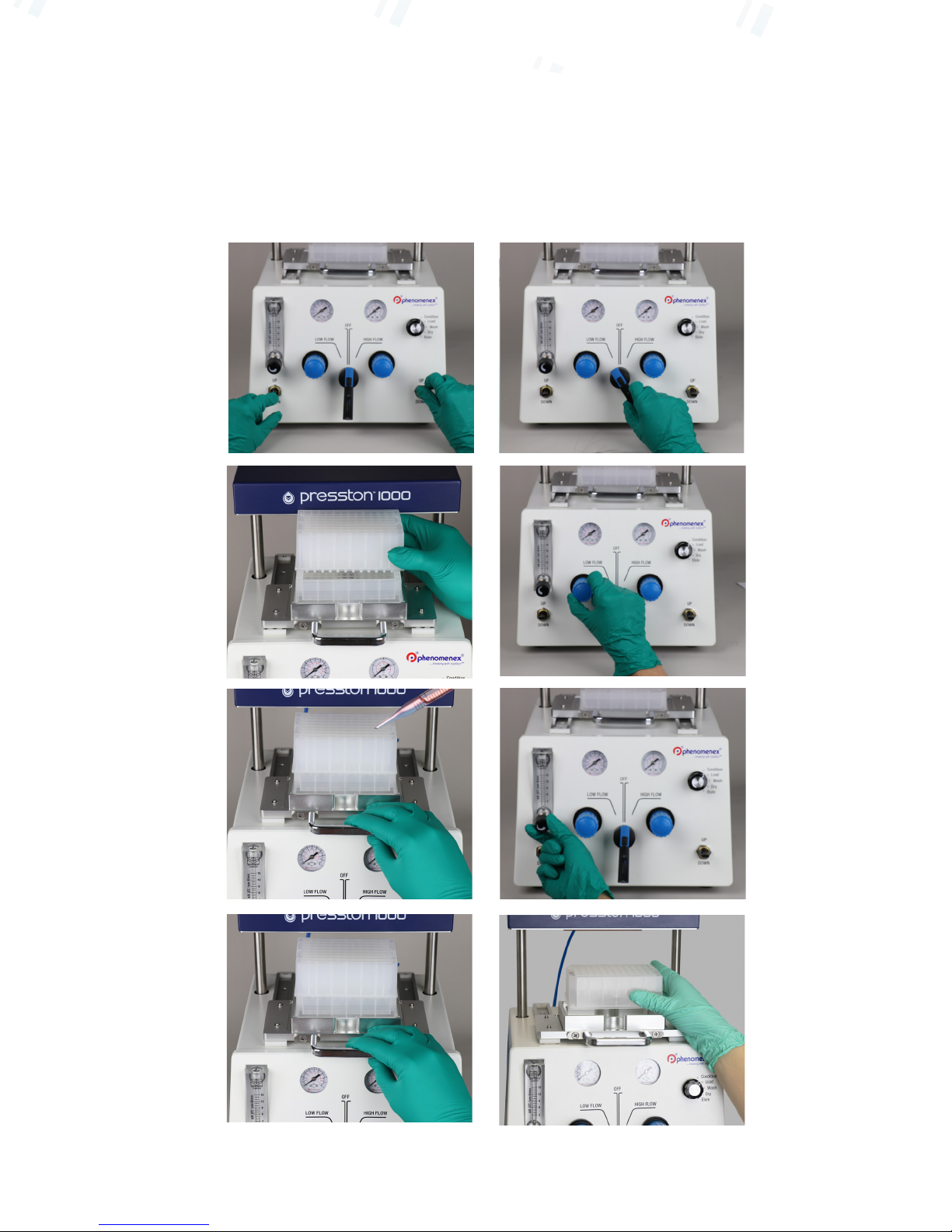
Refer to Figure 6 for images to help with the operation of Presston 1000
1. Ensure that the FLOW PATH SWITCHER is in the off position.
2. Turn on the gas and adjust the pressure from the GAS SOURCE to 0.5 MPa (72 psi) and adjust the black
knob on top of the GAS REGULATOR so that the pressure is between 0.3-0.5 MPa (43-72 psi). If the GAS
REGULATOR shows no change in pressure, continue to turn the black knob until the regulator pathway is
opened. The GAS REGULATOR ensures that the pressure inside the Presston 1000 does not exceed the
pressure capacity of the manifold. Note: If the sample is viscous and needs more pressure, adjust the gas
supply pressure to 0.7 MPa (101 psi) and adjust the GAS REGULATOR to 0.5-0.7 MPa (72-101 psi).
3. Place both hands on the MANIFOLD POSITIONING SWITCHES and move into the UP position. The
MANIFOLD SHIELD will move up. Note: both switches must be flipped up at the same time and the gas
source must be flowing in order to move the manifold shield (Figure 6.1).
4. Once the MANIFOLD SHIELD has stopped moving, pull out the LOCATOR PLATE and set the
appropriate number of manifold spacers (1 or 2 depending on the height of 96-well plates and waste
trough) onto the locator plate.
Set the waste container trough on top of the manifold spacer(s) and then
proceed to place the 96-well plate that will be used for the extraction on top of the waste collection trough
(Figure 6.2).
5. Add samples or solvents into the wells of the plate (Figure 6.3) and push the locator plate back under the
MANIFOLD SHIELD (Figure 6.4).
6. Place both hands on the MANIFOLD POSITIONING SWITCHES and move into the DOWN position.
The MANIFOLD SHIELD will move down. Note: both switches must be flipped down at the same time
and the gas source must be flowing in order to move the manifold shield.
7. Turn the FLOW PATH SWITCHER to either LOW PRESSURE REGULATOR or HIGH-PRESSURE
REGULATOR (Figure 6.5) and adjust to the desired pressure (Figure 6.6). Note: Use low flow rate for
condition, equilibrate, load, wash, dry, and elution steps; high flow rate for dry down steps and very
viscous samples.
8. If neccessary, use the GAS FLOW METER as a fine tune flow adjustment feature and slowly adjust to the
proper pressure (Figure 6.7).
9. Once liquid has cleared the sorbent, proceed to turn the FLOW PATH SWITCHER into the OFF position
and repeat steps 3-8 for the next step in the SPE protocol.
10. Before the elution step, take out the waste container and replace with a collection plate and proceed to
start with steps 5-8 again (Figure 6.8).
11. Don’t forget to switch the SPE PROCEDURE INDICATOR after performing each step.
12. When extractions are complete, ensure that the system is depressurized by turning the
GAS REGULATOR VALVES to the left (counterclockwise).
Operation