Warmup WHS-M-S3-Series User manual

1
-Kv-
01 310
6
120
20 30
°C
0
10
20
30
40
50
80
70
60
°F
32
50
70
90 110
130
150
170
Hydronic
Heating System
IMPORTANT!
Please read this manual before
attempting to install your Warmup
product. Complete and submit your
warranty form online at
www.warmup.co.uk
0345 345 2288
TechnicalHelpline
Installation Manual
WHS-M-S3-Series Manifolds

Experience MyHeating™
Download now for iOS and Android
Easy to use
Simple and secure
set up with 24/7
support
Unique to Warmup:
Natural Language Programming™
Programming that speaks your language
Please scan the QR code
for more information
The world’s best-selling floor heating brand™
Over 2 million installations in
more than 60 countries
EasySwitch™
Always on the best
tari, automatically
SmartGeo™
Smarter geo-fencing.
Reduce energy usage
by up to 25%

3
Quick Install Guide........................................................................... 4
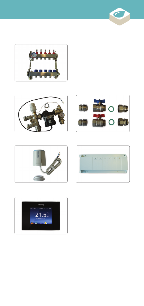
Components Available for Installation ........................................ 6
Do’s & Don’ts...................................................................................... 7
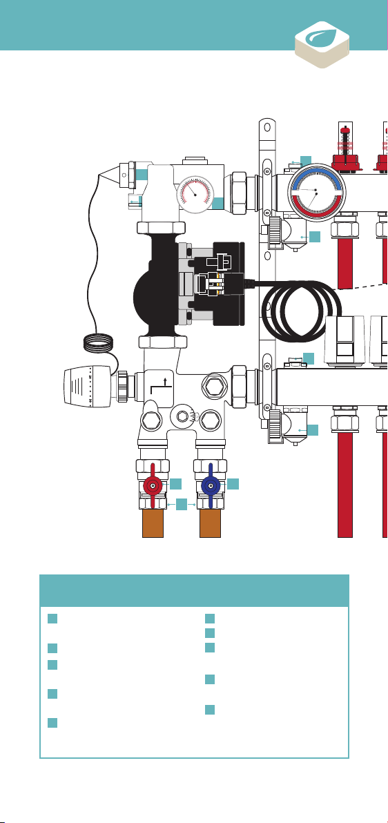
Overview ............................................................................................ 8
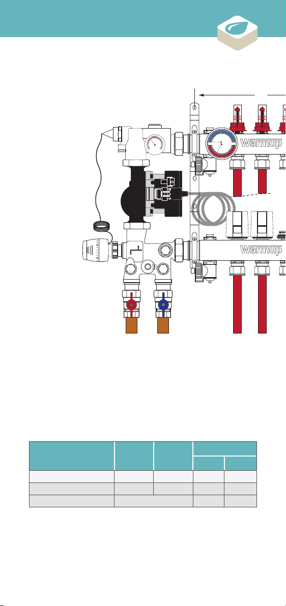
Dimensions...................................................................................... 10
Step 1 - Location Considerations .............................................. 12
Step 2 - Assembly.......................................................................... 13
Step 3 - Circuit Purging & Filling................................................. 18
Step 4 - Pressure Testing ............................................................ 20
Step 5 - Circuit Balancing............................................................ 22
Step 6 - Actuator Mounting......................................................... 24
Step 7 - Circulator Mode Setting................................................ 25
Step 8 - Capillary Thermostat Mounting.................................. 26
Step 9 - Temperature Settings.................................................... 27
Step 10 - Initial Heating Cycle .................................................... 28
Troubleshooting ............................................................................. 30
Layout Plan...................................................................................... 33
Commissioning Log....................................................................... 34
Warranty........................................................................................... 36
Technical Specifications ............................................................... 38
WARNING
Your Warmup® Underfloor heating system has been designed so that
installation is quick and straight forward, but as with all electrical
systems, certain procedures must be strictly followed. Please
ensure that you have the correct heater(s) for the area you wish
to heat. Warmup plc, the manufacturer of the Warmup® DCM-Pro
System, accepts no liability, expressed or implied, for any loss or
consequential damage suered as a result of installations which in
any way contravene the instructions that follow.
It is important that before, during and aer installation that all
requirements are met and understood. If the instructions are
followed, you should have no problems. If you require help at any
stage, please contact our helpline.
You may also find a copy of this manual, wiring instructions and other
helpful information on our website:
www.warmup.co.uk
Contents

4
-Kv-
01 310
6
120
°C
0
10
20
30
40
50
80
70
60
°F
32
50
70
90 110
130
150
170
-Kv-
01 310
6
120
20 30
°C
0
10
20
30
40
50
80
70
60
°F
32
50
70
90 110
130
150
170
-Kv-
01 310
6
120
°C
0
10
20
30
40
50
80
70
60
°F
32
50
70
90 110
130
150
170
-Kv-
01 310
6
120
°C
0
10
20
30
40
50
80
70
60
°F
32
50
70
90 110
130
150
170
-Kv-
01 310
6
120
°C
0
10
20
30
40
50
80
70
60
°F
32
50
70
90 110
130
150
170
Quick Install Guide - Please also read the full instructions
that follow this page.
•Connect the WHS-M-S3-
VALVES, isolation valve kit.
•Connect the primary supply
pipes to the manifold,
ensuring that only valves
operated by the UFH can
interrupt the supply
•Purge and fill the circuits.
•Assemble and connect the
WHS-M-S3-MIX, mixing unit
(if used).
•Identify a suitable location,
and mount the manifold.
•Connect the secondary
pipework, ensuring to record
circuit lengths.
1
3
5
4
2
6
Quick Install Guide

5
-Kv-
01 310
6
120
°C
0
10
20
30
40
50
80
70
60
°F
32
50
70
90 110
130
150
170
0
5
10
15
30
25
20
0psi
bar
45
120
190 260
320
435
420
0
5
10
15
30
25
20
0psi
bar
45
120
190 260
320
435
420 60
0
5
10
15
30
25
20
0psi
bar
45
120
190 260
320
435
420 45 15
0
5
10
15
30
25
20
0psi
bar
45
120
190 260
320
435
420
-Kv-
01 310
6
120
20 30
°C
0
10
20
30
40
50
80
70
60
°F
32
50
70
90 110
130
150
170
-Kv-
01 310
6
120
20 30
°C
0
10
20
30
40
50
80
70
60
°F
32
50
70
90 110
130
150
170
-Kv-
01 310
6
120
20 30
°C
0
10
20
30
40
50
80
70
60
°F
32
50
70
90 110
130
150
170
34
Location of Leak Action Taken Location of Fitting
if Repaired
Passed Pressure
Test ?
Yes / No
Yes / No
Yes / No
Yes / No
I
n
nam
me
of
c
com
mp
an
n
ny
hereby declare that the UFH system has been installed and fully commissioned in
accordance with the guidelines set out within this installation manual
Signed: Date:
Plumber Electrician
Name: Name:
Company: Company:
Address: Address:
Postcode: Postcode:
Tel: Tel:
Email: Email:
Project Ref: Project Ref:
Circuit
Number
Room
Served
Zone
Number
Circuit
Length
Circuit Flow
Rate (l/min)
Pressure test
passed?
1
2
3
4
5
6
7
8
9
10
11
12
Installer Details
Manifold
Location
Temperature
Setting
Purged and
Filled ?
Pressure Test
Completed ?
Circuits
Balanced ?
Fully
Operational
Installation Details
Declaration
NOTE:Failure to pre sent this commis sioning log (accurate ly completed wit h
declaration signed), up on request, w ill void system war ranty.
Commissioning Log
•Make the electrical
connections to the circulator,
setting it to operate on
Constant Pressure Curve 3.
•Install actuators.
•Record all install information
on the commissioning log
found in the back of this guide.
•Pressure test the system.
•Balance the secondary
circuits.
•Install thermostatic actuator,
its capillary sensor and set the
secondary flow temperature
(if used).
7
9
11
8
10
12
Quick Install Guide

6
Components available from Warmup
Warmup Thermostat
WHS-M-S3-VALVES
WHS-C-B-MASTER01
WHS-M-S3-XX
WHS-M-S3-MIX
WHS-M-S3-02
WHS-M-S3-03
WHS-M-S3-04
WHS-M-S3-05
WHS-M-S3-06
WHS-M-S3-07
WHS-M-S3-08
WHS-M-S3-09
WHS-M-S3-10
WHS-M-S3-11
WHS-M-S3-12
WHS-M-S3-ACT230
Components Available

7
Ensure the WHS-M-S3-XX manifold is mounted to a structurally
sound wall capable of bearing the load imposed by the manifold.
Precautions should be taken to reduce the risk of damaging any
services within the walls when drilling.
Keep the area clean and clear, reducing the risk of foreign bodies
entering the system.
Use suitable pipe cutters to ensure a square, clean cut is made to
the pipework.
Ensure all data is fully recorded on the commissioning log.
Ensure, where the system is subject to the risk of freezing, the
system is purged or a suitable antifreeze, such as Glycol (up to
30% by volume) is used.
Do not exceed specification - failure to do so will void the
warranty.
Do not use excessive force when adjusting flow gauges.
Do not guess the flow rates or temperature settings, as this
will waste energy, and potentially incur higher running costs
compared to a correctly designed and commissioned system.
Do’s & Don’ts
DO
DON’T

8
WHS-M-S3-MIX Mixing unit
1
2
3
4
5
Capillary Thermostat -
Sensor
Circulator Isolation Valve
Thermometer -
Secondary Flow
Grundfos UPM3
25/70 - 130 Circulator
Capillary Thermostat -
Actuator
6
7
8
9
10
Secondary by-pass
Primary by-pass
Primary Isolation Valve
- Flow
Primary Isolation Valve -
Return
Primary Supply Adaptors
1”G to 22mm
3
4
5
7
6
9
10
8
1
13
13
14
17
17
2
Overview
-Kv-
01 310
6
120
20 30
°C
0
10
20
30
40
50
80
70
60
°F
32
50
70
90 110
130
150
170

9
11 17
12 18
13 19
14 20
15
21
16
22
WHS-M-S3-08 Manifold assembly
1 - 5 l/min Flowmeter
Flowmeter Locking Cap
Manual Air Vent
Thermomanometer
Flow Arm
End Caps
Fill/Drain Valve
Mounting Brackets
Electrothermic Actuator
Collar
Commissioning Cap
Return Arm
-Kv-
01 310
6
120
20 30
°C
0
10
20
30
40
50
80
70
60
°F
32
50
70
90 110
130
150
170
11
12
15
18
19
22 16
16
21
20
Overview

10
-Kv-
01 310
6
120
20 30
°C
0
10
20
30
40
50
80
70
60
°F
32
50
70
90 110
130
150
170
A
•
The Warmup WHS-M-S3-XX manifolds are available in various
configurations ranging from 2 ports through to 12 ports.
•
The manifolds are delivered pre-assembled in the mounting
brackets with flow gauges, drain/fill valves, air vents, end caps and
dual master gauge.
Manifold Type Height Depth 2 3
Excluding Mixing Unit 340 95 190 240
Including Mixing Unit 450 128 490 540
Bracket Spacing (A) 165 215
Dimensions

11
-Kv-
01 310
6
120
20 30
°C
0
10
20
30
40
50
80
70
60
°F
32
50
70
90 110
130
150
170
A
•The manifold can either be used as a standalone setup, or
can be adapted with a Warmup WHS-M-S3-MIX mixing unit
providing regulated temperature control enabling tailored system
performance.
NOTE: All measurements are in millimetres (mm) unless otherwise
stated.
Width/No. of Ports
4 5 6 7 8 9 10 11 12
290 340 390 440 490 540 590 640 690
590 640 690 740 790 840 890 940 990
265 315 365 415 465 515 565 615 665
Dimensions

12
Identify a suitable mounting location for the Warmup Manifold.
The location should meet the following requirements;
•The surface on to which it is to be mounted should be:
•Structurally sound and capable of bearing the load imposed by
the manifold
•Vertical - The flow gauges accuracy is impaired and the manual
air vents will be ineective if the manifold is mounted on a
horizontal surface
•The environment within which it is to be mounted should:
•Be within the heated envelope of the building
•Never drop below 2°C or rise above 60°C
•In a dry location with non-condensing humidity levels
•It is recommended that:
•The manifold is mounted no less than 300mm above finished
floor level, to allow for easier installation and maintenance of
the manifold
•A clearance of no less than 50mm is maintained on all sides for
future access
•Any obstructions placed in front of it are removable to permit
future access
Step 1 -
Location Considerations

13
The Warmup WHS-M-S3-MIX Mixing Unit is required for all
installations where the temperature of the water provided by the heat
source exceeds the design water temperature of the floor heating
system.
This includes all heat sources which intermittently ‘over heat’ due to
sterilisation cycles or uncontrolled heating.
The Mixing Unit, enables the manifold to regulate the secondary flow
water temperature to between 20°C and 60°C, for tailored system
performance.
-Kv-
01 310
6
120
°C
0
10
20
30
40
50
80
70
60
°F
32
50
70
90 110
130
150
170
-Kv-
01 310
6
120
°C
0
10
20
30
40
50
80
70
60
°F
32
50
70
90 110
130
150
170
-Kv-
01 310
6
120
°C
0
10
20
30
40
50
80
70
60
°F
32
50
70
90 110
130
150
170
-Kv-
01 310
6
120
°C
0
10
20
30
40
50
80
70
60
°F
32
50
70
90 110
130
150
170
-Kv-
01 310
6
120
20 30
°C
0
10
20
30
40
50
80
70
60
°F
32
50
70
90 110
130
150
170
• Align the WHS-M-S3-MIX
mixing unit with the manifold.
• Remove WHS-M-S3-MIX mixing
unit from packaging. Keep
the thermostatic capillary
actuator and sensor to one
side, these will be fitted during
system commissioning.
•Hand tighten the loose nut
fittings on to the manifold
before fully tightening using
a 46mm wrench.
• Connect the loose nut fittings
to the manifold arms. Insert
the circulator gaskets and
connect the circulator to the
upper and lower bodies of the
mixing unit.
•Keep the thermostatic head
and sensor in a safe place.
Take care with the capillary
tube, as it can be easily
kinked.
3
1
4
2
5
Step 2 -
Assembly - Mixing Unit

14
• Remove WHS-M-S3-VALVES
from packaging.
1
Configuration with WHS-M-S3-MIX mixing unit
Configuration without mixing unit
Adding the Warmup WHS-M-S3-VALVES kit allows for the manifold
system to be easily isolated from the primary pipework/heat source.
Warmup recommends a minimum of 22mm for the primary pipework.
NOTE: Loose nut fittings only required if connecting primary
pipework directly to manifold.
-Kv-
01 310
6
120
°C
0
10
20
30
40
50
80
70
60
°F
32
50
70
90 110
130
150
170
-Kv-
01 310
6
120
°C
0
10
20
30
40
50
80
70
60
°F
32
50
70
90 110
130
150
170
• Fully tighten using an 36mm
wrench.
• Fully tighten using an 38mm
wrench.
• Hand tighten isolation valves
onto mixing unit, connecting
to the pre-mounted loose nut
fittings.
• Hand tighten isolation valves
onto manifold using the loose
nut fittings supplied.
1
1
2
2
Step 2 -
Assembly - Valves

15

16
It is recommended the supply connections to the manifold are direct
from the primary heating circuit, prior to any zone valves or control by
other emitters or devices. Interlock should be established between
the underfloor heating and the heat source. Failure to do so can lead
to instances where the primary supply is not active when it is when
required by the underfloor heating.
The sizing of the primary supply should always be calculated,
properly accounting for the design primary flow rate.
The WHS-M-S3-VALVES have Female 1” G connections to the primary
supply. The pack also includes a pair of 22mm compression fittings,
allowing 22mm pipe to be connected directly to the manifold where
applicable.
NOTE: PTFE or similar should be used to connect the 22mm
compression fittings to the 1” Isolation valve if used.
Configuration with WHS-M-S3-MIX mixing unit
Configuration without mixing unit
-Kv-
01 310
6
120
°C
0
10
20
30
40
50
80
70
60
°F
32
50
70
90 110
130
150
170
-Kv-
01 310
6
120
°C
0
10
20
30
40
50
80
70
60
°F
32
50
70
90 110
130
150
170
• Fully tighten using an 31 mm
wrench.
• Fully tighten using an 31mm
wrench.
• Ensure pipe is fully inserted
into fitting. Hand tighten.
• Ensure pipe is fully inserted
into fitting. Hand tighten.
1
1
2
2
Step 2 -
Assembly - Primary Pipework

17
When preparing the pipework for connection to the manifold the end
of the pipe must be cut cleanly with a suitable pipe cutter, and all
swarf removed, to ensure a tight seal against the spigot is maintained.
All circuit lengths should be recorded as accurately in the
commissioning log on page 36 as possible to ensure correct
commissioning of the system.
-Kv-
01 310
6
120
20 30
°C
0
10
20
30
40
50
80
70
60
°F
32
50
70
90 110
130
150
170
-Kv-
01 310
6
120
20 30
°C
0
10
20
30
40
50
80
70
60
°F
32
50
70
90 110
130
150
170
-Kv-
01 310
6
120
20 30
°C
0
10
20
30
40
50
80
70
60
°F
32
50
70
90 110
130
150
170
-Kv-
01 310
6
120
20 30
°C
0
10
20
30
40
50
80
70
60
°F
32
50
70
90 110
130
150
170
• Slide pipe adaptor nut onto
pipe with thread facing up,
followed by the split olive.
Insert the spigot into the pipe.
• Fully tighten the nut using a
30mm open ended wrench.
• Cut pipe cleanly leaving a
straight edge using a suitable
pipe cutter.
• Hand tighten the nut,
ensuring the spigot remains
fully inserted in the pipe.
21
43
Step 2 -
Assembly - Secondary Pipework

18
-Kv-
01 310
6
120
°C
0
10
20
30
40
50
80
70
60
°F
32
50
70
90 110
130
150
170
It is important that the manifold and connected circuits are purged
prior to calibrating the system, to remove any air le in the pipework
following install.
The caps fitted to the fill/drain valves functions as a key to open and
close both the valves and the manual air vents.
-Kv-
01 310
6
120
°C
0
10
20
30
40
50
80
70
60
°F
32
50
70
90 110
130
150
170
-Kv-
01 310
6
120
°C
0
10
20
30
40
50
80
70
60
°F
32
50
70
90 110
130
150
170
-Kv-
01 310
6
120
°C
0
10
20
30
40
50
80
70
60
°F
32
50
70
90 110
130
150
170
-Kv-
01 310
6
120
°C
0
10
20
30
40
50
80
70
60
°F
32
50
70
90 110
130
150
170
-Kv-
01 310
6
120
°C
0
10
20
30
40
50
80
70
60
°F
32
50
70
90 110
130
150
170
•If fitted, close the mixing units
circulator isolation valve to
prevent water bypassing the
secondary circuits.
•Ensure fill/drain valves are
closed, use the cover cap as
shown.
•Remove flow gauge locking
cover and keep safe, close the
flow valves.
•Attach suitable feed pipe to the
return arm fill/drain valve and
suitable drain pipe to the flow
arm fill/drain valve.
•Ensure both primary isolation
valves are closed.
•Close the return valves using
the commissioning caps.
1
4
5
2
3
6
NOTE: Maximum permissible pressure during purging and filling
is 10 bar.
Step 3 -
Circuit Purging & Filling

19
-Kv-
01 310
6
120
°C
0
10
20
30
40
50
80
70
60
°F
32
50
70
90 110
130
150
170
-Kv-
01 310
6
120
°C
0
10
20
30
40
50
80
70
60
°F
32
50
70
90 110
130
150
170
-Kv-
01 310
6
120
°C
0
10
20
30
40
50
80
70
60
°F
32
50
70
90 110
130
150
170
-Kv-
01 310
6
120
°C
0
10
20
30
40
50
80
70
60
°F
32
50
70
90 110
130
150
170
-Kv-
01 310
6
120
°C
0
10
20
30
40
50
80
70
60
°F
32
50
70
90 110
130
150
170
-Kv-
01 310
6
120
°C
0
10
20
30
40
50
80
70
60
°F
32
50
70
90 110
130
150
170
-Kv-
01 310
6
120
°C
0
10
20
30
40
50
80
70
60
°F
32
50
70
90 110
130
150
170
-Kv-
01 310
6
120
°C
0
10
20
30
40
50
80
70
60
°F
32
50
70
90 110
130
150
170
•Open first circuits return valve
followed by its flow valve.
•Repeat steps 6 & 7 for all
remaining circuits, and replace
the flow-meter locking rings.
•Close the flow arm fill/drain
valve.
•Turn on the water supply and
open both fill/drain valves.
•Purge until discharge water
is clear and free of air. Close
the circuits flow valve first
followed by its return valve.
•If fitted, open the mixing units
circulator isolation valve to
purge and fill it.
•Open the air vent on the
flow arm, until all air has
been expelled and water is
discharged.
•Close the return arm fill/drain
valve, turn o and disconnect
the water supply.
7
9
8
10
11
13 14
12
Step 3 -
Circuit Purging & Filling

20
The pressure test must be completed while the pipes are fully
accessible and before any screed or floor deck has been laid.
The pressure test is an important step to prove the integrity of the
system, ensuring nothing has been damaged during the install.
-Kv-
01 310
6
120
°C
0
10
20
30
40
50
80
70
60
°F
32
50
70
90 110
130
150
170
-Kv-
01 310
6
120
°C
0
10
20
30
40
50
80
70
60
°F
32
50
70
90 110
130
150
170
0
5
10
15
30
25
20
0psi
bar
45
120
190 260
320
435
420
0
5
10
15
30
25
20
0psi
bar
45
120
190 260
320
435
420 60
0
5
10
15
30
25
20
0psi
bar
45
120
190 260
320
435
420 45 15
0
5
10
15
30
25
20
0psi
bar
45
120
190 260
320
435
420
-Kv-
01 310
6
120
°C
0
10
20
30
40
50
80
70
60
°F
32
50
70
90 110
130
150
170
-Kv-
01 310
6
120
20 30
°C
0
10
20
30
40
50
80
70
60
°F
32
50
70
90 110
130
150
170
0
5
10
15
30
25
20
0psi
bar
45
120
190 260
320
435
420
-Kv-
01 310
6
120
°C
0
10
20
30
40
50
80
70
60
°F
32
50
70
90 110
130
150
170
0
5
10
15
30
25
20
0psi
bar
45
120
190 260
320
435
420
0
5
10
15
30
25
20
0psi
bar
45
120
190 260
320
435
420
60
0
5
10
15
30
25
20
0psi
bar
45
120
190 260
320
435
420
45 15
0
5
10
15
30
25
20
0psi
bar
45
120
190 260
320
435
420
-Kv-
01 310
6
120
°C
0
10
20
30
40
50
80
70
60
°F
32
50
70
90 110
130
150
170
0
5
10
15
30
25
20
0psi
bar
45
120
190 260
320
435
420
0
5
10
15
30
25
20
0psi
bar
45
120
190 260
320
435
420 60
0
5
10
15
30
25
20
0psi
bar
45
120
190 260
320
435
420 45 15
0
5
10
15
30
25
20
0psi
bar
45
120
190 260
320
435
420
•Ensure both isolation valves
are closed on the primary
circuit.
•Open the flow valves and the
circulator isolation valve if a
mixing unit is fitted.
• Increase the pressure to 1
bar. Hold this pressure for 45
minutes, while inspecting the
system for any leaks.
•Increase the pressure to 6
bar. Hold this pressure for
15 minutes and continue to
inspect.
•Ensure the system is full and
purged, see ‘Step 3’ page 18.
•Connect a hydraulic pressure
tester to the flow arm fill/
drain valve and open it.
1
3
5
2
4
6
Step 4 -
Pressure Testing
Table of contents