Immergas ERP DIM BASE Product manual

IE
Instructions and warnings ERP
MULTI-SYSTEM
DISTRIBUTION
MANIFOLD
ERP DIM BASE
*1.039169ENG*


Dear Customer,
Our compliments for having chosen a top-quality Immergas product, able to assure well-being and safety for a long period of time. As an Immergas customer you
can also count on a qualied aer-sales service, prepared and updated to guarantee constant eciency of your products. Read the following pages carefully: you
will be able to draw useful suggestions regarding the correct use of the appliance, the respect of which, will conrm your satisfaction for the Immergas product.
For assistance and scheduled maintenance contact Authorised Immergas Aer-Sales centres: they have original spare parts and are specically trained directly
by the manufacturer.
General recommendations
All Immergas products are protected with suitable transport packaging.
e material must be stored in dry environments protected against bad weather.
e instruction book is an integral and essential part of the product and must be consigned to the new user also in the case of transfer or succession of ownership.
It must be stored with care and consulted carefully, as all of the warnings provide important safety indications for installation, use and maintenance stages.
is instructions manual provides technical information for installing Immergas appliances. As for the other issues related to the installation of appliances (e.g.
safety in the work site, environment protection, injury prevention), it is necessary to comply with the provisions of the regulations in force and the principles
of good practice.
In compliance with legislation in force, the systems must be designed by qualied professionals, within the dimensional limits established by the Law. Installation
and maintenance must be performed in compliance with the regulations in force, according to the manufacturer's instructions and by professionally qualied
sta, intending sta with specic technical skills in the plant sector, as envisioned by the Law.
Improper installation or assembly of the Immergas appliance and/or components, accessories, kit and devices can cause unexpected problems to people, animals
and objects. Read the instructions provided with the product carefully to ensure a proper installation.
Maintenance must be carried out by skilled technical sta. e Authorised Aer-sales Service represents a guarantee of qualications and professionalism.
e appliance must only be destined for the use for which it has been expressly declared. Any other use will be considered improper and therefore potentially
dangerous.
If errors occur during installation, operation and maintenance, due to non compliance with technical laws in force, standards or instructions contained in this
book (or however supplied by the manufacturer), the manufacturer is excluded from any contractual and extra-contractual liability for any damages and the
appliance warranty is invalidated.
e company IMMERGAS S.p.A., with registered oce in via Cisa Ligure 95 42041 Brescello (RE), declares that the design, manufacturing and aer-sales
assistance processes comply with the requirements of standard UNI EN ISO 9001:2008.
For further details on the product CE marking, request a copy of the Declaration of Conformity from the manufacturer, specifying the appliance model
and the language of the country.
e manufacturer declines all liability due to printing or transcription errors, reserving the right to make any modications to its technical and commercial
documents without forewarning.

INDEX
USER pageINSTALLER page MAINTENANCE TECHNICIAN page
1 Installing the device....................................5
1.1 Description of the device...........................5
1.2 Installation recommendations..................5
1.3 Main dimensions. ......................................6
1.4 Hydraulic connection.................................7
1.5 Electrical connection. ................................7
1.6 ErP DIM Base installation diagram. ........7
1.7 Circulation pump........................................8
1.8 Main components.....................................10
1.9 Sizing the systems.....................................10
1.10Commissioning the device......................10
1.11Kits available on request. .........................10
2 Use and maintenance instructions.........11
2.1 General warnings......................................11
2.2 Warnings for the user...............................11
2.3 Cleaning the case......................................11
3 Checks and maintenance.........................12
3.1 Wiring diagram - Boiler connection using
ErP DIM base 3-relay board....................12
3.2 Wiring diagram - Boiler connection using
ErP DIM base 1-relay board....................13
3.3 Wiring diagram - Boiler connection using
ErP DIM base external relay....................14
3.4 Wiring diagram - DIM Base ErP connection
to multi-zone P.C.B. kit............................15
3.5 Troubleshooting........................................16
3.6 Technical data. ..........................................16

5
1-1
2
2
1
3
INSTALLERUSER
MAINTENANCE TECHNICIAN
1INSTALLING
THE DEVICE
1.1 DESCRIPTION OF THE DEVICE.
e abbreviation “D.I.M.” (Disgiuntore Idrico
Multi-impianti - multi-system distribution man-
ifold) identies a series of kits that Immergas has
designed for the management of central heating
systems with large water capacities. In particular,
they are kits that can only be coupled with some
boiler models in the Immergas range, including
an open manifold (distribution manifold) and
a circulator.
IMPORTANT: the boiler models set-up for cou-
pling with the manifolds are Immergas boilers
with P.C.B. designed for the management of zone
systems.
ese kits are characterised by the possibility
to be recessed in the wall, therefore have no
clearance.
e zone served by the distribution manifold is
managed by an Immergas chrono-thermostat
connected to the boiler.
1.2 INSTALLATION
RECOMMENDATIONS.
e place of installation of the appliance and
relative Immergas accessories must have suitable
features (technical and structural) such to allow
(always in safety, efficiency and comfortable
conditions):
- installation (according to the provisions of the
technical legislation and technical regulations);
- maintenance operations (including scheduled,
periodic, routine and special maintenance);
- removal (to outdoors in the place for loading
and transporting the appliances and compo-
nents) as well as their eventual replacement
with appliances and/or equivalent components.
Only professionally qualified companies are
authorised to install the Immergas Multi-Sys-
tem Distribution Manifold. Installation must be
carried out according to regulation standards,
current legislation and in compliance with local
technical regulations and the required technical
procedures. Before installing the device, ensure
that it is delivered in perfect condition; if in
doubt, contact the supplier immediately. Packing
materials (staples, nails, plastic bags, polystyrene
foam, etc.) constitute a hazard and must be
kept out of the reach of children. In the event
of malfunctions, faults or incorrect operation,
turn the device o immediately and contact an
authorised company (e.g. the Authorised Tech-
nical Assistance centre, which has specically
trained sta and original spare parts). Do not
attempt to modify or repair the appliance alone.
Failure to comply with the above implies personal
responsibility and invalidates the warranty.
Recess installation.
Do the masonry work creating an opening in the
wall suitable to contain the device (See parag.
"Main dimensions").
Insert the distribution manifold (1) in its seat,
remembering to open the four support ns (2)
before inserting it (Fig. 1-1).
Protect the side edges and the front cover during
the recess preparation for the device.
IMPORTANT: the hydraulic and electrical con-
nections must be made within the device unit;
you must therefore position the frame rst and
then perform the connections.
Attention: the recessed frame is not a supporting
structure and cannot replace the piece of wall
removed. It is therefore necessary to check the
correct positioning inside the wall.
Wall-hanging installation.
Fasten the frame to the wall using four expansion
plugs suitable for the type of wall and weight
of the device (not supplied) and using the four
drilled holes (see Fig. 1-2 pos. X).
Use the fairlead and the sheath-holder (3)
supplied to limit the inltration of water inside
the frame.

6
1-2
INSTALLERUSER
MAINTENANCE TECHNICIAN
1.3 MAIN DIMENSIONS.
Height
(mm) Width (mm) Depth (mm)
700 450 190
Key:
RG - Generator return (G 3/4”)
MG - Generator ow (G 3/4”)
V - Electrical connection
X - Holes for DIM wall-mounted fastening
ErP DIM Base
A - System return (G 3/4”)
F - System ow (G 3/4”)
Connections B, C, D, E are not used on this model

7
1-3
INSTALLERUSER
MAINTENANCE TECHNICIAN
1.4 HYDRAULIC CONNECTION.
Attention: before making the appliance con-
nections, clean the heating system thoroughly
(pipes, radiators, etc.) with special pickling or
de-scaling products to remove any deposits that
could compromise correct device operation.
A chemical treatment of the thermal system wa-
ter is required, in compliance with the technical
standards in force, in order to protect the system
and the appliance from deposits (e.g., lime scale),
slurry or other hazardous deposits.
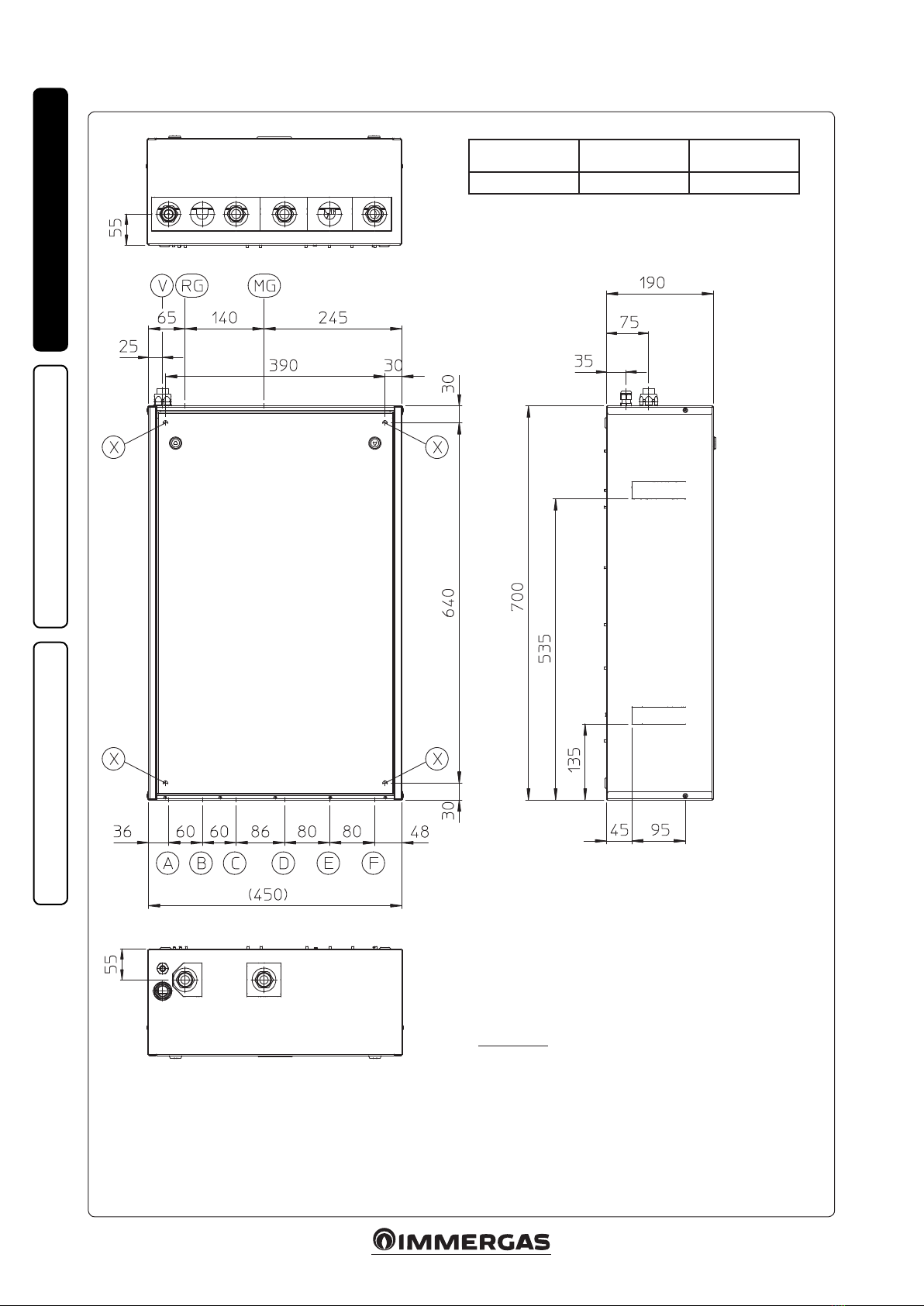
e hydraulic connections must be made in a
rational manner using the values as per Fig. 1-2.
IMPORTANT: remove all the protection caps
from the system ow and return pipes before
making the hydraulic connections.
e connections can be made directly using the
female couplings on the distribution manifold
or by inserting system cut-o cocks (optional).
ese cocks are particularly useful for mainte-
nance as they allow you to drain the distribution
manifold separately without having to empty the
entire system.
N.B.: Immergas does not supply the G1” cocks to
be installed in the low temperature zone.
Check that the expansion vessel present in the
boiler, is sucient to allow the increase in vol-
ume of the water and consequently its heating
without causing the safety valve to open.If this
is not the case, an expansion vessel with appro-
priately dimensioned capacity must be installed
on the system.
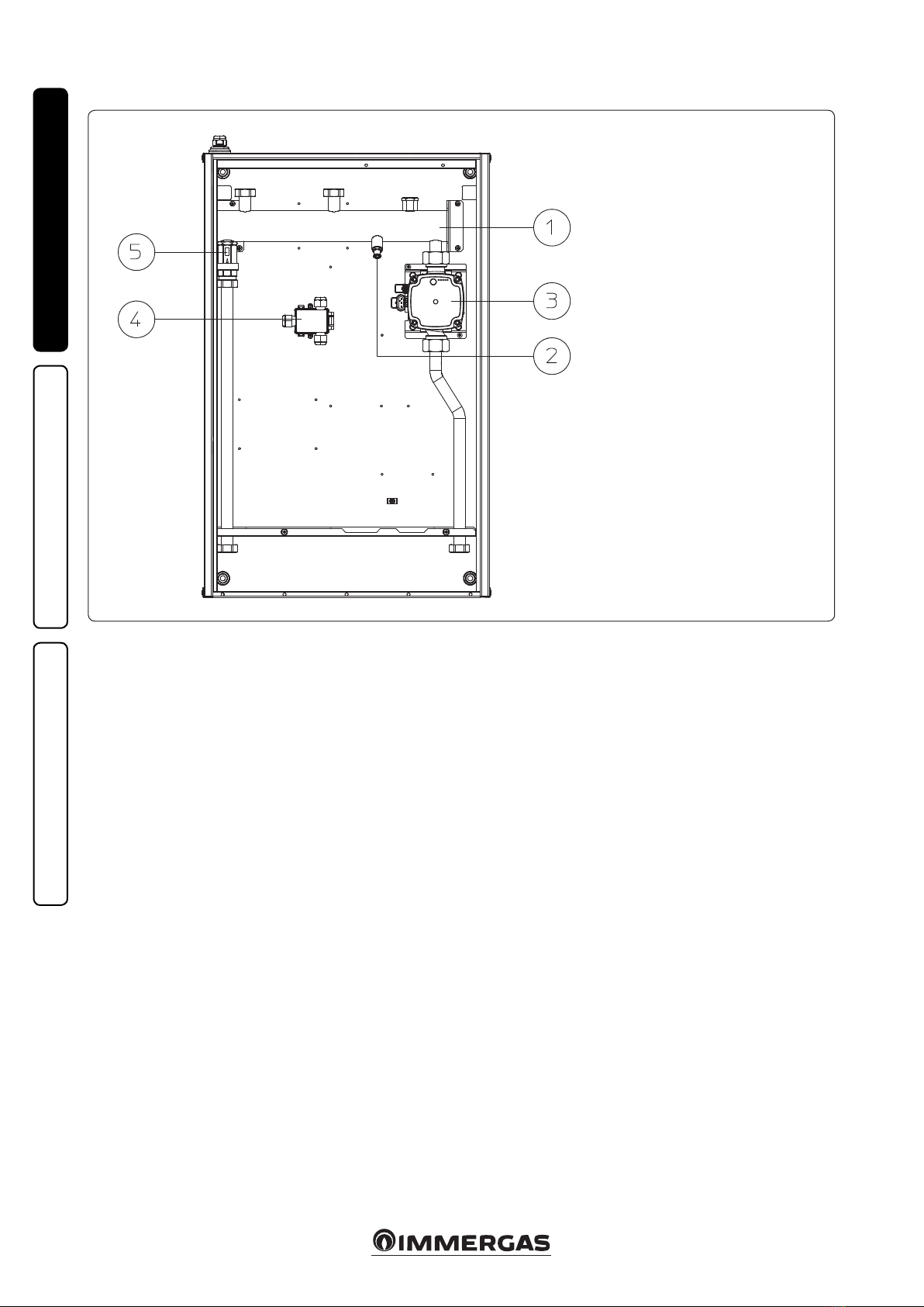
The D.I.M. is set-up for the insertion of the
automatic “jolly” vent valve to be mounted on
the manifold. is is recommended for better
air venting inside the system.
If two D.I.M devices are installed in parallel, two
manual valves must be tted in order to ensure
the correct balance of the hydraulic circuit.
1.5 ELECTRICAL CONNECTION.
e appliance has an IPX5D protection degree,
electrical safety of the appliance is reached only
when it is connected properly to an ecient
earthing system as specied by current safety
standards.
Attention: the manufacturer declines any
responsibility for damage or physical injury
caused by failure to connect the boiler to an
ecient earth system or failure to comply with
the reference standards.
Also ensure that the electrical installation corre-
sponds to maximum absorbed power specica-
tions as shown on the recessed unit data-plate.
e distribution manifold is supplied complete
with an “X” type power cable without plug.
e power supply cable must be connected to a
230V ±10% / 50Hz mains supply respecting L-N
polarity and earth connection; , this network
must also have a multi-pole circuit breaker with
class III over-voltage category.
To protect from possible dispersions of DC
voltage one must provide a type A dierential
safety device.
When replacing the power supply cable, contact
a qualied rm (e.g. the Authorised Aer-Sales
Technical Assistance Service).
For the main power supply to the appliance,
never use adapters, multiple sockets or exten-
sion leads.
Important: it is mandatory to prepare two elec-
trical connection lines in order to separate the
power supply of each distribution manifold from
all other low voltage connections according to the
Standards in force regarding electrical systems.
ese lines must arrive inside the recessed frame
via relevant sheaths or ducts passing through the
fairlead and the sheath-holder supplied, located
on the upper side of the device.
• Connecting the boiler P.C.B. is connection
(low voltage) ensures the dialogue the between
boiler and DIM. Perform the connections as
described in chapter 3.
N.B.: the electrical connection between the
devices must be made using cables with a
minimum section of 0.50 mm2and with a
maximum section of 2.5 mm2; the length of
these connections must not exceed 15 metres.
1.6 ERP DIM BASE INSTALLATION
DIAGRAM.
If a Comando Amico RemotoV2 (C.A.R.V2) or Su-
per C.A.R. zone control remote control or a room
thermostat are used, they must be connected
electrically directly to the boiler (see instructions
in boiler manual).
Attention: it is also necessary to install the relay
board in the boiler as shown in Fig 3-1, cong-
uring relay K2 in “central heating phase active”.
Key:
S20-1 - Room thermostat
1 - External probe (optional)
2 - Boiler
3 - Comando Amico RemotoV2
or Super C.A.R. (optional)
4 - System ow
5 - System return

8
1-4
1-6
1-5
INSTALLERUSER
MAINTENANCE TECHNICIAN
1.7 CIRCULATION PUMP.
e boiler is supplied with circulator tted with
speed regulator.
ese settings are suitable for most systems.
In fact, the pump is equipped with electronic
control to set advanced functions. For proper op-
eration one must select the most suitable type of
operation for the system and select a speed in the
available range, with a focus on energy savings.
Display of operation status. During normal
operation the status LED (2) turns green when
it is in stand-by, the four yellow LEDs (3) in-
dicate circulator absorption according to the
following table:
Circulating pump LED Absorption
G Y Y Y Y
On On O O O
0 ÷ 25 %
G Y Y Y Y
On On On O O
25 ÷ 50 %
G Y Y Y Y
On On On On O
50 ÷ 75 %
G Y Y Y Y
On On On On On
75 ÷ 100 %
Selection of operating mode. To see the current
operation mode it is sucient to press button
(1) once.
To change operation mode press the button for
between 2 to 10 seconds until the current cong-
uration ashing, each time the button is pressed
all possible functions are scrolled cyclically. Aer
a few seconds without doing any operation the
circulator memorises the selected mode and goes
back to operation display.
Attention: e circulator incorporates various
operating modes, however you must choose
between the operating modes listed below (see
g. 1-5 for the representation of the LEDs on
the circulator):
• Proportional pressure. is allows the pres-
sure level (head) to be proportionally reduced
as the system heat demand decreases (ow rate
reduction). anks to this function, the electric
power consumption of the circulator pump is
reduced further: the energy (power) used by
the pump decreases according to the pressure
level and ow rate. With this setting, the pump
guarantees optimal performance in most heat-
ing systems, thereby being particularly suitable
in single-pipe and two-pipe installations. Any
noise of the water ow in the pipes, valves and
radiators is eliminated by reducing the head.
Optimal conditions for thermal comfort and
acoustic well-being.
• Constant pressure. The circulator pump
maintains the pressure level (head) constant
as the system heat demand decreases (ow rate
reduction). With these settings, the circulator
pump is suitable for all oor systems where all
the circuits must be balanced for the same drop
in head.
• Constant curve. e circulator operates main-
taining constant speed.
Selection button lock. e button has a feature
that locks its operation to prevent accidental
modications, to lock the control panel it is
necessary to press button (1) longer than 10
seconds (during which the current conguration
ashes), the active lock is signalled by all LEDs of
the control panel ashing. To unlock the button
press again longer than 10 seconds.
Real time diagnostics: in the event of mal-
function the LEDs provide information on the
circulator operation status, see table (Fig. 1-6).
Circulating pump LED
(rst red LED) Description Diagnostics Remedy
R Y Y Y Y
On O O O On
Circulator pump blocked
The circulator pump cannot
restart automatically due to an
anomaly
Wait for the circulator to make automatic release
attempts or manually release the motor sha acting
on the screw in the centre of the head.
If the anomaly persists replace the circulator.
R Y Y Y Y
On O O On O
Abnormal situation (the circula-
tor continues operating).
low power supply voltage
Voltage o range Check power supply.
R Y Y Y Y
On O On O O
Electrical fault
(Circulator pump blocked)
e circulator is locked due to
power supply too low or serious
malfunction
Check the power supply, if the anomaly persists replace
the circulator.
Key:
1 - Function selection button
2 - Green (G) / red (R) LED
3 - 4 yellow LEDs (Y)
Circulating pump LED Description
G Y Y Y Y
On On O O O
Do not use
G Y Y Y Y
On On O On O
Speed 2 propor-
tional pressure
curve
G Y Y Y Y
On On O On On
Speed 3 propor-
tional pressure
curve
Proportional pressure Constant pressure Constant curve
Circulating pump LED Description
G Y Y Y Y
On O On O O
Do not use
G Y Y Y Y
On O On On O
Speed 3 constant
pressure curve
G Y Y Y Y
On O On On On
Speed 3 constant
pressure curve
Circulating pump LED Description
G Y Y Y Y
On On On O O
Do not use
G Y Y Y Y
On On On On O
Constant curve
speed 2
G Y Y Y Y
On On On On On
Constant curve
speed 3 (default)
G Y Y Y Y
On On On O On
Constant curve
speed 4

9
1-7
V3
V3
V3
V2
V2
V2
A3
A3
V4
A2
A2
A4
A3
A2
INSTALLERUSER
MAINTENANCE TECHNICIAN
Head available to the system.
Key:
Vn = Available head
An = Circulating pump absorbed power
Circulator pump absorbed power (W)Circulator pump absorbed power (W)Circulator pump absorbed power (W)
Flow rate (l/h)
Flow rate (l/h)
Flow rate (l/h)
Head (kPa)Head (kPa)Head (kPa)
Proportional pressure curve.
Constant pressure curve
Constant curve

10
1-8
INSTALLERUSER
MAINTENANCE TECHNICIAN
1.8 MAIN COMPONENTS.
Key:
1 - Hydraulic manifold
2 - Drain tting
3 - Pump
4 - Electrical connection box
5 - “Europa” one-way valve
1.9 SIZING THE SYSTEMS.
e ow temperatures to the various system
zones may be reduced compared to the boiler
outlet temperatures, according to the mixture
of the ow and return uids inside the DIM.
In the event that the DIM is used to feed Low
Temperature zones, check that the design param-
eters allow you to achieve a maximum surface
temperature of the radiant oor in compliance
with standard UNI EN 1264.
1.10 COMMISSIONING THE DEVICE.
System lling. Once the device is connected, ll
the system via the boiler lling valve.
Filling is performed at low speed to ensure release
of air bubbles in the water via the boiler and cen-
tral heating system vents and of the distribution
manifold (if any).
Close radiator vent valves when only water
escapes from them.
Close the lling cock when the boiler pressure
gauge indicates approx. 1.2 bar.
IMPORTANT: during these operations, start
the circulation pumps by acting on the main
switch positioned on the boiler control panel
aer having activated the T.A. devices relating
to the various zones.
1.11 KITS AVAILABLE ON REQUEST.
• System cut-off cock kit (on request). The
manifold is designed for installation of system
interception cocks to be placed on ow and
return pipes of the connection assembly. is
kit is particularly useful for maintenance as it
allows the DIM to be drained separately with-
out having to empty the entire system.
e above-mentioned kits are supplied complete
with instructions for assembly and use.

11
INSTALLERUSER
MAINTENANCE TECHNICIAN
2USE AND MAINTENANCE
INSTRUCTIONS
2.1 GENERAL WARNINGS.
If the device must be deactivated temporarily, act
directly on the main switch to remove voltage
from the system and work safely
• Attention: using any components that use
electrical power requires some fundamental
rules to be observed:
- do not touch the device with wet or moist parts
of the body; do not touch when barefoot.
- if the device is wall-mounted: do not pull the
electric cables, do not leave the device exposed
to the elements (rain, sun, etc.);
- the device power cable must not be replaced by
the user;
- in the event of damage to the cable, switch the
device o and contact exclusively professionally
qualied sta for replacement;
- if the device is not going to be used for a certain
period, disconnect the main power switch.
2.2 WARNINGS FOR THE USER.
is device does not require any regulation or
control by the user. It is therefore prohibited to
open the device front lid.
e only operation that the user must perform
is to periodically check the water pressure of the
system in the boiler. e boiler pressure gauge
should read a value between 1 and 1.2 bar.
If the pressure is below 1 bar (with the circuit cool)
restore normal pressure via the lling valve located
in the boiler (see boiler instruction book).
N.B.: close the valve aer the operation.
If pressure values reach around 3 bar, the boiler
safety valve may be activated.
In this case, remove water from an air vent valve
of a radiator until reaching pressure of 1 bar, or
ask for assistance from professionally qualied
personnel.
In the event of frequent pressure drops, contact
qualied sta for assistance to eliminate any
system leakage.
At the end of its service life the appliance must
not be disposed of like normal household waste
nor abandoned in the environment, but must
be removed by a professionally authorised
company. Contact the manufacturer for disposal
instructions.
2.3 CLEANING THE CASE.
Use damp cloths and neutral detergent to clean
the manifold casing. Never use abrasive or pow-
der detergents.

12
3-1
DIM BASE ERP
CALDAIA
INSTALLERUSER
MAINTENANCE TECHNICIAN
3CHECKS AND
MAINTENANCE
- Check connection to a 230V-50Hz power
mains via an omni-polar disconnector (magne-
tothermal circuit breaker), correct L-N polarity
and the earthing connection;
- check that the magnetothermal circuit breaker
is working properly;
- make sure the central heating system is lled
with water and that the pressure gauge indicates
a pressure of 1-1.2 bar.
- make sure that the air valve cap (if present) is
open and that the system is well deaerated;
- check the activation of the main switch located
upstream of the appliance;
- check sealing eciency of water circuits;
- check the correlation between the electric and
hydraulic connections;
If even only a single safety check oers a negative
result, do not commission the system.
3.1 WIRING DIAGRAM BOILER CONNECTION USING ERP DIM BASE 3RELAY BOARD.
If a remote control or zone control room thermo-
stat is used, its electric connection must be made
directly to the boiler, as described in the relative
instruction book.
Key:
M10-1 - DIM zone 1 pump
K1 - 3-relay board congurable relay (optional)
K2 - 3-relay board congurable relay (optional)
K3 - 3-relay board congurable relay (optional)
If relay K2 is used as active CH phase, the Pin 57 and 58 of connector X 25
positioned on the relay board, must be jumped.
ERP DIM BASE
Black
Blue
Black
Brown.
Brown
Blue
Brown
Blue
BOILER
RELAY BOARD
INTEGRATED BOARD

13
CAR V2
DIM
BASE ERP
CALDAIA
3-2
INSTALLERUSER
MAINTENANCE TECHNICIAN
3.2 WIRING DIAGRAM BOILER CONNECTION USING ERP DIM BASE 1RELAY BOARD.
Only use for boilers equipped with the Coman-
do Amico Remoto V2 remote control and the
internal 1 relay board. In this case the electrical
connection of the CARV2 must be made directly
to the boiler as described in the relative instruc-
tion book.
Key:
M10-1 - DIM zone 1 pump
CARV2 - Comando Amico RemotoV2
ERP DIM BASE
BOILER
Black
Black
Blue
Brown
Brown
Integrated boiler
board
One-relay
board
Boiler electrical
connections area
Blue

14
3-3
DIM BASE ERP
INSTALLERUSER
MAINTENANCE TECHNICIAN
3.3 WIRING DIAGRAM BOILER CONNECTION USING ERP DIM BASE EXTERNAL RELAY.
If a remote control or zone control room thermo-
stat is used, its electric connection must be made
directly to the boiler, as described in the relative
instruction book.
Key:
M10-1 - DIM zone 1 pump
K1 - External relay (optional)
S1 - External relay contact (optional)
S20 - Room thermostat (optional)
ERP DIM BASE
Black
Blue
Blue
Black
Brown
Boiler start
request
Brown
Brown
Blue

15
3-4
INSTALLERUSER
MAINTENANCE TECHNICIAN
3.4 WIRING DIAGRAM DIM BASE ERP CONNECTION TO MULTIZONE P.C.B. KIT.
Key:
M10-1 - DIM zone 1 pump
CARV2 - Comando Amico RemotoV2
Electrical connection
230Vac~50Hz
ERP DIM BASE
Black
Black
Blue
Brown
N
L
Multi-remote P.C.B.
Boiler
low-voltage
terminals
connection
Not used

16
INSTALLERUSER
MAINTENANCE TECHNICIAN
3.5 TROUBLESHOOTING.
- Presence of air in the system. Check the open-
ing of the boiler vents, of the the central heating
system and of the DIM. Make sure the system
pressure and expansion vessel factory-set
pressure values are within the set limits; the
factory-set value for the expansion vessel must
be 1.0 bar, and system pressure between 1 and
1.2 bar.
3.6 TECHNICAL DATA.
ErP DIM Base
Maximum nominal pressure bar 3
Maximum operating pressure °C 90
Water content in device l 0.9
Total head available in direct zone with 1000 l/h ow rate (max) kPa (m c.a.) 42.90 (4.37)
Empty device weight kg 12.5
Full device weight kg 13.9
Electrical connection V/Hz 230/50
Maximum input A 0.60
Installed electric power W 60
Power in Stand-by W 0
Value EEI - ≤ 0.20 - Part. 3
Electric plant protection - IPX5D
Maximum distance between boiler - DIM m 15

1717

1818

1919

Follow us
Immergas Italia
immergas.com
Immergas S.p.A.
42041 Brescello (RE) - Italy
Tel. 0522.689011
Fax 0522.680617
Certied company ISO 9001
is instruction booklet is made of ecological paper Cod. 1.039169ENG - rev. ST.002144/001 - 02/18 - Inglese per IRLANDA (IE)
Other manuals for ERP DIM BASE
1
Other Immergas Digital Manifold manuals