manuals.online logo
Brands
  1. Home
  2. •
  3. Brands
  4. •
  5. CALEFFI
  6. •
  7. Plumbing Product
  8. •
  9. CALEFFI LEGIOMIX 6000AS Series User manual

CALEFFI LEGIOMIX 6000AS Series User manual

OVERVIEW - READ BEFORE PROCEEDING!
1. Refer to the LEGIOMIX Quick Start Guide and instruction sheet, code H0002997, for complete instructions on setup
and commissioning.
2. Do not mount station in orientation with actuator upside down. If mounted other than shown, and not with actuator
upside down, remount the controller to normal horizontal position as it is shown here.
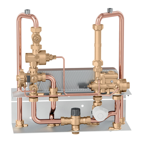
2. The LEGIOMIX Station components are shown below:
LEGIOMIX®Station electronic mixing system
6000AS series
© Copyright 2021 Caleffi
NA10679.02
www.caleffi.com
1
INSTALLATION GUIDE
Mix Out Recirc
Return
Purge to
prime the
recirculation
pump
To Tank
11
1
2
2
Keyed components:
1. Serviceable dual union check valves (4).
2. Isolation ball valves (5).
3. 24 V wall plug-in transformer with 20 ft cable
(not shown in this view). Strapped to strut for shipment.
4. LEGIOMIX valve/actuator.
5. Connect recirculation pump (not included, source separately) to this line.
Purge to test/
commission
Strut frame
Hot In Cold In
Extra DIN rail for
accessories
3
4
22
2
1
5
Provide with optional Modbus-to-BACnet gateway for BAS integration,
code NA10520.
Technical specifications
Mixing valve body
Materials: - Body: DZR low-lead brass
- Ball: low-lead brass, chrome-plated
- Hydraulic seals: peroxide-cured EPDM
Max. body pressure rating (static): 230 psi (16 bar)
Max. operating pressure: 150 psi (10 bar)
Max. inlet temperature: 212°F (100°C)
Temperature gauge scale: 30 - 210°F
Suitable fluids: water
Max. water hardness: 10 grains
Actuator, 3-wire floating
Electric supply: 24 VAC - 50/60 Hz
Power consumption: 6 VA
Protection cover: self-extinguishing VO
Protection class: IP 65 (NEMA 4/4X)
Ambient temperature range: 14 - 130°F (-10 - 55°C)
Electric supply cable length: 31½” (0.8 m)
Max. distance for control signal wire:
500 ft (150 m) cable 2 conductor x AWG 18
800 ft (250 m) cable 2 conductor x AWG 16
Station components
Frame: steel uni-strut
Pipes: copper type L
Ball valves: low-lead brass
Check valves: stainless steel
Main connections: -copper
1”, 1¼”, 1½”, 2” & 2½”
Controller, LCD user interface/display
Materials: - Housing: self-extinguishing ABS, color white RAL 1467
- Cover: self-extinguising SAN, smoked transparent
Electric supply: 24 VAC (min 21.6, max 26.0 VAC) - 50/60 Hz
Power consumption: 6.5 VA
Adjustment temperature range: 70 - 185°F (20 - 85°C)
Disinfection temperature range: 100 - 185°F (40 - 85°C)
Ambient temperature range: 32 - 120°F (0 - 50°C)
Protection class: IP 54 (wall mounting)
(Class II appliance)
Mounting bracket: DINrail
Mixing valve actuator current draw: 1 A max / 24 V
Alarm relay (R2): 5 A resistance (2 A inductance) / 24 V
Contact rating (R1, R3, R4): 10 A resistance (2 A inductance) / 24 V
(A 50 VA Class 2 120/24 VAC transformer is included)
Fuses: 1 (main): 80 mA
Fuses: 2 (mixing valve): 1 A
Charge reserve: 15 days in the event of electric supply failure,
with a 3 cell rechargeable 3.6 V 140 mAh buffer battery
Battery recharging time: 72 hours
Approvals: CE, FCC part 15
Temperature sensors
Body material: stainless steel
Type of sensitive element: NTC
Working temperature range: 14 - 260°F (-10 - 125°C)
Resistance: 1000 Ohms at 77° F (25° C)
Time constant: 2.5
Max. distance for mixed outlet or return (recirculation) sensor:
500 ft (150 m) cable 2 conductor x AWG 18
800 ft (250 m) cable 2 conductor x AWG 16
Mixing valve performance
Accuracy: ± 3º F (± 2º C)
Max. operating differential pressure (dynamic): 75 psi (5 bar)
Max. ratio between inlet pressures (H/C or C/H): 2.1
Certifications
1. ASSE 1017/CSA B125.3, certified by ICC-ES, file PMG-1357.
2. The valve body component meets the requirement of CSA Z317.1
Special Requirement for Plumbing Installations in Health Care
Facilities, certifed by ICC-ES, file PMG-1357.
3. The valve body complies with NSF/ANSI 372, Drinking Water System
Components-Lead Content Reduction of Lead in Drinking Water Act,
California Health and Safety Code 116875 S.3874, Reduction in
Drinking Water Act, Vermont Act 193 - The Lead in Plumbing
Supplies Law and Maryland’s Lead Free Law HB.372, as certified by
ICC-ES, file PMG-1360.
Station assembly
Includes pre-piped LEGIOMIX 3-way mixing valve with union connections,
serviceable low-lead stainless steel check valves, a recirculation connection
and isolation valves for fast and simple installation. The LEGIOMIX controller is
pre-mounted and pre-wired and includes a return water temperature sensor,
in a packaged wall mount configuration with steel uni-strut frame that can bolt
to the wall through any of the perforations. The assembly also includes copper
type L pipe, low lead ball valves and a plug-in 24 VAC transformer with 10
feet of wire.
2
LEGIOMIX Station sizing and selection procedure
3
A. Obtain the maximum GPM (demand) of domestic hot water from project documentation.
B. Select station size which has a Max GPM value equal to or greater than the project maximum GPM demand.
(1) The maximum GPM rating for the LEGIOMIX station is based on 5 feet per second pipe velocity in the station's
copper tubing. This velocity recommendation is for water temperatures up to 140°F and is from the UPC (Uniform
Plumbing Code) and the CDA (Copper Development Assocation) "Copper Tube Handbook". To minimize the
potential of erosion-corrosion in the station piping, do not exceed 5 fps velocity.
(2) The PSI/GPM table is for reference only, showing various GPM values at various pressure drops across the
station.
Pressure drop across station (PSID)
1 1.5 2 3 5 7.5
Station size 2Flow rates (GPM) @ above pressure drop
1" 7.8 9.5 11.0 13 17 21
1¼" 9.0 11 13 16 20 25
1½" 20 24 28 34 44 54
2" 38 47 54 66 85 105
2½" 43 52 60 74 96 117
Station Code Station Size
1Max. GPM
(@ 5 fps pipe
velocity) Station Cv
600066AS 1" 14 7.8
600076AS 1¼" 20 9
600086AS 1½" 29 20
600096AS 2" 50 38
600060AS 2½" 76 43
Caleffi North America, Inc.
3883 West Milwaukee Road
Milwaukee, WI 53208
T: 414.238.2360 F: 414.238.2366
8-23-2021
LEAVE THIS GUIDE WITH USER
4
Dimensions
1
1
2
2
3
3
4
4
A A
B B
SCALE
TOLERANCES UNLESS NOTED
SHEET
DIMENSIONING AND TOLERANCING PER ASME Y14.5M-1994
PROJECT:
DWN
CHKD
DATE
DATE
THIRD ANGLE
NOTICE ON REPRODUCTIONS
ANGLESDECIMALS
FINISH
MATERIAL
TITLE
PN
SIZE
Legiomix Station 1"
THIS DRAWING, THE DE SIGN AND THE PATE NTS IT COVERS, A RE THE PROPERTY OF
CALEFFI INC. THEY ARE LOANED MERELY A ND ON THE BORROW ER'S EXPRESS AGRE EMENT
THAT THEY W ILL NOT BE REPROD UCED, COPIED, LO ANED, EXHIBITED , NOR USED EXCEP T
IN THE LIMITED WAY A ND THE PRIVATE US E PERMITTED BY WR ITTEN CONSENT GIV EN BY
THE LENDER TO THE BORROWE R.
10/29/2018
PATH:
C:\InventorWork\Workspace\Mix Valves\LegioMix station\LegioMixStation 1 inch.iam
Mike
2
REV
.X ±
.XX ±
.XXX ±
X° ±
B
CALEFFI NORTH AMERICA
3883 West Milwaukee Road
Milwaukee, WI 53208
A
B C
D
E
F
H
I
G
LegioMix Station Assembly Dimensions
LegioMix As
mDESCRIPTION A B C D E F G H I
600066AS
1" 24.75 7.5 8.25 5.25 35.25 32 39 3.5 3.5
600076AS
1.25" 27 7.5 9 6.25 39.25 36 43 3.5 3.5
600086AS
1.5
600096AS
2"
Code connections A B C D E F G H/I Wt
(lb)
600066AS 1" copper 24 ¾" 7 ½" 8 ¼" 5 ¼" 35 ¼" 32" 39" 3½" 130
600076AS 1¼" copper 27" 7 ½" 9" 6 ¼" 39 ¼" 36" 43" 3½" 148
600086AS 1½" copper 35 3/8" 8 ½" 13 ¼" 5 5/8" 47 ½" 50" 58" 4" 219
600096AS 2" copper 36 ¾" 8 7/8" 14 ¼" 5 3/8" 47 ¼" 50" 60" 5" 248
600060AS 2½" copper 43 1/8" 8 7/8" 14 ¼" 6 3/16" 54 3/8" 60" 70" 5" 250
WARNING: This product can expose you to chemicals including lead, which is
known to the State of California to cause cancer and birth defects or other
reproductive harm. For more information go to www.P65Warnings.ca.gov.
AVERTISSEMENT:
Ce produit peut vous exposer à des produits chimiques comme
le plomb, qui est connu dans l’État de Californie pour causer le cancer, dommages à
la naissance ou autre. Pour plus d’informations rendez-vous www.P65Warnings
ca.gov.

This manual suits for next models

5

Other CALEFFI Plumbing Product manuals

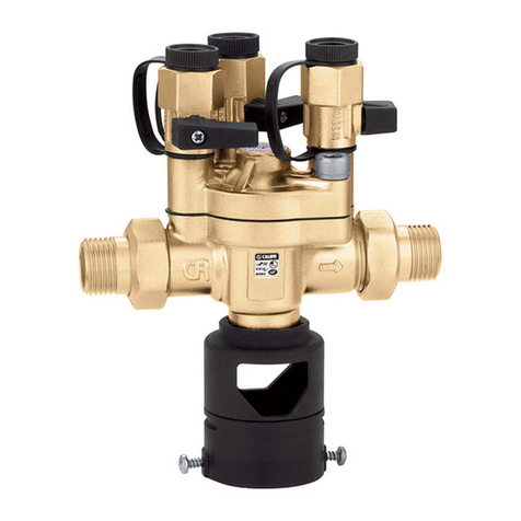
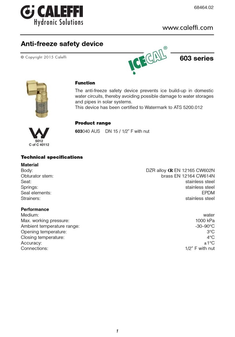
CALEFFI 603 Series User manual

CALEFFI

CALEFFI 603 Series User manual

CALEFFI SATK15313 ABC User manual

CALEFFI

CALEFFI SATK15313 ABC User manual

CALEFFI 574 series User manual

CALEFFI

CALEFFI 574 series User manual

CALEFFI 359902 User manual

CALEFFI

CALEFFI 359902 User manual

CALEFFI 574011 User manual

CALEFFI

CALEFFI 574011 User manual

CALEFFI 319 Series User manual

CALEFFI

CALEFFI 319 Series User manual

CALEFFI 255 Series User manual

CALEFFI

CALEFFI 255 Series User manual

CALEFFI SATK16315 Guide

CALEFFI

CALEFFI SATK16315 Guide

CALEFFI 579 Series Guide

CALEFFI

CALEFFI 579 Series Guide

CALEFFI 664 Series User manual

CALEFFI

CALEFFI 664 Series User manual

CALEFFI 5022 Series User manual

CALEFFI

CALEFFI 5022 Series User manual

CALEFFI 5200 Series User manual

CALEFFI

CALEFFI 5200 Series User manual

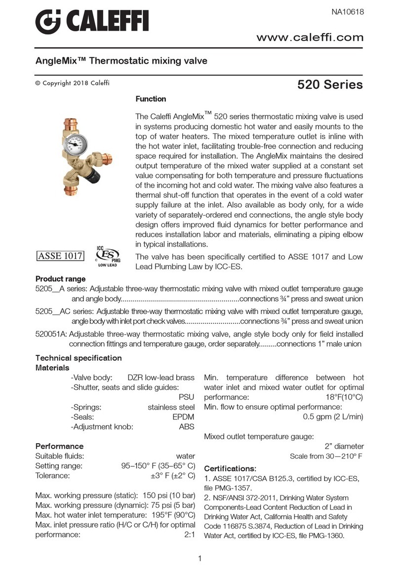
CALEFFI AngleMix 520 Series User manual

CALEFFI

CALEFFI AngleMix 520 Series User manual

CALEFFI 639042 Guide

CALEFFI

CALEFFI 639042 Guide

CALEFFI 508013A User manual

CALEFFI

CALEFFI 508013A User manual

Popular Plumbing Product manuals by other brands

Hewi 815.06.110 Series Mounting instructions

Hewi

Hewi 815.06.110 Series Mounting instructions

Sentiotec WELLFUN CORNER Assembly instruction

Sentiotec

Sentiotec WELLFUN CORNER Assembly instruction

Kohler 8881T-VC01-BN installation instructions

Kohler

Kohler 8881T-VC01-BN installation instructions

Grohe Essence 19 494 manual

Grohe

Grohe Essence 19 494 manual

Hans Grohe AXOR One Select 48112 9 Series Installation

Hans Grohe

Hans Grohe AXOR One Select 48112 9 Series Installation

EQUATION 3276000700180 instruction manual

EQUATION

EQUATION 3276000700180 instruction manual

Kohler 10282 installation instructions

Kohler

Kohler 10282 installation instructions

Moen 84576 Series manual

Moen

Moen 84576 Series manual

Glacier bay 67732W-6001 Installation and care guide

Glacier bay

Glacier bay 67732W-6001 Installation and care guide

KWC FAMOSO K.12.W1.42 Installation and service instructions

KWC

KWC FAMOSO K.12.W1.42 Installation and service instructions

Moen TFS5001BN installation guide

Moen

Moen TFS5001BN installation guide

ZUHNE MODENA 23 use and care manual

ZUHNE

ZUHNE MODENA 23 use and care manual

Aqualisa OPTIC Q user guide

Aqualisa

Aqualisa OPTIC Q user guide

ADCA AE30 Installation and maintenance instructions

ADCA

ADCA AE30 Installation and maintenance instructions

Artos F703-9 installation guide

Artos

Artos F703-9 installation guide

Grohe Tectron 37749 manual

Grohe

Grohe Tectron 37749 manual

BELLOSTA funtanin joy 8003 installation instructions

BELLOSTA

BELLOSTA funtanin joy 8003 installation instructions

glass 1989 Chillout Series manual

glass 1989

glass 1989 Chillout Series manual

manuals.online logo
manuals.online logoBrands
  • About & Mission
  • Contact us
  • Privacy Policy
  • Terms and Conditions

Copyright 2025 Manuals.Online. All Rights Reserved.