California Accent Lighting lipLEDs LLED8600-RME User manual

CALIFORNIA ACCENT LIGHTING, INC.
2034 E. Lincoln Ave. #431, Anaheim, CA 92806
ph. 800.921.CALI (2254) or 714.535-7900 \ fx. 714.535.7902
© CALI. All rights reserved. CALI reserves the right to make changes or withdraw specications without prior notice.
Installation Instructions Overview
lipLEDs™LLED8600-RME
1 of 21
End View
Extrusion
(#LLED8600-RME)
1.38”
.75”
.60”.70”
1.80”
Power Connector
(#LLED8600-PC)
RGBW StripLite
(#LLED8600)
Frosted Lens Cover
(#LLED8600-RME-LF)
IMPORTANT VERIFY CORRECT
LUMINAIRE WAS RECEIVED WITH
CORRECT COLOR TEMPERATURE
AND VOLTAGE BEFORE CUTTING
OR INSTALLING. CALI WILL NOT
BE RESPONSIBLE IF INCORRECT
LUMINAIRE IS INSTALLED.
• Electric compound miter saw
• 14.4 to 28 volt cordless drill
• Drill bits - concrete or wood
• Electrical cords
• Safety glasses
• Marker
• Electric hammer drill (optional)
• Phillips bits - sufficient quantity
• Electrical three ways
• Measuring tape
• Chalk line
• Sharp scissors
• Soldering iron with kit
PRODUCT INFORMATION
• For accent, cove, edge, under cabinet lighting
• 24 volts DC for easy and safe installation
• Long life, energy efficient LEDs
• Maximum run based on 5 Amps: 21’ (5.5W), 26’ (4.5W)
For class II applications: 17’ (5.5W), 21’ (4.5W)
• Can be ordered to specific lengths for easier installation when exact
dimensions are known (Example: 10x10’6”)
• Plug and light system
• Lead wires are typically 33” long and exit on one end
ELECTRICAL
• LipLEDs products require a 24 volt DC remote transFORMER
• To calculate transformers size find watts per foot
(Example: 4.5W per foot)
• Determine length in feet (Example: 10’)
• Calculate Load: Multiply Watts per Foot x Length in Feet
(Example: 4.5W x 10’= 45W)
• Choose an electronic transFORMER from catalog (Example: TRA60-E)
• Determine maximum distance using Maximum Wire Length Table
(Example: 45 watts is between 40W and 80W. Using #14 wire,
maximum distance is 37’ from transFORMER to first LED)
INSTALLATION TOOLS REQUIRED
INSTALLATION RECOMMENDATIONS
• LipLEDs LED tape must be mechanically attached
directly to mounting surface using mounting clips or channels
• Conduit raceway should be sleeved at one end for low voltage wires
going to transFORMER
2” increments up to max run
± 0.125” cutting tolerance
*See max run for more information
2”
6” increments up to max run
*See max run for more information
6”
2” increments up to max run
± 0.125” cutting tolerance
*See max run for more information
(Run lengths required)
2”
3.9” or 6.5”
6.5”
2” increments up to max run
± 0.125” cutting tolerance
*See max run for more information
2”
8’ Maximum extrusion and lens length
(Dry Location field cuttable)
Lens and extrusion shipped in
8’ sections (field cuttable)
8’ Maximum extrusion and lens length
3.95” increments up to max run
± 0.125” cutting tolerance
*See max run for more information
3.95”
LLED8400 --->
LLED8000 --->
LLED8200 --->
LLED8300 --->
LLED8500 --->
LLED8100 --->
Specify Length (19.7”Assembly Increments)
(Add 2.5” to run for end cap and strain relief)
.75”
5.5W
.78”
.52”
*1.5W, 2.5W,
3.6W, 4.5W
.47”
.36”
6.5” (2.5W) or 3.9” (5.5W) increments up to max run
± 0.125” cutting tolerance
*See max run for more information
6.5“ increments up to max run
± 0.125” cutting tolerance
*See max run for more information
3.9” 3.9” increments up to max run
± 0.125” cutting tolerance
*See max run for more information
3.9” 3.9” increments up to max run
± 0.125” cutting tolerance
*See max run for more information
3.9” 3.9” increments up to max run
± 0.125” cutting tolerance
*See max run for more information

CALIFORNIA ACCENT LIGHTING, INC.
2034 E. Lincoln Ave. #431, Anaheim, CA 92806
ph. 800.921.CALI (2254) or 714.535-7900 \ fx. 714.535.7902
© CALI. All rights reserved. CALI reserves the right to make changes or withdraw specications without prior notice.
Installation Instructions Overview
lipLEDs™LLED8600-RME
2 of 21
WARNING
When using lipLEDs for any application, basic safety precautions
should always be followed to reduce the risk of fire, electric shock,
and personal injury. lipLEDs must be installed in accordance with
the NEC or CEC as applicable.
• Do not exceed maximum length per circuit. Each maximum run requires
additional power feed from the transformer
• Do not cover lipLEDs as the covering may cause it to overheat, melt, or ignite.
• Do not install lipLEDs in hazardous locations or closer than 6 inches
from any curtain or similar combustible material.
• Do not use lipLEDs if damaged, such as broken outer jacket, loose
connections, or frayed wire insulation. Inspect periodically.
• Do not submerge lipLEDs in liquid.
• Do not mount lipLEDs with staples, nails, or like means that might
damage the insulation. Mount with double-sided tape and mounting clips.
• Do not install lipLEDs in places where it is subject to continuous flexing.
• Do not mount lipLEDs inside tanks or enclosures of any kind without
sufficient ventilation.
• Ground Fault Circuit Interrupter (GFCI) protections are required
on circuits or outlets.
• Surge protector must be set up for electrical power system to avoid
damaging lipLEDs lighting system.
• Do not install in an environment where excessive heat may exist.
Ambient temperature -40°F - 122°F (-20°C - 50°C).
• Only wet location models are intended for outdoors. See package label
for environmental details.
• Do not install wet location model in areas where water will collect.
• Do not attempt to wire without wiring diagram. Only wire based on
provided wiring diagrams
*Maximum run is based on 5 Amps: 21’ (5.5W), 26’ (4.5W)
For class II applications: 17’ (5.5W), 21’ (4.5W)
APPLICATIONS Accent, Decorative Lighting
VOLTAGE 24VDC
LAMP TYPE Color Changing RGBW LEDs
DIMMING DMX-512
LENGTH Built to Order
MOUNTING Mounting Channel
VIEWING ANGLE 120 Degrees
L70 LED LIFE 50,000 hrs.
MAXIMUM RUN* 21’ (5.5W)
26’ (4.5W)
LISTING Dry or Wet (IP65 or IP67) Location
UL2108, CSA C22.2#9
UL8750, CSA250
FEATURES
(Based on 5 amps)

CALIFORNIA ACCENT LIGHTING, INC.
2034 E. Lincoln Ave. #431, Anaheim, CA 92806
ph. 800.921.CALI (2254) or 714.535-7900 \ fx. 714.535.7902
© CALI. All rights reserved. CALI reserves the right to make changes or withdraw specications without prior notice.
Installation Instructions
lipLEDs™LLED8600-RME
3 of 21
Product Care
Do not bend lightstrip to a diameter of less than 1.5”
Do not bend lightstrip along a horizontal plane
Do not connect lightstrip to power source while spooled or coiled
Do not overlap lightstrips at any location
Do not install lightstrip in a zig-zag fashion
Do not install mounting clip over LED diode Do not penetrate lightstrip with any foreign object
Do not apply excessive pressure to surface of lightstrip or LEDs
Do not fold, crease, or twist lightstrip
Do not cover lightstrip with any material
Do not install connectors without shrink tube for wet locationDo not use a lighter to heat shrink tube
Do not install wet location in outdoor cove without proper drainage
Do not cross or overlap extrusions and twist lightstrip to overlap
3.9” 3.9”
<1.5”
<1.5”
(<38.1mm)
(<38.1mm)
TRA
6”
4”
<1.5”
<1.5”
.75”
.75”
3.9” 3.9”
<1.5”
<1.5”
(<38.1mm)
(<38.1mm)
TRA
6”
4”
<1.5”
<1.5”
.75”
.75”
3.9” 3.9”
<1.5”
<1.5”
(<38.1mm)
(<38.1mm)
TRA
6”
4”
<1.5”
<1.5”
.75”
.75”
3.9” 3.9”
<1.5”
<1.5”
(<38.1mm)
(<38.1mm)
TRA
6”
4”
<1.5”
<1.5”
.75”
.75”
3.9” 3.9”
<1.5”
<1.5”
(<38.1mm)
(<38.1mm)
TRA
6”
4”
<1.5”
<1.5”
.75”
.75”
3.9” 3.9”
<1.5”
<1.5”
(<38.1mm)
(<38.1mm)
TRA
6”
4”
<1.5”
<1.5”
.75”
.75”
3.9” 3.9”
<1.5”
<1.5”
(<38.1mm)
(<38.1mm)
TRA
6”
4”
<1.5”
<1.5”
.75”
.75”
3.9” 3.9”
<1.5”
<1.5”
(<38.1mm)
(<38.1mm)
TRA
6”
4”
<1.5”
<1.5”
.75”
.75”
3.9” 3.9”
<1.5”
<1.5”
(<38.1mm)
(<38.1mm)
TRA
6”
4”
<1.5”
<1.5”
.75”
.75”
3.9” 3.9”
<1.5”
<1.5”
(<38.1mm)
(<38.1mm)
TRA
6”
4”
<1.5”
<1.5”
.75”
.75”
3.9” 3.9”
<1.5”
<1.5”
(<38.1mm)
(<38.1mm)
TRA
6”
4”
<1.5”
<1.5”
.75”
.75”
3.9” 3.9”
<1.5”
<1.5”
(<38.1mm)
(<38.1mm)
TRA
6”
4”
<1.5”
<1.5”
.75”
.75”
3.9” 3.9”
<1.5”
<1.5”
(<38.1mm)
(<38.1mm)
TRA
6”
4”
<1.5”
<1.5”
.75”
.75”
3.9” 3.9”
<1.5”
<1.5”
(<38.1mm)
(<38.1mm)
TRA
6”
4”
<1.5”
<1.5”
.75”
.75”
3.9” 3.9”
<1.5”
<1.5”
(<38.1mm)
(<38.1mm)
TRA
6”
4”
<1.5”
<1.5”
.75”
.75”

CALIFORNIA ACCENT LIGHTING, INC.
2034 E. Lincoln Ave. #431, Anaheim, CA 92806
ph. 800.921.CALI (2254) or 714.535-7900 \ fx. 714.535.7902
© CALI. All rights reserved. CALI reserves the right to make changes or withdraw specications without prior notice.
Installation Instructions
lipLEDs™LLED8600-RME
4 of 21
Application Guidelines
One person on one end applies pressure
to LLED8600, securing it to channel
LLED8600-RME REQUIRES A TEAM EFFORT TO ENSURE SECURE AND CORRECT INSTALLATION
Another person unreels LLED8600 from
spool, holding lightstrip at 45° angle
45°
Apply pressure to
lightstrip, ensuring
adherence to channel
Feed from wire puller stand
Double stick
tape backing

CALIFORNIA ACCENT LIGHTING, INC.
2034 E. Lincoln Ave. #431, Anaheim, CA 92806
ph. 800.921.CALI (2254) or 714.535-7900 \ fx. 714.535.7902
© CALI. All rights reserved. CALI reserves the right to make changes or withdraw specications without prior notice.
Installation Instructions
lipLEDs™LLED8600-RME
5 of 21
Typical Layouts
DMX-RGBW-128C
(Optional, Included)
Up to max run length
DMX-RGBW-3A
(Required, Included)
Up to max run length
DMX-RGBW-3A
(Required, Included)
DMX-RGBW-128C
(Optional, Included)
Up to max run length
DMX-RGBW-3A
(Required, Included)
DMX-RGBW-128C
(Optional, Included)
Up to max run length
DMX-RGBW-3A
(Required, Included)
Up to max run length
DMX-RGBW-3A
(Required, Included)
Up to max run length
DMX-RGBW-3A
(Required, Included)
TRAXXX-E-UNV-24VDC-10V
(Required, Not Included)
(Must use electronic transformer)
LED Lighting
LED Lighting
LED LightingLED Lighting
TRAXXX-E-UNV-24VDC-10V
(Required, Not Included)
(Must use electronic transformer)
TRAXXX-E-UNV-24VDC-10V
(Required, Not Included)
(Must use electronic transformer)
TRAXXX-E-UNV-24VDC-10V
(Required, Not Included)
(Must use electronic transformer)
TRAXXX-E-UNV-24VDC-10V
(Required, Not Included)
(Must use electronic transformer)
TRAXXX-E-UNV-24VDC-10V
(Required, Not Included)
(Must use electronic transformer)
DMX-RGBW-128C
(Optional, Included)
Up to max run length
DMX-RGBW-3A
(Required, Included)
Up to max run length
DMX-RGBW-3A
(Required, Included)
DMX-RGBW-128C
(Optional, Included)
Up to max run length
DMX-RGBW-3A
(Required, Included)
DMX-RGBW-128C
(Optional, Included)
Up to max run length
DMX-RGBW-3A
(Required, Included)
Up to max run length
DMX-RGBW-3A
(Required, Included)
Up to max run length
DMX-RGBW-3A
(Required, Included)
TRAXXX-E-UNV-24VDC-10V
(Required, Not Included)
(Must use electronic transformer)
LED Lighting
LED Lighting
LED LightingLED Lighting
TRAXXX-E-UNV-24VDC-10V
(Required, Not Included)
(Must use electronic transformer)
TRAXXX-E-UNV-24VDC-10V
(Required, Not Included)
(Must use electronic transformer)
TRAXXX-E-UNV-24VDC-10V
(Required, Not Included)
(Must use electronic transformer)
TRAXXX-E-UNV-24VDC-10V
(Required, Not Included)
(Must use electronic transformer)
TRAXXX-E-UNV-24VDC-10V
(Required, Not Included)
(Must use electronic transformer)
DMX-RGBW-128C
(Optional, Included)
Up to max run length
DMX-RGBW-3A
(Required, Included)
Up to max run length
DMX-RGBW-3A
(Required, Included)
DMX-RGBW-128C
(Optional, Included)
Up to max run length
DMX-RGBW-3A
(Required, Included)
DMX-RGBW-128C
(Optional, Included)
Up to max run length
DMX-RGBW-3A
(Required, Included)
Up to max run length
DMX-RGBW-3A
(Required, Included)
Up to max run length
DMX-RGBW-3A
(Required, Included)
TRAXXX-E-UNV-24VDC-10V
(Required, Not Included)
(Must use electronic transformer)
LED Lighting LED Lighting
LED LightingLED Lighting
TRAXXX-E-UNV-24VDC-10V
(Required, Not Included)
(Must use electronic transformer)
TRAXXX-E-UNV-24VDC-10V
(Required, Not Included)
(Must use electronic transformer)
TRAXXX-E-UNV-24VDC-10V
(Required, Not Included)
(Must use electronic transformer)
TRAXXX-E-UNV-24VDC-10V
(Required, Not Included)
(Must use electronic transformer)
TRAXXX-E-UNV-24VDC-10V
(Required, Not Included)
(Must use electronic transformer)
SINGLE RUN
• Capable of displaying one scene at a time on a single run of RGBW lighting (LLED8600)
• Scene must be set using DMX Controller (DMX-RGBW-128C) or by setting DMX address with
DIP switches on DMX Decoder (DMX-RGBW-3A)
• Uses a single power source
• Optimal for single runs displaying a single scene
SERIES RUN
• Capable of simultaneously displaying multiple scenes across multiple runs of RGBW lighting
(LLED8600)
• Scenes must be set using DMX Controller (DMX-RGBW-128C) or by setting DMX address with
DIP switches on DMX Decoder (DMX-RGBW-3A)
• Uses multiple power sources
• Each run has its own transformer, DMX Decoder, and DMX Controller (optional)
• Optimal for displaying multiple scenes across multiple runs
Configuration A (with DMX Controller)
Configuration C (with DMX Controller)
Configuration B (without DMX Controller)
Configuration D (without DMX Controller)

CALIFORNIA ACCENT LIGHTING, INC.
2034 E. Lincoln Ave. #431, Anaheim, CA 92806
ph. 800.921.CALI (2254) or 714.535-7900 \ fx. 714.535.7902
© CALI. All rights reserved. CALI reserves the right to make changes or withdraw specications without prior notice.
Installation Instructions
lipLEDs™LLED8600-RME
6 of 21
Typical Layouts cont.
TRA60-E-UNV-24VDC-10V
(Not Included)
(Must use electronic transformer)
8’
LLED8600 5.5W
DMX-RGBW-3A
(Required, Included)
DMX-RGBW-3A
(Required, Included)
DMX-RGBW-3A
(Required, Included)
DMX-RGBW-3A
(Required, Included)
DMX-RGBW-3A
(Required, Included)
DMX-RGBW-3A
(Required, Included)
DMX-RGBW-3A
(Required, Included)
DMX-RGBW-3A
(Required, Included)
DMX-RGBW-3A
(Required, Included)
DMX-RGBW-128C
(Optional, Included)
LED Lighting
LED Lighting
LED Lighting
LED Lighting
LED Lighting
LED Lighting
LED Lighting
LED Lighting
Junction Box
(Not Included, by others)
Junction Box
(Not Included, by others)
TRAXXX-E-UNV-24VDC-10V
(Required, Not Included)
(Must use electronic transformer)
TRAXXX-E-UNV-24VDC-10V
(Required, Not Included)
(Must use electronic transformer)
PARALLEL RUN WITH ONE SCENE
• Capable of displaying one scene across multiple runs of RGBW lighting (LLED8600)
• Uses a single power source
• Each fixture can be controlled independently with the controller
• Cumulative length of all fixtures must be within max run length and max load
Configuration E (with DMX Controller)
Configuration D (without DMX Controller)

CALIFORNIA ACCENT LIGHTING, INC.
2034 E. Lincoln Ave. #431, Anaheim, CA 92806
ph. 800.921.CALI (2254) or 714.535-7900 \ fx. 714.535.7902
© CALI. All rights reserved. CALI reserves the right to make changes or withdraw specications without prior notice.
Installation Instructions
lipLEDs™LLED8600-RME
7 of 21
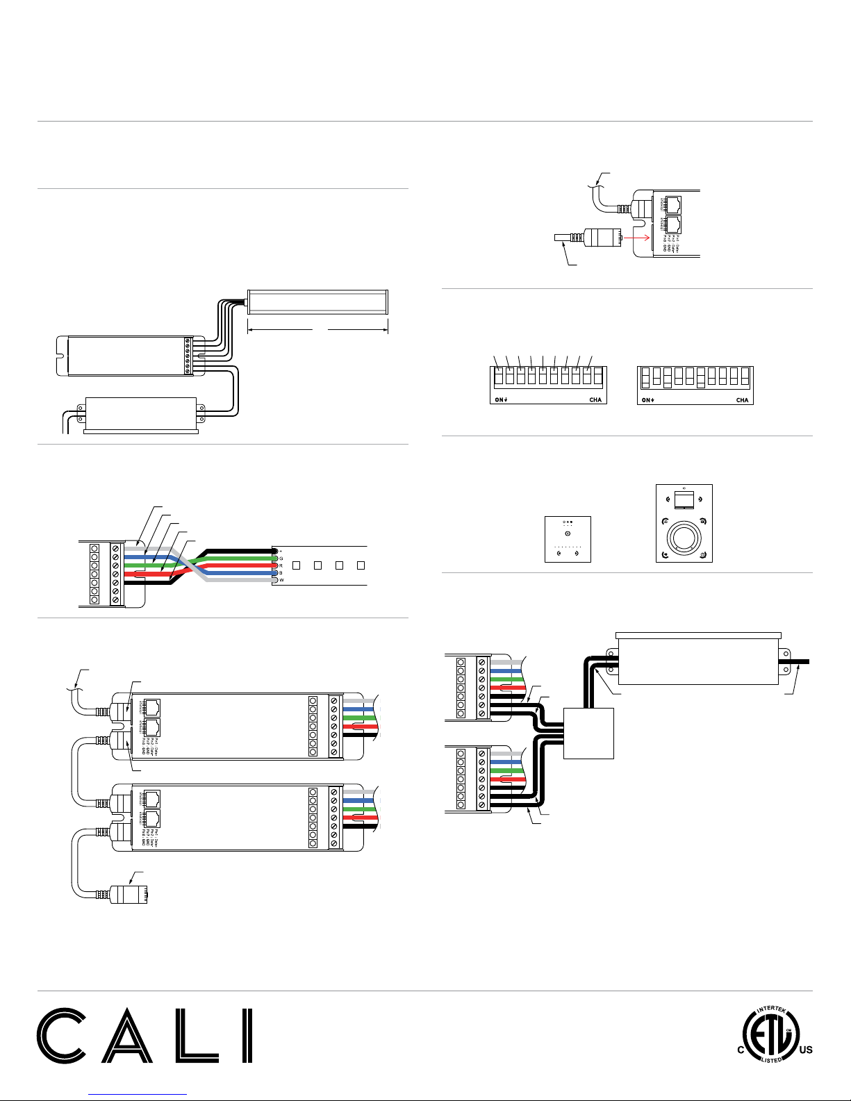
Setup of Decoder with Controller
Setup with DMX Controller (Recommended)
1. Determine which configuration best suits your application.
Refer to typical layouts on pages 5 - 6.
2. Calculate load. Use the below diagram as a reference to the calculations that follow.
Calculate load by multiplying watts per foot by length in feet. Add 1W for each decoder used.
Example: 5.5W per foot x 8’ = 44W + 1W = 45W.
Determine size of electronic transformer needed. It is recommended that transformers are
only loaded up to 80%. 45W is approximately 80% of 60W.
Example: 60W x 0.20 = 12 - 60 = 48W. Choose TRA60-E for this application.
TRA60-E-UNV-24VDC-10V
(Not Included)
(Must use electronic transformer)
8’
LLED8600 5.5W
DMX-RGBW-3A
(Required, Included)
DMX-RGBW-3A
(Required, Included)
DMX-RGBW-3A
(Required, Included)
DMX-RGBW-3A
(Required, Included)
DMX-RGBW-3A
(Required, Included)
DMX-RGBW-3A
(Required, Included)
DMX-RGBW-3A
(Required, Included)
DMX-RGBW-3A
(Required, Included)
DMX-RGBW-3A
(Required, Included)
DMX-RGBW-128C
(Optional, Included)
LED Lighting
LED Lighting
LED Lighting
LED Lighting
LED Lighting
LED Lighting
LED Lighting
LED Lighting
Junction Box
(Not Included, by others)
Junction Box
(Not Included, by others)
TRAXXX-E-UNV-24VDC-10V
(Required, Not Included)
(Must use electronic transformer)
TRAXXX-E-UNV-24VDC-10V
(Required, Not Included)
(Must use electronic transformer)
3. Connect RGBW lighting (LLED8600) to DMX-RGBW-3A. Connect the white,
blue, green, red, and black wires to the corresponding contacts on the output connector of
the decoder.
4. If using multiple decoders, use an RJ45 Ethernet cable to connect decoders. Refer to typical
layout diagrams on pages 5 - 6.
5. If applicable, use an RJ45 signal terminator (DMX-RJ45-TERMINATOR) on the last decoder
of each layout. Plug the signal terminator into the DMX output port of the last decoder.
6. Set DMX address using DIP switches on the side of decoder. The sum of the value of each
engaged DIP switch creates the DMX address.
Example: 1 + 4 + 32 = 37. DMX start address for this decoder is 37.
INPUT OUTPUT
V-
V+
COM
CH1
CH2
CH3
CH4
INPUT OUTPUT
V-
V+
COM
CH1
CH2
CH3
CH4
Dip switch 1 in the ON position (down).
DMX address has a value of 1.
1 2 3 6 8 9 10754
All dip switches in the OFF position (up).
LED displays cool white color.
1 2 3 6 8 9 10754
All dip switches in the ON position (down).
LED fade cycle through red, green, and blue.
1 2 3 6 8 9 10754
Dip switches 1 and 2 in the OFF position (up).
LED displays blue color.
1 2 3 6 8 9 10754
DMX address set to 37.
Switches 1, 3, and 6 are engaged (on).
1 2 3 6 8 9 10754
DMX address set to 37.
Switches 1, 3, and 6 are engaged (on).
12 3 6 8 9 10754
Dip switch 2 in the OFF position (up).
LED displays green color.
1 2 3 6 8 9 10754
Dip switch 1 in the OFF position (up).
LED displays red color.
1 2 3 6 8 9 10754
Link to DMX-RGBW-1024C
Link to DMX-RGBW-128C
16 3284
1 2 3 6 8 9 10754
21 25612864
Output
24VDC
Input
120-277VAC
J Box
(Not Included,
by others)
TRAXXX-E-UNV-24VDC-10V
(Required, Not Included)
(Must use electronic transformer)
+
-
-
+
BA B Button
Increase value +1
A Button
Cycles through PXY
P Value X Value Y Value
DMX Input
DMX Output
DMX input signal from DMX-RGBW-128C
To next input, if applicable
INPUT OUTPUT
V-
V+
COM
CH1
CH2
CH3
CH4
INPUT OUTPUT
V-
V+
COM
CH1
CH2
CH3
CH4
DMX Input
LLED8650
DMX-RGBW-3A
INPUT OUTPUT
V-
V+
COM
CH1
CH2
CH3
CH4
Blue
Green
White
Red
Black
LLED8600
DMX-RGBW-3A
INPUT OUTPUT
V-
V+
COM
CH1
CH2
CH3
CH4
Blue
Green
White
Red
Black
DMX input signal
DMX signal terminator
(DMX-RJ45-TERMINATOR)
DMX input signal
DMX signal terminator
(DMX-RJ45-TERMINATOR)
INPUT OUTPUT
V-
V+
COM
CH1
CH2
CH3
CH4
INPUT OUTPUT
V-
V+
COM
CH1
CH2
CH3
CH4
Dip switch 1 in the ON position (down).
DMX address has a value of 1.
1 2 3 6 8 9 10754
All dip switches in the OFF position (up).
LED displays cool white color.
1 2 3 6 8 9 10754
All dip switches in the ON position (down).
LED fade cycle through red, green, and blue.
1 2 3 6 8 9 10754
Dip switches 1 and 2 in the OFF position (up).
LED displays blue color.
1 2 3 6 8 9 10754
DMX address set to 37.
Switches 1, 3, and 6 are engaged (on).
1 2 3 6 8 9 10754
DMX address set to 37.
Switches 1, 3, and 6 are engaged (on).
12 3 6 8 9 10754
Dip switch 2 in the OFF position (up).
LED displays green color.
1 2 3 6 8 9 10754
Dip switch 1 in the OFF position (up).
LED displays red color.
1 2 3 6 8 9 10754
Link to DMX-RGBW-1024C
Link to DMX-RGBW-128C
16 3284
1 2 3 6 8 9 10754
21 25612864
Output
24VDC
Input
120-277VAC
J Box
(Not Included,
by others)
TRAXXX-E-UNV-24VDC-10V
(Required, Not Included)
(Must use electronic transformer)
+
-
-
+
BA B Button
Increase value +1
A Button
Cycles through PXY
P Value X Value Y Value
DMX Input
DMX Output
DMX input signal from DMX-RGBW-128C
To next input, if applicable
INPUT OUTPUT
V-
V+
COM
CH1
CH2
CH3
CH4
INPUT OUTPUT
V-
V+
COM
CH1
CH2
CH3
CH4
DMX Input
LLED8650
DMX-RGBW-3A
INPUT OUTPUT
V-
V+
COM
CH1
CH2
CH3
CH4
Blue
Green
White
Red
Black
LLED8600
DMX-RGBW-3A
INPUT OUTPUT
V-
V+
COM
CH1
CH2
CH3
CH4
Blue
Green
White
Red
Black
DMX input signal
DMX signal terminator
(DMX-RJ45-TERMINATOR)
DMX input signal
DMX signal terminator
(DMX-RJ45-TERMINATOR)
DIP switch value for each switch.
Switch 10 has no value (0).
Example: DMX address set to 37.
DIP switches 1, 3, and 6 are engaged (on).
INPUT OUTPUT
V-
V+
COM
CH1
CH2
CH3
CH4
INPUT OUTPUT
V-
V+
COM
CH1
CH2
CH3
CH4
Dip switch 1 in the ON position (down).
DMX address has a value of 1.
1 2 3 6 8 9 10754
All dip switches in the OFF position (up).
LED displays cool white color.
1 2 3 6 8 9 10754
All dip switches in the ON position (down).
LED fade cycle through red, green, and blue.
1 2 3 6 8 9 10754
Dip switches 1 and 2 in the OFF position (up).
LED displays blue color.
1 2 3 6 8 9 10754
DMX address set to 37.
Switches 1, 3, and 6 are engaged (on).
1 2 3 6 8 9 10754
DMX address set to 37.
Switches 1, 3, and 6 are engaged (on).
12 3 6 8 9 10754
Dip switch 2 in the OFF position (up).
LED displays green color.
1 2 3 6 8 9 10754
Dip switch 1 in the OFF position (up).
LED displays red color.
1 2 3 6 8 9 10754
Link to DMX-RGBW-1024C
Link to DMX-RGBW-128C
16 3284
1 2 3 6 8 9 10754
21 25612864
Output
24VDC
Input
120-277VAC
J Box
(Not Included,
by others)
TRAXXX-E-UNV-24VDC-10V
(Required, Not Included)
(Must use electronic transformer)
+
-
-
+
BA B Button
Increase value +1
A Button
Cycles through PXY
P Value X Value Y Value
DMX Input
DMX Output
DMX input signal from DMX-RGBW-128C
To next input, if applicable
INPUT OUTPUT
V-
V+
COM
CH1
CH2
CH3
CH4
INPUT OUTPUT
V-
V+
COM
CH1
CH2
CH3
CH4
DMX Input
LLED8650
DMX-RGBW-3A
INPUT OUTPUT
V-
V+
COM
CH1
CH2
CH3
CH4
Blue
Green
White
Red
Black
LLED8600
DMX-RGBW-3A
INPUT OUTPUT
V-
V+
COM
CH1
CH2
CH3
CH4
Blue
Green
White
Red
Black
DMX input signal
DMX signal terminator
(DMX-RJ45-TERMINATOR)
DMX input signal
DMX signal terminator
(DMX-RJ45-TERMINATOR)
8. Connect DMX-RGBW-3A to 24VDC power source. If using multiple decoders, use a j box
to make wiring connections.
Note: Must use electronic transformer
7. Connect DMX-RGBW-3A to DMX controller. Refer to DMX-RGBW-128C or
DMX-RGBW-1024C for details on setup and wiring of controllers.
INPUT OUTPUT
V-
V+
COM
CH1
CH2
CH3
CH4
INPUT OUTPUT
V-
V+
COM
CH1
CH2
CH3
CH4
Dip switch 1 in the ON position (down).
DMX address has a value of 1.
1 2 3 6 8 9 10754
All dip switches in the OFF position (up).
LED displays cool white color.
1 2 3 6 8 9 10754
All dip switches in the ON position (down).
LED fade cycle through red, green, and blue.
1 2 3 6 8 9 10754
Dip switches 1 and 2 in the OFF position (up).
LED displays blue color.
1 2 3 6 8 9 10754
DMX address set to 37.
Switches 1, 3, and 6 are engaged (on).
1 2 3 6 8 9 10754
DMX address set to 37.
Switches 1, 3, and 6 are engaged (on).
12 3 6 8 9 10754
Dip switch 2 in the OFF position (up).
LED displays green color.
1 2 3 6 8 9 10754
Dip switch 1 in the OFF position (up).
LED displays red color.
1 2 3 6 8 9 10754
Link to DMX-RGBW-1024C
Link to DMX-RGBW-128C
16 3284
1 2 3 6 8 9 10754
21 25612864
Output
24VDC
Input
120-277VAC
J Box
(Not Included,
by others)
TRAXXX-E-UNV-24VDC-10V
(Required, Not Included)
(Must use electronic transformer)
+
-
-
+
BA B Button
Increase value +1
A Button
Cycles through PXY
P Value X Value Y Value
DMX Input
DMX Output
DMX input signal from DMX-RGBW-128C
To next input, if applicable
INPUT OUTPUT
V-
V+
COM
CH1
CH2
CH3
CH4
INPUT OUTPUT
V-
V+
COM
CH1
CH2
CH3
CH4
DMX Input
LLED8650
DMX-RGBW-3A
INPUT OUTPUT
V-
V+
COM
CH1
CH2
CH3
CH4
Blue
Green
White
Red
Black
LLED8600
DMX-RGBW-3A
INPUT OUTPUT
V-
V+
COM
CH1
CH2
CH3
CH4
Blue
Green
White
Red
Black
DMX input signal
DMX signal terminator
(DMX-RJ45-TERMINATOR)
DMX input signal
DMX signal terminator
(DMX-RJ45-TERMINATOR)
INPUT OUTPUT
V-
V+
COM
CH1
CH2
CH3
CH4
INPUT OUTPUT
V-
V+
COM
CH1
CH2
CH3
CH4
Dip switch 1 in the ON position (down).
DMX address has a value of 1.
1 2 3 6 8 9 10754
All dip switches in the OFF position (up).
LED displays cool white color.
1 2 3 6 8 9 10754
All dip switches in the ON position (down).
LED fade cycle through red, green, and blue.
1 2 3 6 8 9 10754
Dip switches 1 and 2 in the OFF position (up).
LED displays blue color.
1 2 3 6 8 9 10754
DMX address set to 37.
Switches 1, 3, and 6 are engaged (on).
1 2 3 6 8 9 10754
DMX address set to 37.
Switches 1, 3, and 6 are engaged (on).
12 3 6 8 9 10754
Dip switch 2 in the OFF position (up).
LED displays green color.
1 2 3 6 8 9 10754
Dip switch 1 in the OFF position (up).
LED displays red color.
1 2 3 6 8 9 10754
Link to DMX-RGBW-1024C
Link to DMX-RGBW-128C
16 3284
1 2 3 6 8 9 10754
21 25612864
Output
24VDC
Input
120-277VAC
J Box
(Not Included,
by others)
TRAXXX-E-UNV-24VDC-10V
(Required, Not Included)
(Must use electronic transformer)
+
-
-
+
BA B Button
Increase value +1
A Button
Cycles through PXY
P Value X Value Y Value
DMX Input
DMX Output
DMX input signal from DMX-RGBW-128C
To next input, if applicable
INPUT OUTPUT
V-
V+
COM
CH1
CH2
CH3
CH4
INPUT OUTPUT
V-
V+
COM
CH1
CH2
CH3
CH4
DMX Input
LLED8650
DMX-RGBW-3A
INPUT OUTPUT
V-
V+
COM
CH1
CH2
CH3
CH4
Blue
Green
White
Red
Black
LLED8600
DMX-RGBW-3A
INPUT OUTPUT
V-
V+
COM
CH1
CH2
CH3
CH4
Blue
Green
White
Red
Black
DMX input signal
DMX signal terminator
(DMX-RJ45-TERMINATOR)
DMX input signal
DMX signal terminator
(DMX-RJ45-TERMINATOR)

CALIFORNIA ACCENT LIGHTING, INC.
2034 E. Lincoln Ave. #431, Anaheim, CA 92806
ph. 800.921.CALI (2254) or 714.535-7900 \ fx. 714.535.7902
© CALI. All rights reserved. CALI reserves the right to make changes or withdraw specications without prior notice.
Installation Instructions
lipLEDs™LLED8600-RME
8 of 21
Setup of Decoder without Controller
INPUT OUTPUT
V-
V+
COM
CH1
CH2
CH3
CH4
INPUT OUTPUT
V-
V+
COM
CH1
CH2
CH3
CH4
Dip switch 1 in the ON position (down).
DMX address has a value of 1.
1 2 3 6 8 9 10754
All dip switches in the OFF position (up).
LED displays cool white color.
1 2 3 6 8 9 10754
All dip switches in the ON position (down).
LED fade cycle through red, green, and blue.
1 2 3 6 8 9 10754
Dip switches 1 and 2 in the OFF position (up).
LED displays blue color.
1 2 3 6 8 9 10754
DMX address set to 37.
Switches 1, 3, and 6 are engaged (on).
1 2 3 6 8 9 10754
DMX address set to 37.
Switches 1, 3, and 6 are engaged (on).
12 3 6 8 9 10754
Dip switch 2 in the OFF position (up).
LED displays green color.
1 2 3 6 8 9 10754
Dip switch 1 in the OFF position (up).
LED displays red color.
1 2 3 6 8 9 10754
Link to DMX-RGBW-1024C
Link to DMX-RGBW-128C
16 3284
1 2 3 6 8 9 10754
21 25612864
Output
24VDC
Input
120-277VAC
J Box
(Not Included,
by others)
TRAXXX-E-UNV-24VDC-10V
(Required, Not Included)
(Must use electronic transformer)
+
-
-
+
BA B Button
Increase value +1
A Button
Cycles through PXY
P Value X Value Y Value
DMX Input
DMX Output
DMX input signal from DMX-RGBW-128C
To next input, if applicable
INPUT OUTPUT
V-
V+
COM
CH1
CH2
CH3
CH4
INPUT OUTPUT
V-
V+
COM
CH1
CH2
CH3
CH4
DMX Input
LLED8650
DMX-RGBW-3A
INPUT OUTPUT
V-
V+
COM
CH1
CH2
CH3
CH4
Blue
Green
White
Red
Black
LLED8600
DMX-RGBW-3A
INPUT OUTPUT
V-
V+
COM
CH1
CH2
CH3
CH4
Blue
Green
White
Red
Black
DMX input signal
DMX signal terminator
(DMX-RJ45-TERMINATOR)
DMX input signal
DMX signal terminator
(DMX-RJ45-TERMINATOR)
Setup without DMX Controller
1. Determine which configuration best suits your application.
Refer to typical layouts on pages 5 - 6.
TRA60-E-UNV-24VDC-10V
(Not Included)
(Must use electronic transformer)
8’
LLED8600 5.5W
DMX-RGBW-3A
(Required, Included)
DMX-RGBW-3A
(Required, Included)
DMX-RGBW-3A
(Required, Included)
DMX-RGBW-3A
(Required, Included)
DMX-RGBW-3A
(Required, Included)
DMX-RGBW-3A
(Required, Included)
DMX-RGBW-3A
(Required, Included)
DMX-RGBW-3A
(Required, Included)
DMX-RGBW-3A
(Required, Included)
DMX-RGBW-128C
(Optional, Included)
LED Lighting
LED Lighting
LED Lighting
LED Lighting
LED Lighting
LED Lighting
LED Lighting
LED Lighting
Junction Box
(Not Included, by others)
Junction Box
(Not Included, by others)
TRAXXX-E-UNV-24VDC-10V
(Required, Not Included)
(Must use electronic transformer)
TRAXXX-E-UNV-24VDC-10V
(Required, Not Included)
(Must use electronic transformer)
4. Set DMX address using DIP switches on the side of decoder. The sum of the value of each
engaged DIP switch creates the DMX address.
Example: 1 + 4 + 32 = 37. DMX start address for this decoder is 37.
INPUT OUTPUT
V-
V+
COM
CH1
CH2
CH3
CH4
INPUT OUTPUT
V-
V+
COM
CH1
CH2
CH3
CH4
Dip switch 1 in the ON position (down).
DMX address has a value of 1.
1 2 3 6 8 9 10754
All dip switches in the OFF position (up).
LED displays cool white color.
1 2 3 6 8 9 10754
All dip switches in the ON position (down).
LED fade cycle through red, green, and blue.
1 2 3 6 8 9 10754
Dip switches 1 and 2 in the OFF position (up).
LED displays blue color.
1 2 3 6 8 9 10754
DMX address set to 37.
Switches 1, 3, and 6 are engaged (on).
1 2 3 6 8 9 10754
DMX address set to 37.
Switches 1, 3, and 6 are engaged (on).
12 3 6 8 9 10754
Dip switch 2 in the OFF position (up).
LED displays green color.
1 2 3 6 8 9 10754
Dip switch 1 in the OFF position (up).
LED displays red color.
1 2 3 6 8 9 10754
Link to DMX-RGBW-1024C
Link to DMX-RGBW-128C
16 3284
1 2 3 6 8 9 10754
21 25612864
Output
24VDC
Input
120-277VAC
J Box
(Not Included,
by others)
TRAXXX-E-UNV-24VDC-10V
(Required, Not Included)
(Must use electronic transformer)
+
-
-
+
BA B Button
Increase value +1
A Button
Cycles through PXY
P Value X Value Y Value
DMX Input
DMX Output
DMX input signal from DMX-RGBW-128C
To next input, if applicable
INPUT OUTPUT
V-
V+
COM
CH1
CH2
CH3
CH4
INPUT OUTPUT
V-
V+
COM
CH1
CH2
CH3
CH4
DMX Input
LLED8650
DMX-RGBW-3A
INPUT OUTPUT
V-
V+
COM
CH1
CH2
CH3
CH4
Blue
Green
White
Red
Black
LLED8600
DMX-RGBW-3A
INPUT OUTPUT
V-
V+
COM
CH1
CH2
CH3
CH4
Blue
Green
White
Red
Black
DMX input signal
DMX signal terminator
(DMX-RJ45-TERMINATOR)
DMX input signal
DMX signal terminator
(DMX-RJ45-TERMINATOR)
DIP switch value for each switch.
Switch 10 has no value (0).
Example: DMX address set to 37.
DIP switches 1, 3, and 6 are engaged (on).
INPUT OUTPUT
V-
V+
COM
CH1
CH2
CH3
CH4
INPUT OUTPUT
V-
V+
COM
CH1
CH2
CH3
CH4
Dip switch 1 in the ON position (down).
DMX address has a value of 1.
1 2 3 6 8 9 10754
All dip switches in the OFF position (up).
LED displays cool white color.
1 2 3 6 8 9 10754
All dip switches in the ON position (down).
LED fade cycle through red, green, and blue.
1 2 3 6 8 9 10754
Dip switches 1 and 2 in the OFF position (up).
LED displays blue color.
1 2 3 6 8 9 10754
DMX address set to 37.
Switches 1, 3, and 6 are engaged (on).
1 2 3 6 8 9 10754
DMX address set to 37.
Switches 1, 3, and 6 are engaged (on).
12 3 6 8 9 10754
Dip switch 2 in the OFF position (up).
LED displays green color.
1 2 3 6 8 9 10754
Dip switch 1 in the OFF position (up).
LED displays red color.
1 2 3 6 8 9 10754
Link to DMX-RGBW-1024C
Link to DMX-RGBW-128C
16 3284
1 2 3 6 8 9 10754
21 25612864
Output
24VDC
Input
120-277VAC
J Box
(Not Included,
by others)
TRAXXX-E-UNV-24VDC-10V
(Required, Not Included)
(Must use electronic transformer)
+
-
-
+
BA B Button
Increase value +1
A Button
Cycles through PXY
P Value X Value Y Value
DMX Input
DMX Output
DMX input signal from DMX-RGBW-128C
To next input, if applicable
INPUT OUTPUT
V-
V+
COM
CH1
CH2
CH3
CH4
INPUT OUTPUT
V-
V+
COM
CH1
CH2
CH3
CH4
DMX Input
LLED8650
DMX-RGBW-3A
INPUT OUTPUT
V-
V+
COM
CH1
CH2
CH3
CH4
Blue
Green
White
Red
Black
LLED8600
DMX-RGBW-3A
INPUT OUTPUT
V-
V+
COM
CH1
CH2
CH3
CH4
Blue
Green
White
Red
Black
DMX input signal
DMX signal terminator
(DMX-RJ45-TERMINATOR)
DMX input signal
DMX signal terminator
(DMX-RJ45-TERMINATOR)
7. Connect DMX-RGBW-3A to 24VDC power source. If using multiple decoders, use a j box
to make wiring connections.
Note: Must use electronic transformer
2. Calculate load. Use the below diagram as a reference to the calculations that follow.
Calculate load by multiplying watts per foot by length in feet. Add 1W for each decoder used.
Example: 5.5W per foot x 8’ = 44W + 1W = 45W.
Determine size of electronic transformer needed. It is recommended that transformers are
only loaded up to 80%. 45W is approximately 80% of 60W.
Example: 60W x 0.20 = 12 - 60 = 48W. Choose TRA60-E for this application.
3. Connect RGBW lighting (LLED8600) to DMX-RGBW-3A. Connect the white,
blue, green, red, and black wires to the corresponding contacts on the output connector of
the decoder.
INPUT OUTPUT
V-
V+
COM
CH1
CH2
CH3
CH4
INPUT OUTPUT
V-
V+
COM
CH1
CH2
CH3
CH4
Dip switch 1 in the ON position (down).
DMX address has a value of 1.
1 2 3 6 8 9 10754
All dip switches in the OFF position (up).
LED displays cool white color.
1 2 3 6 8 9 10754
All dip switches in the ON position (down).
LED fade cycle through red, green, and blue.
1 2 3 6 8 9 10754
Dip switches 1 and 2 in the OFF position (up).
LED displays blue color.
1 2 3 6 8 9 10754
DMX address set to 37.
Switches 1, 3, and 6 are engaged (on).
1 2 3 6 8 9 10754
DMX address set to 37.
Switches 1, 3, and 6 are engaged (on).
12 3 6 8 9 10754
Dip switch 2 in the OFF position (up).
LED displays green color.
1 2 3 6 8 9 10754
Dip switch 1 in the OFF position (up).
LED displays red color.
1 2 3 6 8 9 10754
Link to DMX-RGBW-1024C
Link to DMX-RGBW-128C
16 3284
1 2 3 6 8 9 10754
21 25612864
Output
24VDC
Input
120-277VAC
J Box
(Not Included,
by others)
TRAXXX-E-UNV-24VDC-10V
(Required, Not Included)
(Must use electronic transformer)
+
-
-
+
BA B Button
Increase value +1
A Button
Cycles through PXY
P Value X Value Y Value
DMX Input
DMX Output
DMX input signal from DMX-RGBW-128C
To next input, if applicable
INPUT OUTPUT
V-
V+
COM
CH1
CH2
CH3
CH4
INPUT OUTPUT
V-
V+
COM
CH1
CH2
CH3
CH4
DMX Input
LLED8650
DMX-RGBW-3A
INPUT OUTPUT
V-
V+
COM
CH1
CH2
CH3
CH4
Blue
Green
White
Red
Black
LLED8600
DMX-RGBW-3A
INPUT OUTPUT
V-
V+
COM
CH1
CH2
CH3
CH4
Blue
Green
White
Red
Black
DMX input signal
DMX signal terminator
(DMX-RJ45-TERMINATOR)
DMX input signal
DMX signal terminator
(DMX-RJ45-TERMINATOR)
6. By default the decoder can control the lighting independently, however it is recommended to
use a DMX controller to experience the full potential of DMX programming.
INPUT OUTPUT
V-
V+
COM
CH1
CH2
CH3
CH4
INPUT OUTPUT
V-
V+
COM
CH1
CH2
CH3
CH4
Dip switch 1 in the ON position (down).
DMX address has a value of 1.
1 2 3 6 8 9 10754
All dip switches in the OFF position (up).
LED displays cool white color.
1 2 3 6 8 9 10754
All dip switches in the ON position (down).
LED fade cycle through red, green, and blue.
1 2 3 6 8 9 10754
Dip switches 1 and 2 in the OFF position (up).
LED displays blue color.
1 2 3 6 8 9 10754
DMX address set to 37.
Switches 1, 3, and 6 are engaged (on).
1 2 3 6 8 9 10754
DMX address set to 37.
Switches 1, 3, and 6 are engaged (on).
12 3 6 8 9 10754
Dip switch 2 in the OFF position (up).
LED displays green color.
1 2 3 6 8 9 10754
Dip switch 1 in the OFF position (up).
LED displays red color.
1 2 3 6 8 9 10754
Link to DMX-RGBW-1024C
Link to DMX-RGBW-128C
16 3284
1 2 3 6 8 9 10754
21 25612864
Output
24VDC
Input
120-277VAC
J Box
(Not Included,
by others)
TRAXXX-E-UNV-24VDC-10V
(Required, Not Included)
(Must use electronic transformer)
+
-
-
+
BA B Button
Increase value +1
A Button
Cycles through PXY
P Value X Value Y Value
DMX Input
DMX Output
DMX input signal from DMX-RGBW-128C
To next input, if applicable
INPUT OUTPUT
V-
V+
COM
CH1
CH2
CH3
CH4
INPUT OUTPUT
V-
V+
COM
CH1
CH2
CH3
CH4
DMX Input
LLED8650
DMX-RGBW-3A
INPUT OUTPUT
V-
V+
COM
CH1
CH2
CH3
CH4
Blue
Green
White
Red
Black
LLED8600
DMX-RGBW-3A
INPUT OUTPUT
V-
V+
COM
CH1
CH2
CH3
CH4
Blue
Green
White
Red
Black
DMX input signal
DMX signal terminator
(DMX-RJ45-TERMINATOR)
DMX input signal
DMX signal terminator
(DMX-RJ45-TERMINATOR)
All dip switches in the ON position (down).
LED fade cycle through red, blue, and white.
LLED8650
INPUT OUTPUT
V-
V+
COM
CH1
CH2
CH3
CH4
INPUT OUTPUT
V-
V+
COM
CH1
CH2
CH3
CH4
Dip switch 1 in the ON position (down).
DMX address has a value of 1.
1 2 3 6 8 9 10754
All dip switches in the OFF position (up).
LED displays cool white color.
1 2 3 6 8 9 10754
All dip switches in the ON position (down).
LED fade cycle through red, green, and blue.
1 2 3 6 8 9 10754
Dip switches 1 and 2 in the OFF position (up).
LED displays blue color.
1 2 3 6 8 9 10754
DMX address set to 37.
Switches 1, 3, and 6 are engaged (on).
1 2 3 6 8 9 10754
DMX address set to 37.
Switches 1, 3, and 6 are engaged (on).
12 3 6 8 9 10754
Dip switch 2 in the OFF position (up).
LED displays green color.
1 2 3 6 8 9 10754
Dip switch 1 in the OFF position (up).
LED displays red color.
1 2 3 6 8 9 10754
Link to DMX-RGBW-1024C
Link to DMX-RGBW-128C
16 3284
1 2 3 6 8 9 10754
21 25612864
Output
24VDC
Input
120-277VAC
J Box
(Not Included,
by others)
TRAXXX-E-UNV-24VDC-10V
(Required, Not Included)
(Must use electronic transformer)
+
-
-
+
BA B Button
Increase value +1
A Button
Cycles through PXY
P Value X Value Y Value
DMX Input
DMX Output
DMX input signal from DMX-RGBW-128C
To next input, if applicable
INPUT OUTPUT
V-
V+
COM
CH1
CH2
CH3
CH4
INPUT OUTPUT
V-
V+
COM
CH1
CH2
CH3
CH4
DMX Input
LLED8650
DMX-RGBW-3A
INPUT OUTPUT
V-
V+
COM
CH1
CH2
CH3
CH4
Blue
Green
White
Red
Black
LLED8600
DMX-RGBW-3A
INPUT OUTPUT
V-
V+
COM
CH1
CH2
CH3
CH4
Blue
Green
White
Red
Black
DMX input signal
DMX signal terminator
(DMX-RJ45-TERMINATOR)
DMX input signal
DMX signal terminator
(DMX-RJ45-TERMINATOR)
All dip switches in the ON position (down).
LED fade cycle through white, red, green, and blue.
LLED8600
5. If applicable, use an RJ45 signal terminator (DMX-RJ45-TERMINATOR) on the last decoder
of each layout. Plug the signal terminator into the DMX output port of the last decoder.
INPUT OUTPUT
V-
V+
COM
CH1
CH2
CH3
CH4
INPUT OUTPUT
V-
V+
COM
CH1
CH2
CH3
CH4
Dip switch 1 in the ON position (down).
DMX address has a value of 1.
1 2 3 6 8 9 10754
All dip switches in the OFF position (up).
LED displays cool white color.
1 2 3 6 8 9 10754
All dip switches in the ON position (down).
LED fade cycle through red, green, and blue.
1 2 3 6 8 9 10754
Dip switches 1 and 2 in the OFF position (up).
LED displays blue color.
1 2 3 6 8 9 10754
DMX address set to 37.
Switches 1, 3, and 6 are engaged (on).
1 2 3 6 8 9 10754
DMX address set to 37.
Switches 1, 3, and 6 are engaged (on).
12 3 6 8 9 10754
Dip switch 2 in the OFF position (up).
LED displays green color.
1 2 3 6 8 9 10754
Dip switch 1 in the OFF position (up).
LED displays red color.
1 2 3 6 8 9 10754
Link to DMX-RGBW-1024C
Link to DMX-RGBW-128C
16 3284
1 2 3 6 8 9 10754
21 25612864
Output
24VDC
Input
120-277VAC
J Box
(Not Included,
by others)
TRAXXX-E-UNV-24VDC-10V
(Required, Not Included)
(Must use electronic transformer)
+
-
-
+
BA B Button
Increase value +1
A Button
Cycles through PXY
P Value X Value Y Value
DMX Input
DMX Output
DMX input signal from DMX-RGBW-128C
To next input, if applicable
INPUT OUTPUT
V-
V+
COM
CH1
CH2
CH3
CH4
INPUT OUTPUT
V-
V+
COM
CH1
CH2
CH3
CH4
DMX Input
LLED8650
DMX-RGBW-3A
INPUT OUTPUT
V-
V+
COM
CH1
CH2
CH3
CH4
Blue
Green
White
Red
Black
LLED8600
DMX-RGBW-3A
INPUT OUTPUT
V-
V+
COM
CH1
CH2
CH3
CH4
Blue
Green
White
Red
Black
DMX input signal
DMX signal terminator
(DMX-RJ45-TERMINATOR)
DMX input signal
DMX signal terminator
(DMX-RJ45-TERMINATOR)

CALIFORNIA ACCENT LIGHTING, INC.
2034 E. Lincoln Ave. #431, Anaheim, CA 92806
ph. 800.921.CALI (2254) or 714.535-7900 \ fx. 714.535.7902
© CALI. All rights reserved. CALI reserves the right to make changes or withdraw specications without prior notice.
Installation Instructions
lipLEDs™LLED8600-RME
9 of 21
Setup of Controller (DMX-RGBW-128C)
2. Cut one end of RJ45 cable near the connector and strip blue jacket, exposing about 1” of
internal wiring.
3. Connect 12VDC output wires from AC adapter to connector block. Connect the black / white
wire to Power DC+ and the black wire to Power / Ground. Connect the brown /white wire
to DMX Ground, the orange wire to DMX-, and the orange / white wire to DMX+ in the
connector block. Cap off the five remaining wires.
1. Unbox DMX controller components. You will need the DMX controller, power connector,
software CD-ROM, USB cable, and RJ45 ethernet cable.
4. Connect AC adapter lead wires to 120V power supply (not included). The dark red wire is
positive and the blue wire is neutral. Do not invert wires as it may damage the controller.
5. Install Nicolaudie Easy Stand Alone software. Use provided software disc or go to
https://www.nicolaudie.com/en/esa.htm to download software and software manual.
6. Connect controller via USB cable to a computer with Nicolaudie software installed, then
program scenes into controller as desired. Remove USB cable after programming is complete.
Note: See page 15 - 16 for a guide on creating and saving customized scenes.
10. Mount controller interface onto the electrical box. Secure with at least two screws, then snap
the front panel onto the back plate. Wait at least 30 seconds for the touch sensitivity to adjust.
8. Remove back plate from front panel. Insert a small flathead screwdriver underneath center
tab and gently pry until back plate pops up.
9. Insert assembled connector block into the receiving port on the back plate of controller.
Conenctor
Block
120VAC input power
source to AC adapter
White / Brown
(DMX Ground)
Power
DC+
Power
Ground
DMX
Ground
DMX
-
DMX
+
Orange
(DMX -)
White / Orange
(DMX +)
Dark Red
(Positive)
AC Adapter
Blue
(Neutral)
White / Brown
(DMX Ground)
Power
DC+
Power
Ground
DMX
Ground
DMX
-
DMX
+
Orange
(DMX -)
Black / White
(Ground)
Black
(DC +)
White / Orange
(DMX +)
To 120V
Power Source
1 2 3 4 5 6 7 8
1: Orange / White
2: Orange
3: Green / White
4: Blue
5: Blue / White
6: Green
7: Brown / White
8: Brown
NextPrevious
On / Off (Short touch)
Mode (Touch and hold)
Power Connector 12VDC
Conenctor
Block
120VAC input power
source to AC adapter
White / Brown
(DMX Ground)
Power
DC+
Power
Ground
DMX
Ground
DMX
-
DMX
+
Orange
(DMX -)
White / Orange
(DMX +)
Dark Red
(Positive)
AC Adapter
Blue
(Neutral)
White / Brown
(DMX Ground)
Power
DC+
Power
Ground
DMX
Ground
DMX
-
DMX
+
Orange
(DMX -)
Black / White
(Ground)
Black
(DC +)
White / Orange
(DMX +)
To 120V
Power Source
1 2 3 4 5 6 7 8
1: Orange / White
2: Orange
3: Green / White
4: Blue
5: Blue / White
6: Green
7: Brown / White
8: Brown
NextPrevious
On / Off (Short touch)
Mode (Touch and hold)
RJ45 Cable
(Ethernet B Connection)
Conenctor
Block
120VAC input power
source to AC adapter
White / Brown
(DMX Ground)
Power
DC+
Power
Ground
DMX
Ground
DMX
-
DMX
+
Orange
(DMX -)
White / Orange
(DMX +)
Dark Red
(Positive)
AC Adapter
Blue
(Neutral)
White / Brown
(DMX Ground)
Power
DC+
Power
Ground
DMX
Ground
DMX
-
DMX
+
Orange
(DMX -)
Black / White
(Ground)
Black
(DC +)
White / Orange
(DMX +)
To 120V
Power Source
1 2 3 4 5 6 7 8
1: Orange / White
2: Orange
3: Green / White
4: Blue
5: Blue / White
6: Green
7: Brown / White
8: Brown
NextPrevious
On / Off (Short touch)
Mode (Touch and hold)
DMX Controller
(#DMX-RGBW-128C)
Conenctor
Block
120VAC input power
source to AC adapter
White / Brown
(DMX Ground)
Power
DC+
Power
Ground
DMX
Ground
DMX
-
DMX
+
Orange
(DMX -)
White / Orange
(DMX +)
Dark Red
(Positive)
AC Adapter
Blue
(Neutral)
White / Brown
(DMX Ground)
Power
DC+
Power
Ground
DMX
Ground
DMX
-
DMX
+
Orange
(DMX -)
Black / White
(Ground)
Black
(DC +)
White / Orange
(DMX +)
To 120V
Power Source
1 2 3 4 5 6 7 8
1: Orange / White
2: Orange
3: Green / White
4: Blue
5: Blue / White
6: Green
7: Brown / White
8: Brown
NextPrevious
On / Off (Short touch)
Mode (Touch and hold)
Center tab
Conenctor
Block
120VAC input power
source to AC adapter
White / Brown
(DMX Ground)
Power
DC+
Power
Ground
DMX
Ground
DMX
-
DMX
+
Orange
(DMX -)
White / Orange
(DMX +)
Dark Red
(Positive)
AC Adapter
Blue
(Neutral)
White / Brown
(DMX Ground)
Power
DC+
Power
Ground
DMX
Ground
DMX
-
DMX
+
Orange
(DMX -)
Black / White
(Ground)
Black
(DC +)
White / Orange
(DMX +)
To 120V
Power Source
1 2 3 4 5 6 7 8
1: Orange / White
2: Orange
3: Green / White
4: Blue
5: Blue / White
6: Green
7: Brown / White
8: Brown
NextPrevious
On / Off (Short touch)
Mode (Touch and hold)
Front panel
Mounting screw
7. Mount an electrical box (not included) to the wall where controller will be mounted.
The controller will fit on a standard 60mm electrical box.

CALIFORNIA ACCENT LIGHTING, INC.
2034 E. Lincoln Ave. #431, Anaheim, CA 92806
ph. 800.921.CALI (2254) or 714.535-7900 \ fx. 714.535.7902
© CALI. All rights reserved. CALI reserves the right to make changes or withdraw specications without prior notice.
Installation Instructions
lipLEDs™LLED8600-RME
10 of 21
Wiring Diagram (DMX-RGBW-128C)
DMX -
DMX +
DMX Ground
Power Ground
Power DC+
DMX-512
Input
DMX-512
Output
12345678 12345678
Pin1
: Data+
Pin2
: Data-
Pin7
: GND
Pin8
: GND
Detail B Detail D
To 120V Power Source
Detail C
DIP Switches
Black
Blue
White
Red
Green
Output
24VDC Input
120V-277VAC
Detail D
Wiring
Detail E
Solder Connection
Detail B
Ethernet Port
Plug-In
Plug-In
Detail A
Ethernet Connection
to Connector Block
AC Adapter
Wall Controller
(DMX-RGBW-128C)
(Not Included)
FrontBack
TRAXXX-E-UNV-24VDC-10V
(Required, Not Included)
(Must use electronic transformer)
LLED8600
Detail A
White / Brown (Ground)
Orange (-)
White / Orange (+)
Power
DC+
Power
Ground
DMX
Ground
DMX
-
DMX
+
DMX Decoder
(DMX-RGBW-3A)
(Required, Included)
Detail B
End Cap Interface ALS450T-RGBW
Dark Red
(Positive)
Blue
(Neutral)
Dark Red
(Positive)
Blue
(Neutral)
Detail A
Silver Braided (Ground)
Black (-)
Red (+)
Power
DC+
Power
Ground
DMX
Ground
DMX
-
DMX
+
To PC
(during setup)
DMX -
DMX +
DMX Ground
Power Ground
Power DC+
FrontBack
To PC
To 120V Power Source
BA
Detail B
Set DMX address using digital interface.
Refer to page 9 step 4 for additional details.
Detail C
Set DMX address using DIP switches.
Refer to DMX-RGBW-3A for more information
on DMX addressing.
12 3 6 8 9 10754
Wall Controller
(DMX-RGBW-128C)
(Not Included)
INPUT OUTPUT
V-
V+
COM
CH1
CH2
CH3
CH4
Blue
White
Green
Red
Black
+
-
Detail E
Blue
Red
Green
Black
White
Signal Terminator
To 120V Power Source
For 277V applications, cut off power
plug and wire to J-box (by others)
Detail A
Data Connection
to Connector Block
Junction Box
(by others)
AC Adapter
Plug-In
DMX -
DMX +
DMX Ground
Power Ground
Power DC+
DMX-512
Input
DMX-512
Output
12345678 12345678
Pin1
: Data+
Pin2
: Data-
Pin7
: GND
Pin8
: GND
Detail B Detail D
To 120V Power Source
Detail C
DIP Switches
Black
Blue
White
Red
Green
Output
24VDC Input
120V-277VAC
Detail D
Wiring
Detail E
Solder Connection
Detail B
Ethernet Port
Plug-In
Plug-In
Detail A
Ethernet Connection
to Connector Block
AC Adapter
Wall Controller
(DMX-RGBW-128C)
(Not Included)
FrontBack
TRAXXX-E-UNV-24VDC-10V
(Required, Not Included)
(Must use electronic transformer)
LLED8600
Detail A
White / Brown (Ground)
Orange (-)
White / Orange (+)
Power
DC+
Power
Ground
DMX
Ground
DMX
-
DMX
+
DMX Decoder
(DMX-RGBW-3A)
(Required, Included)
Detail B
End Cap Interface ALS450T-RGBW
Dark Red
(Positive)
Blue
(Neutral)
Dark Red
(Positive)
Blue
(Neutral)
Detail A
Silver Braided (Ground)
Black (-)
Red (+)
Power
DC+
Power
Ground
DMX
Ground
DMX
-
DMX
+
To PC
(during setup)
DMX -
DMX +
DMX Ground
Power Ground
Power DC+
FrontBack
To PC
To 120V Power Source
BA
Detail B
Set DMX address using digital interface.
Refer to page 9 step 4 for additional details.
Detail C
Set DMX address using DIP switches.
Refer to DMX-RGBW-3A for more information
on DMX addressing.
12 3 6 8 9 10754
Wall Controller
(DMX-RGBW-128C)
(Not Included)
INPUT OUTPUT
V-
V+
COM
CH1
CH2
CH3
CH4
Blue
White
Green
Red
Black
+
-
Detail E
Blue
Red
Green
Black
White
Signal Terminator
To 120V Power Source
For 277V applications, cut off power
plug and wire to J-box (by others)
Detail A
Data Connection
to Connector Block
Junction Box
(by others)
AC Adapter
Plug-In

CALIFORNIA ACCENT LIGHTING, INC.
2034 E. Lincoln Ave. #431, Anaheim, CA 92806
ph. 800.921.CALI (2254) or 714.535-7900 \ fx. 714.535.7902
© CALI. All rights reserved. CALI reserves the right to make changes or withdraw specications without prior notice.
Installation Instructions
lipLEDs™LLED8600-RME
11 of 21
Setup of Controller: Plug-In (DMX-RGBW-1024C)
1. Unbox DMX controller components. You will need the DMX controller, power connector,
USB cable, and RJ45 ethernet cable.
4. Install Nicolaudie Easy Stand Alone software on your computer. Use software disc or go to
https://www.nicolaudie.com/en/esa.htm to download software and software manual.
2. Connect one end of RJ45 cable to the DMX input port on DMX-RGBW-3A. Connect the other
end to the DMX output port on the controller (top port). Refer to wiring diagram on page 3
for additional details.
8. To connect controller to a network, connect one end of an RJ45 Ethernet cable to the
Ethernet port on the controller (bottom port). Connect the other end of the cable to a router
or switch. The controller should connect to the network automatically.
9. Confirm the controller is connected to the network by holding the standby button for
3 seconds until menu appears on screen. Use the arrow buttons to toggle through the menu
to Ethernet section. Press the middle “stick” button on the controller to select choice.
Toggle through the menu until either DHCP Success or DHCP Fail appears. If DHCP Fail
appears, the controller is likely being blocked by a firewall.
3. Connect power plug to standard 120V outlet.
6. Mount an electrical box (not included) into the wall where controller will be mounted.
12. Mount controller interface onto the electrical box. Secure with at least two screws, then attach
the front panel onto the back plate. Wait at least 30 seconds for the touch sensitivity to adjust.
11. Remove back plate from front panel. Slide back plate towards the bottom of the controller
to disengage the slide lock, then gently remove back plate from front panel. Route wiring
from electrical box through the large hole in the back plate of controller.
7. Insert assembled connector block into the receiving port on the back of controller.
1 2 3 4 5 6 7 8
1: Orange / White
2: Orange
3: Green / White
4: Blue
5: Blue / White
6: Green
7: Brown / White
8: Brown
Dark Red
(Positive)
Blue
(Neutral)
To 120V
Power Source
Power
DC+
Power
Ground
DMX
Ground
DMX
-
DMX
+
White / Brown
(DMX Ground)
Orange
(DMX -)
White / Orange
(DMX +)
White / Brown
(DMX Ground)
Power
DC+
Power
Ground
DMX
Ground
DMX
-
DMX
+
Orange
(DMX -)
Black / White
(Ground)
Black
(DC +)
White / Orange
(DMX +)
Next Scene
Standby
Next Area
Scene
Speed
Previous Scene
Previous Area
Dimmer
Undo / Select
Color
AC Adapter
Connector
Block
Power
Plug
Power Connector
1 2 3 4 5 6 7 8
1: Orange / White
2: Orange
3: Green / White
4: Blue
5: Blue / White
6: Green
7: Brown / White
8: Brown
Dark Red
(Positive)
Blue
(Neutral)
To 120V
Power Source
Power
DC+
Power
Ground
DMX
Ground
DMX
-
DMX
+
White / Brown
(DMX Ground)
Orange
(DMX -)
White / Orange
(DMX +)
White / Brown
(DMX Ground)
Power
DC+
Power
Ground
DMX
Ground
DMX
-
DMX
+
Orange
(DMX -)
Black / White
(Ground)
Black
(DC +)
White / Orange
(DMX +)
Next Scene
Standby
Next Area
Scene
Speed
Previous Scene
Previous Area
Dimmer
Undo / Select
Color
AC Adapter
Connector
Block
Power
Plug
RJ45 Cable
(Ethernet B Connection)
1 2 3 4 5 6 7 8
1: Orange / White
2: Orange
3: Green / White
4: Blue
5: Blue / White
6: Green
7: Brown / White
8: Brown
Dark Red
(Positive)
Blue
(Neutral)
To 120V
Power Source
Power
DC+
Power
Ground
DMX
Ground
DMX
-
DMX
+
White / Brown
(DMX Ground)
Orange
(DMX -)
White / Orange
(DMX +)
White / Brown
(DMX Ground)
Power
DC+
Power
Ground
DMX
Ground
DMX
-
DMX
+
Orange
(DMX -)
Black / White
(Ground)
Black
(DC +)
White / Orange
(DMX +)
Next Scene
Standby
Next Area
Scene
Speed
Previous Scene
Previous Area
Dimmer
Undo / Select
Color
AC Adapter
Connector
Block
Power
Plug
DMX Controller
(#DMX-RGBW-1024C)
1 2 3 4 5 6 7 8
1: Orange / White
2: Orange
3: Green / White
4: Blue
5: Blue / White
6: Green
7: Brown / White
8: Brown
Dark Red
(Positive)
Blue
(Neutral)
To 120V
Power Source
Power
DC+
Power
Ground
DMX
Ground
DMX
-
DMX
+
White / Brown
(DMX Ground)
Orange
(DMX -)
White / Orange
(DMX +)
White / Brown
(DMX Ground)
Power
DC+
Power
Ground
DMX
Ground
DMX
-
DMX
+
Orange
(DMX -)
Black / White
(Ground)
Black
(DC +)
White / Orange
(DMX +)
Next Scene
Standby
Next Area
Scene
Speed
Previous Scene
Previous Area
Dimmer
Undo / Select
Color
AC Adapter
Connector
Block
Power
Plug
Slide lock
Slide lock
1 2 3 4 5 6 7 8
1: Orange / White
2: Orange
3: Green / White
4: Blue
5: Blue / White
6: Green
7: Brown / White
8: Brown
Dark Red
(Positive)
Blue
(Neutral)
To 120V
Power Source
Power
DC+
Power
Ground
DMX
Ground
DMX
-
DMX
+
White / Brown
(DMX Ground)
Orange
(DMX -)
White / Orange
(DMX +)
White / Brown
(DMX Ground)
Power
DC+
Power
Ground
DMX
Ground
DMX
-
DMX
+
Orange
(DMX -)
Black / White
(Ground)
Black
(DC +)
White / Orange
(DMX +)
Next Scene
Standby
Next Area
Scene
Speed
Previous Scene
Previous Area
Dimmer
Undo / Select
Color
AC Adapter
Connector
Block
Power
Plug
5. Connect controller via USB cable to a computer with Nicolaudie software installed, then
program scenes into controller as desired. Remove USB cable after programming is complete.
Note: See page 15 - 16 for a guide on creating and saving customized scenes.
1 2 3 4 5 6 7 8
1: Orange / White
2: Orange
3: Green / White
4: Blue
5: Blue / White
6: Green
7: Brown / White
8: Brown
Dark Red
(Positive)
Blue
(Neutral)
To 120V
Power Source
Power
DC+
Power
Ground
DMX
Ground
DMX
-
DMX
+
White / Brown
(DMX Ground)
Orange
(DMX -)
White / Orange
(DMX +)
White / Brown
(DMX Ground)
Power
DC+
Power
Ground
DMX
Ground
DMX
-
DMX
+
Orange
(DMX -)
Black / White
(Ground)
Black
(DC +)
White / Orange
(DMX +)
Next Scene
Standby
Next Area
Scene
Speed
Previous Scene
Previous Area
Dimmer
Undo / Select
Color
AC Adapter
Connector
Block
Power
Plug
Front panel
Mounting screw
10. Download DMX Lightpad 3 or Easy Remote to a mobile device and connect the device to
the same network. The app will automatically detect the controller.

CALIFORNIA ACCENT LIGHTING, INC.
2034 E. Lincoln Ave. #431, Anaheim, CA 92806
ph. 800.921.CALI (2254) or 714.535-7900 \ fx. 714.535.7902
© CALI. All rights reserved. CALI reserves the right to make changes or withdraw specications without prior notice.
Installation Instructions
lipLEDs™LLED8600-RME
12 of 21
Wiring Diagram: Plug-In (DMX-RGBW-1024C)
Black
Blue
White
Red
Green
Output
24VDC Input
120V-277VAC
Detail C
Wiring
Detail D
Solder Connection
TRAXXX-E-UNV-24VDC-10V
(Required, Not Included)
(Must use electronic transformer)
LLED8600
DMX Decoder
(DMX-RGBW-3A)
(Required, Included)
Black
Blue
White
Red
Green
Output
24VDC Input
120V-277VAC
Detail D
Wiring
Detail E
Solder Connection
TRAXXX-E-UNV-24VDC-10V
(Required, Not Included)
(Must use electronic transformer)
LLED8600
DMX Decoder
(DMX-RGBW-3A)
(Required, Included)
Detail C
Dip Switches
Detail B
Ethernet Port
Plug-In
Plug-In
Detail A
Ethernet Connection
to Connector Block
Wall Controller
(DMX-RGBW-1024C)
(Not Included)
FrontBack
Detail B
Dip Switches
Detail A
Ethernet Port
Plug-In
Plug-In
Wall Controller
(DMX-RGBW-1024C)
(Not Included)
FrontBack
RJ45
Ethernet Cable
To 120V
Power Source
To 120V
Power Source
Signal Terminator
Signal Terminator
DMX-512
Input
DMX-512
Output
12345678 12345678
Pin1
: Data+
Pin2
: Data-
Pin7
: GND
Pin8
: GND
Detail B Detail DDetail A
White / Brown (Ground)
Orange (-)
White / Orange (+)
Power
DC+
Power
Ground
DMX
Ground
DMX
-
DMX
+
Detail C
Set DMX address using DIP switches.
Refer to DMX-RGBW-3A for more information
on DMX addressing.
12 3 6 8 9 10754
INPUT OUTPUT
V-
V+
COM
CH1
CH2
CH3
CH4
Blue
White
Green
Red
Black
+
-
Detail E
Blue
Red
Green
Black
White
DMX-512
Input
DMX-512
Output
12345678 12345678
Pin1
: Data+
Pin2
: Data-
Pin7
: GND
Pin8
: GND
Detail A Detail C
Detail B
Set DMX address using DIP switches.
Refer to DMX-RGBW-3A for more information
on DMX addressing.
1 2 3 6 8 9 10754
INPUT OUTPUT
V-
V+
COM
CH1
CH2
CH3
CH4
Blue
White
Green
Red
Black
+
-
Detail D
Blue
Red
Green
Black
White
AC Adapter
To PC
(during setup)
To Ethernet Connection
(Optional)
AC Adapter
To PC
(during setup)
To Ethernet Connection
(Optional)
Black
Blue
White
Red
Green
Output
24VDC Input
120V-277VAC
Detail C
Wiring
Detail D
Solder Connection
TRAXXX-E-UNV-24VDC-10V
(Required, Not Included)
(Must use electronic transformer)
LLED8600
DMX Decoder
(DMX-RGBW-3A)
(Required, Included)
Black
Blue
White
Red
Green
Output
24VDC Input
120V-277VAC
Detail D
Wiring
Detail E
Solder Connection
TRAXXX-E-UNV-24VDC-10V
(Required, Not Included)
(Must use electronic transformer)
LLED8600
DMX Decoder
(DMX-RGBW-3A)
(Required, Included)
Detail C
Dip Switches
Detail B
Ethernet Port
Plug-In
Plug-In
Detail A
Ethernet Connection
to Connector Block
Wall Controller
(DMX-RGBW-1024C)
(Not Included)
FrontBack
Detail B
Dip Switches
Detail A
Ethernet Port
Plug-In
Plug-In
Wall Controller
(DMX-RGBW-1024C)
(Not Included)
FrontBack
RJ45
Ethernet Cable
To 120V
Power Source
To 120V
Power Source
Signal Terminator
Signal Terminator
DMX-512
Input
DMX-512
Output
12345678 12345678
Pin1
: Data+
Pin2
: Data-
Pin7
: GND
Pin8
: GND
Detail B Detail DDetail A
White / Brown (Ground)
Orange (-)
White / Orange (+)
Power
DC+
Power
Ground
DMX
Ground
DMX
-
DMX
+
Detail C
Set DMX address using DIP switches.
Refer to DMX-RGBW-3A for more information
on DMX addressing.
12 3 6 8 9 10754
INPUT OUTPUT
V-
V+
COM
CH1
CH2
CH3
CH4
Blue
White
Green
Red
Black
+
-
Detail E
Blue
Red
Green
Black
White
DMX-512
Input
DMX-512
Output
12345678 12345678
Pin1
: Data+
Pin2
: Data-
Pin7
: GND
Pin8
: GND
Detail A Detail C
Detail B
Set DMX address using DIP switches.
Refer to DMX-RGBW-3A for more information
on DMX addressing.
1 2 3 6 8 9 10754
INPUT OUTPUT
V-
V+
COM
CH1
CH2
CH3
CH4
Blue
White
Green
Red
Black
+
-
Detail D
Blue
Red
Green
Black
White
AC Adapter
To PC
(during setup)
To Ethernet Connection
(Optional)
AC Adapter
To PC
(during setup)
To Ethernet Connection
(Optional)

CALIFORNIA ACCENT LIGHTING, INC.
2034 E. Lincoln Ave. #431, Anaheim, CA 92806
ph. 800.921.CALI (2254) or 714.535-7900 \ fx. 714.535.7902
© CALI. All rights reserved. CALI reserves the right to make changes or withdraw specications without prior notice.
Installation Instructions
lipLEDs™LLED8600-RME
13 of 21
Setup of Controller: Hardwire (DMX-RGBW-1024C)
2. Cut one end of RJ45 cable near the connector and strip blue jacket, exposing about 1” of
internal wiring. Connect the other end of RJ45 cable to the DMX input port on
DMX-RGBW-3A. Refer to wiring diagram on page 6 for additional details.
1. Unbox DMX controller components. You will need the DMX controller, power connector,
USB cable, and RJ45 ethernet cable.
1 2 3 4 5 6 7 8
1: Orange / White
2: Orange
3: Green / White
4: Blue
5: Blue / White
6: Green
7: Brown / White
8: Brown
Dark Red
(Positive)
Blue
(Neutral)
To 120V
Power Source
Power
DC+
Power
Ground
DMX
Ground
DMX
-
DMX
+
White / Brown
(DMX Ground)
Orange
(DMX -)
White / Orange
(DMX +)
White / Brown
(DMX Ground)
Power
DC+
Power
Ground
DMX
Ground
DMX
-
DMX
+
Orange
(DMX -)
Black / White
(Ground)
Black
(DC +)
White / Orange
(DMX +)
Next Scene
Standby
Next Area
Scene
Speed
Previous Scene
Previous Area
Dimmer
Undo / Select
Color
AC Adapter
Connector
Block
Power
Plug
Power Connector
1 2 3 4 5 6 7 8
1: Orange / White
2: Orange
3: Green / White
4: Blue
5: Blue / White
6: Green
7: Brown / White
8: Brown
Dark Red
(Positive)
Blue
(Neutral)
To 120V
Power Source
Power
DC+
Power
Ground
DMX
Ground
DMX
-
DMX
+
White / Brown
(DMX Ground)
Orange
(DMX -)
White / Orange
(DMX +)
White / Brown
(DMX Ground)
Power
DC+
Power
Ground
DMX
Ground
DMX
-
DMX
+
Orange
(DMX -)
Black / White
(Ground)
Black
(DC +)
White / Orange
(DMX +)
Next Scene
Standby
Next Area
Scene
Speed
Previous Scene
Previous Area
Dimmer
Undo / Select
Color
AC Adapter
Connector
Block
Power
Plug
RJ45 Cable
(Ethernet B Connection)
1 2 3 4 5 6 7 8
1: Orange / White
2: Orange
3: Green / White
4: Blue
5: Blue / White
6: Green
7: Brown / White
8: Brown
Dark Red
(Positive)
Blue
(Neutral)
To 120V
Power Source
Power
DC+
Power
Ground
DMX
Ground
DMX
-
DMX
+
White / Brown
(DMX Ground)
Orange
(DMX -)
White / Orange
(DMX +)
White / Brown
(DMX Ground)
Power
DC+
Power
Ground
DMX
Ground
DMX
-
DMX
+
Orange
(DMX -)
Black / White
(Ground)
Black
(DC +)
White / Orange
(DMX +)
Next Scene
Standby
Next Area
Scene
Speed
Previous Scene
Previous Area
Dimmer
Undo / Select
Color
AC Adapter
Connector
Block
Power
Plug
DMX Controller
(#DMX-RGBW-1024C)
5. Install Nicolaudie Easy Stand Alone software. Use provided software disc or go to
https://www.nicolaudie.com/en/esa.htm to download software and software manual.
6. Connect controller via USB cable to a computer with Nicolaudie software installed, then
program scenes into controller as desired. Remove USB cable after programming is complete.
Note: See page 15 - 16 for a guide on creating and saving customized scenes.
3. Connect 12VDC output wires from AC adapter to connector block. Connect the black / white
wire to Power DC+ and the black wire to PowerGround. Connect the brown / white wire to
DMX Ground, the orange wire to DMX-, and the orange / white wire to DMX+ in the
connector block. Cap off the five remaining wires.
7. Mount an electrical box (not included, by others) into the wall where controller will be mounted.
12. Remove back plate from front panel. Slide back plate towards the bottom of the controller
to disengage the slide lock, then gently remove back plate from front panel. Route wiring
from electrical box through the large hole in the back plate of controller.
1 2 3 4 5 6 7 8
1: Orange / White
2: Orange
3: Green / White
4: Blue
5: Blue / White
6: Green
7: Brown / White
8: Brown
Dark Red
(Positive)
Blue
(Neutral)
To 120V
Power Source
Power
DC+
Power
Ground
DMX
Ground
DMX
-
DMX
+
White / Brown
(DMX Ground)
Orange
(DMX -)
White / Orange
(DMX +)
White / Brown
(DMX Ground)
Power
DC+
Power
Ground
DMX
Ground
DMX
-
DMX
+
Orange
(DMX -)
Black / White
(Ground)
Black
(DC +)
White / Orange
(DMX +)
Next Scene
Standby
Next Area
Scene
Speed
Previous Scene
Previous Area
Dimmer
Undo / Select
Color
AC Adapter
Connector
Block
Power
Plug
Slide lock
Slide lock
8. Insert assembled connector block into the receiving port on the back of controller.
11. Download DMX Lightpad 3 or Easy Remote to a mobile device and connect the device to
the same network. The app will automatically detect the controller.
10. Confirm the controller is connected to the network by holding the standby button for
3 seconds until menu appears on screen. Use the arrow buttons to toggle through the menu
to Ethernet section. Press the middle “stick” button on the controller to select choice.
Toggle through the menu until either DHCP Success or DHCP Fail appears. If DHCP Fail
appears, the controller is likely being blocked by a firewall.
13. Mount controller interface onto the electrical box. Secure with at least two screws, then attach
the front panel onto the back plate. Wait at least 30 seconds for the touch sensitivity to adjust.
4. Connect power plug to standard 120V outlet.
9. To connect controller to a network, connect one end of an RJ45 Ethernet cable to the
Ethernet port on the controller (bottom port). Connect the other end of the cable to a router
or switch. The controller should connect to the network automatically.
1 2 3 4 5 6 7 8
1: Orange / White
2: Orange
3: Green / White
4: Blue
5: Blue / White
6: Green
7: Brown / White
8: Brown
Dark Red
(Positive)
Blue
(Neutral)
To 120V
Power Source
Power
DC+
Power
Ground
DMX
Ground
DMX
-
DMX
+
White / Brown
(DMX Ground)
Orange
(DMX -)
White / Orange
(DMX +)
White / Brown
(DMX Ground)
Power
DC+
Power
Ground
DMX
Ground
DMX
-
DMX
+
Orange
(DMX -)
Black / White
(Ground)
Black
(DC +)
White / Orange
(DMX +)
Next Scene
Standby
Next Area
Scene
Speed
Previous Scene
Previous Area
Dimmer
Undo / Select
Color
AC Adapter
Connector
Block
Power
Plug

CALIFORNIA ACCENT LIGHTING, INC.
2034 E. Lincoln Ave. #431, Anaheim, CA 92806
ph. 800.921.CALI (2254) or 714.535-7900 \ fx. 714.535.7902
© CALI. All rights reserved. CALI reserves the right to make changes or withdraw specications without prior notice.
Installation Instructions
lipLEDs™LLED8600-RME
14 of 21
Wiring Diagram: Hardwire (DMX-RGBW-1024C)
Black
Blue
White
Red
Green
Output
24VDC Input
120V-277VAC
Detail C
Wiring
Detail D
Solder Connection
TRAXXX-E-UNV-24VDC-10V
(Required, Not Included)
(Must use electronic transformer)
LLED8600
DMX Decoder
(DMX-RGBW-3A)
(Required, Included)
Black
Blue
White
Red
Green
Output
24VDC Input
120V-277VAC
Detail D
Wiring
Detail E
Solder Connection
TRAXXX-E-UNV-24VDC-10V
(Required, Not Included)
(Must use electronic transformer)
LLED8600
DMX Decoder
(DMX-RGBW-3A)
(Required, Included)
Detail C
Dip Switches
Detail B
Ethernet Port
Plug-In
Plug-In
Detail A
Ethernet Connection
to Connector Block
Wall Controller
(DMX-RGBW-1024C)
(Not Included)
FrontBack
Detail B
Dip Switches
Detail A
Ethernet Port
Plug-In
Plug-In
Wall Controller
(DMX-RGBW-1024C)
(Not Included)
FrontBack
RJ45
Ethernet Cable
To 120V
Power Source
To 120V
Power Source
Signal Terminator
Signal Terminator
DMX-512
Input
DMX-512
Output
12345678 12345678
Pin1
: Data+
Pin2
: Data-
Pin7
: GND
Pin8
: GND
Detail B Detail DDetail A
White / Brown (Ground)
Orange (-)
White / Orange (+)
Power
DC+
Power
Ground
DMX
Ground
DMX
-
DMX
+
Detail C
Set DMX address using DIP switches.
Refer to DMX-RGBW-3A for more information
on DMX addressing.
12 3 6 8 9 10754
INPUT OUTPUT
V-
V+
COM
CH1
CH2
CH3
CH4
Blue
White
Green
Red
Black
+
-
Detail E
Blue
Red
Green
Black
White
DMX-512
Input
DMX-512
Output
12345678 12345678
Pin1
: Data+
Pin2
: Data-
Pin7
: GND
Pin8
: GND
Detail A Detail C
Detail B
Set DMX address using DIP switches.
Refer to DMX-RGBW-3A for more information
on DMX addressing.
1 2 3 6 8 9 10754
INPUT OUTPUT
V-
V+
COM
CH1
CH2
CH3
CH4
Blue
White
Green
Red
Black
+
-
Detail D
Blue
Red
Green
Black
White
AC Adapter
To PC
(during setup)
To Ethernet Connection
(Optional)
AC Adapter
To PC
(during setup)
To Ethernet Connection
(Optional)
Black
Blue
White
Red
Green
Output
24VDC Input
120V-277VAC
Detail C
Wiring
Detail D
Solder Connection
TRAXXX-E-UNV-24VDC-10V
(Required, Not Included)
(Must use electronic transformer)
LLED8600
DMX Decoder
(DMX-RGBW-3A)
(Required, Included)
Black
Blue
White
Red
Green
Output
24VDC Input
120V-277VAC
Detail D
Wiring
Detail E
Solder Connection
TRAXXX-E-UNV-24VDC-10V
(Required, Not Included)
(Must use electronic transformer)
LLED8600
DMX Decoder
(DMX-RGBW-3A)
(Required, Included)
Detail C
Dip Switches
Detail B
Ethernet Port
Plug-In
Plug-In
Detail A
Ethernet Connection
to Connector Block
Wall Controller
(DMX-RGBW-1024C)
(Not Included)
FrontBack
Detail B
Dip Switches
Detail A
Ethernet Port
Plug-In
Plug-In
Wall Controller
(DMX-RGBW-1024C)
(Not Included)
FrontBack
RJ45
Ethernet Cable
To 120V
Power Source
To 120V
Power Source
Signal Terminator
Signal Terminator
DMX-512
Input
DMX-512
Output
12345678 12345678
Pin1
: Data+
Pin2
: Data-
Pin7
: GND
Pin8
: GND
Detail B Detail DDetail A
White / Brown (Ground)
Orange (-)
White / Orange (+)
Power
DC+
Power
Ground
DMX
Ground
DMX
-
DMX
+
Detail C
Set DMX address using DIP switches.
Refer to DMX-RGBW-3A for more information
on DMX addressing.
12 3 6 8 9 10754
INPUT OUTPUT
V-
V+
COM
CH1
CH2
CH3
CH4
Blue
White
Green
Red
Black
+
-
Detail E
Blue
Red
Green
Black
White
DMX-512
Input
DMX-512
Output
12345678 12345678
Pin1
: Data+
Pin2
: Data-
Pin7
: GND
Pin8
: GND
Detail A Detail C
Detail B
Set DMX address using DIP switches.
Refer to DMX-RGBW-3A for more information
on DMX addressing.
1 2 3 6 8 9 10754
INPUT OUTPUT
V-
V+
COM
CH1
CH2
CH3
CH4
Blue
White
Green
Red
Black
+
-
Detail D
Blue
Red
Green
Black
White
AC Adapter
To PC
(during setup)
To Ethernet Connection
(Optional)
AC Adapter
To PC
(during setup)
To Ethernet Connection
(Optional)

CALIFORNIA ACCENT LIGHTING, INC.
2034 E. Lincoln Ave. #431, Anaheim, CA 92806
ph. 800.921.CALI (2254) or 714.535-7900 \ fx. 714.535.7902
© CALI. All rights reserved. CALI reserves the right to make changes or withdraw specications without prior notice.
Installation Instructions
lipLEDs™LLED8600-RME
15 of 21
Operating ESA Software
Fixture #1 (LLED8600 or LLED8650)
Fixture #2 (LLED8600 or LLED8650)
Fixture #3 (LLED8600 or LLED8650)
DMX Addresses:
Ch. 1 (Red): 1 (Start Address)
Ch. 2 (Green): 2
Ch. 3 (Blue): 3
Ch 4. (White): 4
DMX Addresses:
Ch. 1 (Red): 5 (Start Address)
Ch. 2 (Green): 6
Ch. 3 (Blue): 7
Ch 4. (White): 8
DMX Addresses:
Ch. 1 (Red): 9 (Start Address)
Ch. 2 (Green): 10
Ch. 3 (Blue): 11
Ch 4. (White): 12
DMX Start Address set to 1.
Decoder #1
(DMX-RGBW-3A)
Electronic Transformer
(TRA-XXX-E-UNV-24VDC-10V)
Junction Box
(By others)
Controller
(DMX-RGBW-128C)
Decoder #2
(DMX-RGBW-3A)
Decoder #3
(DMX-RGBW-3A)
DMX Start Address set to 5.
DMX Start Address set to 9.
Fixture #1 (LLED8600 or LLED8650)
Fixture #2 (LLED8600 or LLED8650)
Fixture #3 (LLED8600 or LLED8650)
DMX Addresses:
Ch. 1 (Red): 1 (Start Address)
Ch. 2 (Green): 2
Ch. 3 (Blue): 3
Ch 4. (White): 4
DMX Addresses:
Ch. 1 (Red): 1 (Start Address)
Ch. 2 (Green): 2
Ch. 3 (Blue): 3
Ch 4. (White): 4
DMX Addresses:
Ch. 1 (Red): 1 (Start Address)
Ch. 2 (Green): 2
Ch. 3 (Blue): 3
Ch 4. (White): 4
DMX Start Address set to 1.
Decoder #1
(DMX-RGBW-3A)
Electronic Transformer
(TRA-XXX-E-UNV-24VDC-10V)
Junction Box
(By others)
Controller
(DMX-RGBW-128C)
Decoder #2
(DMX-RGBW-3A)
Decoder #3
(DMX-RGBW-3A)
DMX Start Address set to 1.
1. Install Nicolaudie Easy Stand Alone software. Use provided software disc or go to
https://www.nicolaudie.com/en/esa.htm to download software and software manual.
2. Connect controller via USB cable to a computer with Nicolaudie software installed, then
open software. The controller does not need to be powered to be programmed; however
it is recommended to create scenes while controller and lighting are connected to a
computer. This provides instantaneous feedback while creating scenes.
3. The program will display a prompt to select your favorite operating mode. Select the STICK2
or STICK3A option and click OK.
4. Set DMX address for each fixture connected to the controller. Set DMX address using DIP
switches on the side of decoder. The sum of the value of each engaged DIP switch creates
the DMX address.
Example: 1 + 4 + 32 = 37. DMX start address for this decoder is 37.
5. If all fixtures will be controlled together, continue to step 6a. If each fixture will be
controlled independently, continue to step 6b.
7a. The program will open to a blank show file by default. Patch each fixture to the DMX
universe using the previously set DMX addresses. Under the Scan Library menu, in the
generic folder, select “rgbw”. This tells the software that a 4 channel RGBW fixture is
connected to the controller. The below diagram illustrates how to patch fixture #1. If all
fixtures will be controlled together, skip step 7b.
6a. If all fixtures will be controlled together, set the DMX start address of each fixture to 1.
6b. If each fixture will be controlled independently, set the DMX start addresses in sequence.
The start address controls the first channel (red) of the RGBW fixture. The second, third,
and fourth channels (green, blue, white) will automatically be detected by the software and
assigned DMX addresses within the DMX universe, which will be detailed later.
Example: 3 fixtures with 1 decoder each. Set the DMX start address of the first fixture
to 1. Set the DMX start address of the second fixture to 5. Set the DMX start address of the
third fixture to 9, and so on. Refer to the below diagram.
INPUT OUTPUT
V-
V+
COM
CH1
CH2
CH3
CH4
INPUT OUTPUT
V-
V+
COM
CH1
CH2
CH3
CH4
Dip switch 1 in the ON position (down).
DMX address has a value of 1.
1 2 3 6 8 9 10754
All dip switches in the OFF position (up).
LED displays cool white color.
1 2 3 6 8 9 10754
All dip switches in the ON position (down).
LED fade cycle through red, green, and blue.
1 2 3 6 8 9 10754
Dip switches 1 and 2 in the OFF position (up).
LED displays blue color.
1 2 3 6 8 9 10754
DMX address set to 37.
Switches 1, 3, and 6 are engaged (on).
1 2 3 6 8 9 10754
DMX address set to 37.
Switches 1, 3, and 6 are engaged (on).
12 3 6 8 9 10754
Dip switch 2 in the OFF position (up).
LED displays green color.
1 2 3 6 8 9 10754
Dip switch 1 in the OFF position (up).
LED displays red color.
1 2 3 6 8 9 10754
Link to DMX-RGBW-1024C
Link to DMX-RGBW-128C
16 3284
1 2 3 6 8 9 10754
21 25612864
Output
24VDC
Input
120-277VAC
J Box
(Not Included,
by others)
TRAXXX-E-UNV-24VDC-10V
(Required, Not Included)
(Must use electronic transformer)
+
-
-
+
BA B Button
Increase value +1
A Button
Cycles through PXY
P Value X Value Y Value
DMX Input
DMX Output
DMX input signal from DMX-RGBW-128C
To next input, if applicable
INPUT OUTPUT
V-
V+
COM
CH1
CH2
CH3
CH4
INPUT OUTPUT
V-
V+
COM
CH1
CH2
CH3
CH4
DMX Input
LLED8650
DMX-RGBW-3A
INPUT OUTPUT
V-
V+
COM
CH1
CH2
CH3
CH4
Blue
Green
White
Red
Black
LLED8600
DMX-RGBW-3A
INPUT OUTPUT
V-
V+
COM
CH1
CH2
CH3
CH4
Blue
Green
White
Red
Black
DMX input signal
DMX signal terminator
(DMX-RJ45-TERMINATOR)
DMX input signal
DMX signal terminator
(DMX-RJ45-TERMINATOR)
DIP switch value for each switch.
Switch 10 has no value (0).
Example: DMX address set to 37.
DIP switches 1, 3, and 6 are engaged (on).
INPUT OUTPUT
V-
V+
COM
CH1
CH2
CH3
CH4
INPUT OUTPUT
V-
V+
COM
CH1
CH2
CH3
CH4
Dip switch 1 in the ON position (down).
DMX address has a value of 1.
1 2 3 6 8 9 10754
All dip switches in the OFF position (up).
LED displays cool white color.
1 2 3 6 8 9 10754
All dip switches in the ON position (down).
LED fade cycle through red, green, and blue.
1 2 3 6 8 9 10754
Dip switches 1 and 2 in the OFF position (up).
LED displays blue color.
1 2 3 6 8 9 10754
DMX address set to 37.
Switches 1, 3, and 6 are engaged (on).
1 2 3 6 8 9 10754
DMX address set to 37.
Switches 1, 3, and 6 are engaged (on).
12 3 6 8 9 10754
Dip switch 2 in the OFF position (up).
LED displays green color.
1 2 3 6 8 9 10754
Dip switch 1 in the OFF position (up).
LED displays red color.
1 2 3 6 8 9 10754
Link to DMX-RGBW-1024C
Link to DMX-RGBW-128C
16 3284
1 2 3 6 8 9 10754
21 25612864
Output
24VDC
Input
120-277VAC
J Box
(Not Included,
by others)
TRAXXX-E-UNV-24VDC-10V
(Required, Not Included)
(Must use electronic transformer)
+
-
-
+
BA B Button
Increase value +1
A Button
Cycles through PXY
P Value X Value Y Value
DMX Input
DMX Output
DMX input signal from DMX-RGBW-128C
To next input, if applicable
INPUT OUTPUT
V-
V+
COM
CH1
CH2
CH3
CH4
INPUT OUTPUT
V-
V+
COM
CH1
CH2
CH3
CH4
DMX Input
LLED8650
DMX-RGBW-3A
INPUT OUTPUT
V-
V+
COM
CH1
CH2
CH3
CH4
Blue
Green
White
Red
Black
LLED8600
DMX-RGBW-3A
INPUT OUTPUT
V-
V+
COM
CH1
CH2
CH3
CH4
Blue
Green
White
Red
Black
DMX input signal
DMX signal terminator
(DMX-RJ45-TERMINATOR)
DMX input signal
DMX signal terminator
(DMX-RJ45-TERMINATOR)
Fixture #1 (LLED8600 or LLED8650)
Fixture #2 (LLED8600 or LLED8650)
Fixture #3 (LLED8600 or LLED8650)
DMX Addresses:
Ch. 1 (Red): 1 (Start Address)
Ch. 2 (Green): 2
Ch. 3 (Blue): 3
Ch 4. (White): 4
DMX Addresses:
Ch. 1 (Red): 5 (Start Address)
Ch. 2 (Green): 6
Ch. 3 (Blue): 7
Ch 4. (White): 8
DMX Addresses:
Ch. 1 (Red): 9 (Start Address)
Ch. 2 (Green): 10
Ch. 3 (Blue): 11
Ch 4. (White): 12
DMX Start Address set to 1.
Decoder #1
(DMX-RGBW-3A)
Electronic Transformer
(TRA-XXX-E-UNV-24VDC-10V)
Junction Box
(By others)
Controller
(DMX-RGBW-128C)
Decoder #2
(DMX-RGBW-3A)
Decoder #3
(DMX-RGBW-3A)
DMX Start Address set to 5.
DMX Start Address set to 9.
Fixture #1 (LLED8600 or LLED8650)
Fixture #2 (LLED8600 or LLED8650)
Fixture #3 (LLED8600 or LLED8650)
DMX Addresses:
Ch. 1 (Red): 1 (Start Address)
Ch. 2 (Green): 2
Ch. 3 (Blue): 3
Ch 4. (White): 4
DMX Addresses:
Ch. 1 (Red): 1 (Start Address)
Ch. 2 (Green): 2
Ch. 3 (Blue): 3
Ch 4. (White): 4
DMX Addresses:
Ch. 1 (Red): 1 (Start Address)
Ch. 2 (Green): 2
Ch. 3 (Blue): 3
Ch 4. (White): 4
DMX Start Address set to 1.
Decoder #1
(DMX-RGBW-3A)
Electronic Transformer
(TRA-XXX-E-UNV-24VDC-10V)
Junction Box
(By others)
Controller
(DMX-RGBW-128C)
Decoder #2
(DMX-RGBW-3A)
Decoder #3
(DMX-RGBW-3A)
DMX Start Address set to 1.
Generic Folder
First DMX Channel
Enter DMX address of fixture 1 (1)
Generic 4 Channel
RGBW Fixture
DMX Universe
Leave as default (1)
Number of fixtures
with this address (1)
Click Patch after
information is complete
Patch fixture #1
(DMX address 1)

CALIFORNIA ACCENT LIGHTING, INC.
2034 E. Lincoln Ave. #431, Anaheim, CA 92806
ph. 800.921.CALI (2254) or 714.535-7900 \ fx. 714.535.7902
© CALI. All rights reserved. CALI reserves the right to make changes or withdraw specications without prior notice.
Installation Instructions
lipLEDs™LLED8600-RME
16 of 21
Operating ESA Software cont.
7b. Patch fixture #2 and fixture #3.
Patch fixture #2
(DMX address 4)
Patch fixture #3
(DMX address 7)
8. To create a custom scene, click on the Editor tab at the top left of the interface. A new,
blank scene named New Scene will appear by default.
9. Each scene is made up of a series of steps. Create steps using the Steps menu on the upper
right of the interface.
10. Set the color value of each channel for each step. Under the DMX universe 1 tab, channel
1 - 4 controls the RGBW value of fixture #1. Channel 5 - 9 controls the RGBW value of
fixture #2. Channel 10 - 12 controls the RGBW value of fixture #3. Use the slider to set
each light level or enter light level in the light level display. Use the arrows at the top and
bottom of slider track to fine tune the value.
Example: Channel 1 controls fixture #1 red value (65). Channel 6 controls fixture #2
green value (65). Channel 11 controls fixture #3 blue value (65).
11. After setting RGBW values, set fade time and hold time in the Steps menu in the upper right
of the interface. Double click 00m00s00 under Fade Time, then use the arrow keys to set
desired time in minutes and seconds. Double click 00m00s00 under Hold Time, then use
the arrow keys to set desired time. Double click Dimmer to set brightness value.
Example: Fade Time - 00m02s00 (2 seconds). Hold Time - 00m04s00 (4 seconds).
Dimmer - 100 (100% brightness).
12. Create additional steps as desired by repeating steps 9 - 11. Play your scene and make
adjustments to the parameters as desired. When a scene is complete, save as a Show File
(.dlm) as a backup on your computer. Create up to 24 scenes using the Editor tab.
13. Save scenes to the DMX-RGBW-128C controller by using the Stand Alone tab in the upper
left of the interface. Click the write memory button, then click OK. The program will write
the scenes into the controller to be used independently from the computer.
Note: Writing the memory will erase all 8 factory-programmed scenes from the controller.
New Scene
Rename Scene
Trigger
Import Scene
Play/Stop Fade On/Off
Fade TimeStep Number Hold Time Dimmer
Copy Step Record DMX In Levels
Add New Step Set Levels
Dimming Value
Uncheck if controller will be used
exclusively while connected to PC
Total memory usage.
Create up to 2556 steps across 24 scenes.
Channel 1 (Red)
Light Level Display
Increase Level +1
Decrease Level -1
Slider
Channel 3 (Blue)
Channel 5 (Red)
Channel 6 (Green)
Channel 7 (Blue)
Channel 8 (White)
Channel 9 (Red)
Channel 10 (Green)
Channel 11 (Blue)
Channel 12 (White)
Channel 2 (Green)
Channel 4 (White)

CALIFORNIA ACCENT LIGHTING, INC.
2034 E. Lincoln Ave. #431, Anaheim, CA 92806
ph. 800.921.CALI (2254) or 714.535-7900 \ fx. 714.535.7902
© CALI. All rights reserved. CALI reserves the right to make changes or withdraw specications without prior notice.
Installation Instructions
lipLEDs™LLED8600-RME
17 of 21
Mounting Channel (Dry Location)
1. Measure area where LLED8600-RME will be installed.
RECOMMENDATION: Use chalk line to ensure a straight installation.
2. Drill holes as needed with drill bit and countersink.
3. Screw channel to desired surface using countersink holes.
NOTE: Surface must be flat.
4. Remove adhesive backing from lightstrip, then install into channel.
LLED8600
Channel
Remove adhesive backing
Lightstrip
is secured
to channel
Countersink hole
6. Conduct continuity test.
7. Set voltmeter to DC voltage, then test power source before connecting.
If a conductive
path is formed
between positive
and negative wire,
the multimeter will
beep. You need to
trouble shoot to
find the short.
If there is no
conductive path, the
multimeter will not
beep.
Troubleshoot Good
VAC
OFF
VDC
ACOM
Ω
VΩ
VAC
OFF
VDC
ACOM
Ω
VΩ
+ -
DCA
OFF
DCV
ACOM
Ω
VΩ
+ -
VAC
OFF
VDC
ACOM
Ω
VΩ
VAC
OFF
VDC
ACOM
Ω
VΩ
+ -
DCA
OFF
DCV
ACOM
Ω
VΩ
+ -
Confirm the correct
voltage, depending on
the light strip.
Power source
DCV
VAC
OFF
VDC
ACOM
Ω
VΩ
VAC
OFF
VDC
ACOM
Ω
VΩ
+ -
DCA
OFF
DCV
ACOM
Ω
VΩ
+ -
5. Snap lens into channel.
Ensure lens is
secured in place
Ensure screw is
flush with channel
8. Connect power source to power connector. See wiring diagram (page 6).
TIP: If LEDs do not turn on, flip polarity (+,-) or power source connection to
power connector.

CALIFORNIA ACCENT LIGHTING, INC.
2034 E. Lincoln Ave. #431, Anaheim, CA 92806
ph. 800.921.CALI (2254) or 714.535-7900 \ fx. 714.535.7902
© CALI. All rights reserved. CALI reserves the right to make changes or withdraw specications without prior notice.
Installation Instructions
lipLEDs™LLED8600-RME
18 of 21
Mounting Channel (Wet Location)
1. Measure area where LLED8600-RME will be installed.
RECOMMENDATION: Use chalk line to ensure a straight installation.
2. Drill holes as needed with drill bit and countersink, then screw channel
to desired surface using countersink holes.
NOTE: Surface must be flat.
3. Remove adhesive backing from lightstrip, then install into channel.
LLED8600
Channel
Remove adhesive backing
Adhere lightstrip
to channel
7. Conduct continuity test.
6. Apply silicone at end of run to seal fixture.
8. Set voltmeter to DC voltage, then test power source before connecting.
If a conductive
path is formed
between positive
and negative wire,
the multimeter will
beep. You need to
trouble shoot to
find the short.
If there is no
conductive path, the
multimeter will not
beep.
Troubleshoot Good
VAC
OFF
VDC
ACOM
Ω
VΩ
VAC
OFF
VDC
ACOM
Ω
VΩ
+ -
DCA
OFF
DCV
ACOM
Ω
VΩ
+ -
VAC
OFF
VDC
ACOM
Ω
VΩ
VAC
OFF
VDC
ACOM
Ω
VΩ
+ -
DCA
OFF
DCV
ACOM
Ω
VΩ
+ -
4. Snap lens into channel.
Countersink hole Ensure screw is
flush with channel
Apply silicone
5. If applicable, slide shrink tube over connectors A1-B1 and apply heat.
Shrink tube will shrink down completely to seal the connectors.
Ensure lens is
secured in place
9. Connect power source to power connector. See wiring diagram (page 6).
TIP: If LEDs do not turn on, flip polarity (+,-) or power source connection to
power connector.
3.9” 3.9”
<1.5”
<1.5”
(<38.1mm)
(<38.1mm)
TRA
6”
4”
<1.5”
<1.5”
.75”
.75”
Apply heat
3.9” 3.9”
<1.5”
<1.5”
(<38.1mm)
(<38.1mm)
TRA
6”
4”
<1.5”
<1.5”
.75”
.75”
Sealed connectors
3.9” 3.9”
<1.5”
<1.5”
(<38.1mm)
(<38.1mm)
TRA
6”
4”
<1.5”
<1.5”
.75”
.75”
Apply silicone
to seal connections
3.9” 3.9”
<1.5”
<1.5”
(<38.1mm)
(<38.1mm)
TRA
6”
4”
<1.5”
<1.5”
.75”
.75”
Shrink tube

CALIFORNIA ACCENT LIGHTING, INC.
2034 E. Lincoln Ave. #431, Anaheim, CA 92806
ph. 800.921.CALI (2254) or 714.535-7900 \ fx. 714.535.7902
© CALI. All rights reserved. CALI reserves the right to make changes or withdraw specications without prior notice.
Installation Instructions
lipLEDs™LLED8600-RME
19 of 21
Troubleshooting
TROUBLESHOOT
• Do not reset breaker multiple times.
• If the unit is overloaded the breaker will trip, shutting off the
transformer and lights.
• If the breaker reset button has been held down by hand or any type
of pressure (example: duct tape), or if the breaker has been reset
multiple times without troubleshooting, the unit will:
- Burn the transformer bobbin
- Burn the thermal or magnetic breaker
- Burn the primary or secondary wires due to high amperage caused
by overload and/ or short circuit in line which will not allow the
breaker to reset
- Damage the lighting
1. Turn off power before beginning. Check for any twisting or damage to
the circuit in the LED lightstrip. If there is excessive damage and
circuit is broken, the lightstrip must be replaced.
2. Check for metal particles or other foreign objects causing the short.
3. Check if cut is clean and not frayed, causing positive and negative
copper pads to touch.
4. Ensure the run is not too long and overlapping.
5. Ensure copper pads are not making contact with aluminum extrusion.
6. Check wiring diagram.
7. Reset power to controller.
Frayed end
Copper pads touching extrusion
Foreign object
Lightstrip overlapping extrusion
Metal flakes
Damaged lightstrip
Twisted lightstrip
Torn lightstrip
Frayed end
Copper pads touching extrusion
Foreign object
Lightstrip overlapping extrusion
Metal flakes
Damaged lightstrip
Twisted lightstrip
Torn lightstrip
Frayed end
Copper pads touching extrusion
Foreign object
Lightstrip overlapping extrusion
Metal flakes
Damaged lightstrip
Twisted lightstrip
Torn lightstrip
Frayed end
Copper pads touching extrusion
Foreign object
Lightstrip overlapping extrusion
Metal flakes
Damaged lightstrip
Twisted lightstrip
Torn lightstrip
Frayed end
Copper pads touching extrusion
Foreign object
Lightstrip overlapping extrusion
Metal flakes
Damaged lightstrip
Twisted lightstrip
Torn lightstrip
Frayed end
Copper pads touching extrusion
Foreign object
Lightstrip overlapping extrusion
Metal flakes
Damaged lightstrip
Twisted lightstrip
Torn lightstrip

CALIFORNIA ACCENT LIGHTING, INC.
2034 E. Lincoln Ave. #431, Anaheim, CA 92806
ph. 800.921.CALI (2254) or 714.535-7900 \ fx. 714.535.7902
© CALI. All rights reserved. CALI reserves the right to make changes or withdraw specications without prior notice.
Installation Instructions
lipLEDs™LLED8600-RME
20 of 21
Transformer
TRANSFORMER CARE
• Do not submerge transformer in any liquid
• Do not leave any exposed wires
• Do not cover transformer without proper ventilation
• Do not install damaged transformer
WATTS (VA) PER CIRCUIT (Maximum wire length to prevent voltage drop)
WIRE
SIZE VOLTAGE 40
VA
80
VA
120
VA
160
VA
200
VA
240
VA
260
VA
280
VA
300
VA
320
VA
340
VA
360
VA
380
VA
400
VA
440
VA
460
VA
480
VA
500
VA
14GA 12V 37’ 18’ 12’ 9’ 7’ 6’ 6’ 5’ 5’ 4’ 4’ 4’
14GA 24V 75’ 37’ 25’ 19’ 15’ 12’ 12’ 11’ 10’ 9’ 9’ 8’
12GA 12V 59’ 29’ 20’ 15’ 12’ 9’ 9’ 8’ 8’ 7’ 7’ 6’ 6’ 6’ 5’ 5’ 5’
12GA 24V 118’ 59’ 39’ 30’ 24’ 18’ 18’ 17’ 16’ 15’ 14’ 13’ 12’ 12’ 11’ 10’ 10’
10GA 12V 94’ 47’ 31’ 23’ 19’ 14’ 14’ 13’ 12’ 12’ 11’ 10’ 10’ 9’ 9’ 8’ 8’ 7’
10GA 24V 188’ 94’ 63’ 47’ 38’ 29’ 29’ 27’ 25’ 24’ 22’ 21’ 20’ 19’ 18’ 16’ 16’ 15’
8GA 12V 149’ 74’ 50’ 37’ 30’ 23’ 23’ 21’ 20’ 18’ 17’ 16’ 15’ 15’ 14’ 13’ 12’ 12’
8GA 24V 299’ 149’ 100’ 75’ 60’ 46’ 46’ 43’ 40’ 37’ 35’ 33’ 31’ 30’ 28’ 26’ 25’ 24’
Table of contents
Other California Accent Lighting Lighting Equipment manuals

California Accent Lighting
California Accent Lighting ALS500T-SWM-MI User manual

California Accent Lighting
California Accent Lighting ALS500T-SWM-HC User manual

California Accent Lighting
California Accent Lighting alumLEDs ALS500T-DBR-HC User manual

California Accent Lighting
California Accent Lighting alumLEDs ALS500T-DBR-TB User manual
Popular Lighting Equipment manuals by other brands

Vision & Control
Vision & Control LDLF30x300-B470/24V/-a Instructions for use

Dr. Mach
Dr. Mach Quintaflex R96 Directions for use

CARANDINI
CARANDINI SWE Assembly instructions

EuroLite
EuroLite AC-300 user manual

tibelec
tibelec SL-BLT-E27-10M-10L manual

Vega Industries
Vega Industries PEl 6 Installation and instruction manual