Calnex Paragon-neo User manual

GETTING STARTED GUIDE
Calnex Paragon-neo
Enhanced Accuracy Synchronization Tester
PTP and SyncE for rates up to 400GbE

Page | 2
Notices
This document refers to Calnex Paragon-neo Software Revision 11.00.xx and higher.
Last Updated: January 2024
© Copyright Calnex Solutions plc, 2024. All rights reserved.
Reproduction, adaptation, or translation without prior written consent is strictly prohibited, except as allowed under
copyright laws.
Warranty
The information contained in this document is subject to change without notice.
Calnex Solutions plc makes no warranty of any kind with regards to this material, including but not limited to,
the implied warranties or merchantability and fitness for a particular purpose.
Calnex Solutions plc shall not be liable for errors contained herein and for incidental or consequential damages in
connection with the furnishing, performance, or use of this material.
Warnings and Cautions
WARNING
A WARNING notice denotes a hazardous situation that, if not avoided, could result in death or
personal injury.
CAUTION
A CAUTION notice denotes a hazardous situation that, if not avoided, could result in damage to,
or destruction of, this equipment or other property.
IMPORTANT
Indicates information, procedures or recommendations that need to be followed to make correct
measurements.

Page | 3
Contents
1Introduction.................................................................................................................................................. 4
2Installation.................................................................................................................................................... 5
3Paragon-neo Front Panels ......................................................................................................................... 8
4Front Panel Controls..................................................................................................................................12
5Rear Panel Description..............................................................................................................................19
6Optical Transceivers.................................................................................................................................20
7Connecting Your Paragon-neo ................................................................................................................21
8Switching On/Off & User Interface Basics ............................................................................................24
9Workflow.....................................................................................................................................................26
10 Example Paragon-neo Workflow ............................................................................................................28
11 Remote Live CAT & PFV...........................................................................................................................32
12 Access Security .........................................................................................................................................33
13 Paragon-neo Option 133 1PPS/ToD/Frequency Converter ................................................................35
14 Help and Support ...................................................................................................................................... 37

Page | 4
1Introduction
This guide shows you how to install and operate the Calnex Paragon-neo hardware and navigate the user
interface.
The operational guidance is generic, detailed operational steps for specific test scenarios and results
interpretation can be found in the Calnex Test Guides and Software Release Notes available on the instrument.
1.1 Overview
Calnex Paragon-neo provides direct insight into the performance of high-accuracy timing signals at interfaces up to
400GbE, and the ability to generate real-world scenarios to validate the operation and behavior of network
devices.
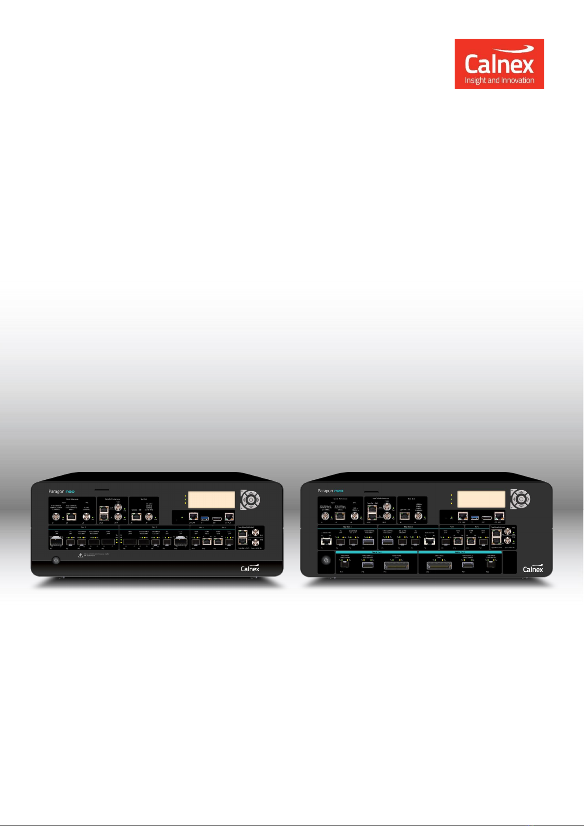
This guide describes all versions of the instrument: Paragon-neo first generation, Paragon-neo second generation,
Paragon-neo R and Paragon-neo PAM4.
Paragon-neo functions (with appropriate options installed):
•Ethernet interface rates of –
-NRZ ports: 100M, 1GbE, 10GbE, 25GbE, 40GbE, 50GbE and 100GbE.
-PAM4 ports: 50GbE, 100GbE, 200GbE and 400GbE.
•PTP timeTransmitter/timeReceiver emulation, impairments, and time error measurements to ITU-T G.826x and
G.827x standards, including Class-C, Class-D and other Enhanced Timing devices.
•PTP and Time of Day message decode and analysis.
•SyncE wander tolerance, transfer and generation testing to ITU-T G.8262.1 and G.8262.
•SyncE jitter tolerance and generation testing to ITU-T G.8262.1 and G.8262. Jitter testing available only on NRZ
interfaces.
•ESMC message generation and measurement to ITU-T G.8264.
•1PPS/ToD generation and measurement.
•Background traffic generation.
1.2 Terminology
This document uses the following definitions:
•Paragon-neo –a general description applying to both Paragon-neo NRZ and Paragon-neo PAM4 instruments.
•Paragon-neo NRZ –an item or description specific to the Paragon-neo NRZ first or second generation
instrument.
•Paragon-neo R –an item or description specific to the Paragon-neo R instrument.
•Paragon-neo PAM4 –an item or description specific to the Paragon-neo PAM4 instrument.

Page | 5
2Installation
The Paragon-neo is bench portable and operates stand-alone in a normal laboratory environment. If the Paragon-
neo is to be mounted in an equipment rack, either use the Calnex supplied rack mounting kit, or the Paragon-neo
can be placed on an appropriately secured and weight rated shelf in the rack.
Always position the equipment with unrestricted access to the AC power connector.
The vents to the left and right sides of the Paragon-neo chassis must always be unimpeded to allow for the cooling
of the internal components (airflow is left to right when looking at the front panel). Ensure that there is at least
75mm unobstructed space on each side of the instrument to allow airflow.
Environmental operating conditions must comply with the specifications in section 2.2.4.
2.1 Supplied Accessories & Paperwork
After unpacking the Paragon-neo, make sure that the accessories below are present. If anything is missing, contact
•Power cord (1)
•Getting Started Guide (1)
•Declaration of Conformity (1)
•CSS Brochure (1)
•Customer Information Sheet (1)
•Calibration Certificate (instruments fitted with Jitter measurement option only) (1)
•Rackmount Instructions (1)
•Packing List (1)
2.2 Specifications and Operating conditions
WARNING:
Use of this equipment in a manner not specified by Calnex Solutions may impair the protection
afforded by the equipment and invalidate the warranty. Note that there are no user-serviceable
parts inside the Paragon-neo. The instrument should be returned to Calnex Solutions for all
repairs. Unauthorized opening of the instrument will invalidate the warranty.
WARNING:
To prevent fire or shock hazard, do not expose the unit to rain or moisture.
WARNING:
To avoid electrical shock:
•Use the only power cord supplied, or one with adequate ratings, and connect only to a
properly grounded power socket outlet. Ensure the power socket outlet is easily accessible
and near the unit.
•Do not open covers. Refer servicing to qualified personnel only.

Page | 6
2.2.1 Dimensions
Paragon-neo: 45cm x 40cm x 17cm (W x D x H).
Cardboard Shipping Carton: 63cm x 60cm x 33cm.
Carry Case: 63cm x 60cm x 33cm.
2.2.2 Weight
Paragon-neo: 13kg (max).
Gross Packed Weight (shipping carton): 25kg (max). Paragon-neo plus Power Cord fitted in Carry Case with
Cardboard Shipping Carton.
Gross Packed Weight (carry case): 24kg (max). Paragon-neo plus Power Cord fitted in Carry Case.
2.2.3 Power Requirements
The unit requires a power source of:
Voltage: 100 –240V AC.
Power: 800W max.
Frequency: 50 –60Hz.
2.2.4 Environmental Conditions
The environmental conditions the instrument is designed to support are as listed below:
•For indoor use only
•Altitude: Operating: ≤2000m
•Operating temp: 0 –40˚C
•Relative Humidity: Operating: ≤90% non-condensing
•Pollution degree of the intended environment: PD2
•Mains supply voltage fluctuations: ±10%
•Overvoltage category: OVC II
2.2.5 Regulatory
CE and EMC (incl. EN-61010, EN-61326, etc.) certified.
•Safety: EN 61010-1:2010 +A1:2019, CAT II
•EMC: EN 61326-1:2021
2.3 Cleaning
If the surface of the Paragon-neo becomes dirty, remove the AC power and clean with a soft lint-free cloth. Never
use flammable liquids to clean the instrument.
2.4 Shipping Packaging
Paragon-neo is supplied in a carrying case. This case is designed and tested specially to protect your Paragon-neo
during transport. Please retain for future use, as transporting in any other packaging will void the instrument
warranty.

Page | 7
2.5 Labels and Disposal Information
The Waste Electrical and Electronic Equipment regulations label indicates that the equipment
should only be disposed of through an approved method. At the end of life please dispose of the
equipment through a recognized and approved scheme fulfilling the local environmental
requirements.
The CE mark indicates that the product meets all the appropriate provisions of the relevant
legislation contained in the European Directives.

Page | 8
3Paragon-neo Front Panels
3.1 First Generation Paragon-neo NRZ Front Panel
First generation Paragon-neo NRZ instruments can be identified by the presence of two CFP4 transceiver ports on
the front panel.
On/Off Switch
Optical Ethernet Ports
SFP (P2, P9)
SFP+/SFP28 (P3, P8)
QSFP+/QSFP28 (P4, P7)
100G CXP (P1, P10)
100G CFP4 (P5, P6)
Optical Ethernet Ports 100M SFP (P11, P14)
Electrical Ethernet Ports 100/1000BASE-T (P12, P13)
Clock Measurement Ports
Balanced (P15)
Unbalanced (P16)
Measurement Ports
1PPS+ToD Balanced (P17)
1PPS Unbalanced (P18)
Diagnostic Ports
(unused) (J12, J13)
Status Display
USB (J11)
LAN (J10)
Reset Switch
Unbalanced Clock
Ref Output (J3)
Ref Outputs
1PPS+ToD Balanced (J4)
1PPS Unbalanced (J6)
Ref Inputs
1PPS+ToD Balanced (J5)
1PPS Unbalanced (J7)
Test Outputs
1PPS+ToD Balanced (J8)
Unbalanced Clock (J9)
Clock Ref Inputs
Unbalanced (J1)
Balanced (J2)
Buttons

Page | 9
3.2 Second Generation Paragon-neo NRZ Front Panel
Second generation Paragon-neo NRZ instruments can be identified by the presence of two high speed electrical
(2.5G/5G/10G) Ethernet ports on the front panel. Second generation instruments do not have CFP4 transceiver
ports.
Diagnostic Ports
(unused) (J12, J13)
Status Display
USB (J11)
LAN (J10)
Reset Switch
Unbalanced
Clock Ref Output (J3)
Ref Outputs
1PPS+ToD Balanced (J4)
1PPS Unbalanced (J6)
Ref Inputs
1PPS+ToD Balanced (J5)
1PPS Unbalanced (J7)
Test Outputs
1PPS+ToD Balanced (J8)
Unbalanced Clock (J9)
Clock Ref Inputs
Unbalanced (J1)
Balanced (J2)
On/Off Switch
NRZ Optical Ethernet Ports
SFP (P2, P7)
SFP28/SFP+ (P3, P6)
QSFP28/QSFP+ (P4, P5)
Clock Measurement Ports
Balanced (P13)
Unbalanced (P15)
Measurement Ports
1PPS+ToD Balanced (P14)
1PPS Unbalanced (P16)
Electrical Ethernet Ports
2.5G/5G/10G (P1, P8)
Optical Ethernet Ports 100M SFP (P9, P12)
Electrical Ethernet Ports 100/1000BASE-T (P10, P11)
Buttons

Page | 10
3.3 Paragon-neo R Front Panel
Paragon-neo R instruments can be identified by the Paragon-neo R logo on the front panel.
Diagnostic Ports
(unused) (J12, J13)
Status Display
USB (J11)
LAN (J10)
Reset Switch
Unbalanced
Clock Ref Output (J3)
Ref Outputs
1PPS+ToD Balanced (J4)
1PPS Unbalanced (J6)
Ref Inputs
1PPS+ToD Balanced (J5)
1PPS Unbalanced (J7)
Test Outputs
1PPS+ToD Balanced (J8)
Unbalanced Clock (J9)
Clock Ref Inputs
Unbalanced (J1)
Balanced (J2)
On/Off Switch
NRZ Optical Ethernet Ports
SFP (P2, P7)
SFP28/SFP+ (P3, P6)
Clock Measurement Ports
Balanced (P13)
Unbalanced (P15)
Measurement Ports
1PPS+ToD Balanced (P14)
1PPS Unbalanced (P16)
Electrical Ethernet Ports
2.5G/5G/10G (P1, P8)
Optical Ethernet Ports 100M SFP (P9, P12)
Electrical Ethernet Ports 100/1000BASE-T (P10, P11)
Buttons

Page | 11
3.4 Paragon-neo PAM4 Front Panel
Paragon-neo PAM4 instruments can be identified by the presence of a second row of PAM4 transceiver ports.
Diagnostic Ports
(unused) (J12, J13)
Status Display
USB (J11)
LAN (J10)
Reset Switch
Unbalanced
Clock Ref Output (J3)
Ref Outputs
1PPS+ToD Balanced (J4)
1PPS Unbalanced (J6)
Ref Inputs
1PPS+ToD Balanced (J5)
1PPS Unbalanced (J7)
Test Outputs
1PPS+ToD Balanced (J8)
Unbalanced Clock (J9)
Clock Ref Inputs
Unbalanced (J1)
Balanced (J2)
On/Off Switch
NRZ Optical Ethernet Ports
SFP (P2, P7)
SFP28/SFP+ (P3, P6)
QSFP28/QSFP+ (P4, P5)
Clock Measurement Ports
Balanced (P13)
Unbalanced (P15)
Measurement Ports
1PPS+ToD Balanced (P14)
1PPS Unbalanced (P16)
Electrical Ethernet Ports
2.5G/5G/10G (P1, P8)
PAM4 Optical Ethernet Ports
SFP56/SFP-DD (P17, P22)
QSFP-DD/QSFP56 (P18, P21)
CFP2 (P19, P20) currently not used
Optical Ethernet Ports 100M SFP (P9, P12)
Electrical Ethernet Ports 100/1000BASE-T (P10, P11)
Buttons

Page | 12
4Front Panel Controls
Paragon-neo NRZ first- and second-generation instruments have different Ethernet port numbers as shown in the
tables below. Paragon-neo NRZ second generation, Paragon-neo R and Paragon-neo PAM4 have consistent ports
numbers for the Ethernet ports. All other ports (reference, measurement, management) have consistent port
numbers across the Paragon-neo family.
4.1 On/Off Switch
Use this button to switch Paragon-neo On or Off. Switch off at the front panel before switching off the AC input on
the rear panel.
4.2 Ethernet Ports
Optical Transceivers
CAUTION
Take care when inserting and removing transceivers from all ports. Excessive insertion and
extraction force, leverage and vertical movement can permanently damage the internal circuitry.
Direct Attach Cables (DACs)
CAUTION
Paragon-neo ports are designed for optical transceivers only. Direct Attach Cables, both active
and passive, are not supported on any ports. Use of Direct Attach Cables can permanently
damage the internal circuitry.
100M/1G Electrical Ethernet ports
100M SFP Ethernet
ports
Paragon-neo NRZ 1st gen:
P11, P14
For connections to 100M NRZ
interfaces on Ethernet devices.
Paragon-neo NRZ 2nd gen, R, PAM4:
P9, P12
100M/1G Electrical
Ethernet ports
Paragon-neo NRZ 1st gen:
P12, P13
For connections to 100M/1G RJ45
electrical interfaces on Ethernet
devices.
Paragon-neo NRZ 2nd gen, R, PAM4:
P10, P11
Note: During a Boundary Clock Relative Time Error test, the Port 1 100M SFP port operates at 1G. Further details
are given in the G.8273.2 BC Conformance Test Guide, document ref CX3009.
2.5G/5G/10G Electrical Ethernet Ports
2.5G/5G/10G
Electrical Ethernet
ports
Paragon-neo NRZ 1st gen:
n/a
Contact Calnex for software support
schedule.
Paragon-neo NRZ 2nd gen, R, PAM4:
P1, P8
1G SFP Ethernet Ports
1G SFP Ethernet ports
Paragon-neo NRZ 1st gen:
P2, P9
For connections to 1G NRZ optical
interfaces on Ethernet devices.
Paragon-neo NRZ 2nd gen, R, PAM4:
P2, P7

Page | 13
SFP+/SFP28 Ethernet Ports
10G SFP+ Ethernet
ports
Paragon-neo NRZ 1st gen:
P3, P8
For connections to 10G NRZ optical
interfaces on Ethernet devices.
Paragon-neo NRZ 2nd gen, R, PAM4:
P3, P6
25G SFP28 Ethernet
ports
Paragon-neo NRZ 1st gen:
P3, P8
For connections to 25G NRZ optical
interfaces on Ethernet devices.
Paragon-neo NRZ 2nd gen, R, PAM4:
P3, P6
QSFP28/QSFP+ Ethernet Ports
40G QSFP+
Ethernet ports
Paragon-neo NRZ 1st gen:
P4, P7
For connections to 40G (4 x 10G)
NRZ optical interfaces on Ethernet
devices.
Paragon-neo R
n/a
Paragon-neo NRZ 2nd gen, PAM4:
P4, P5
100G QSFP28
Ethernet ports
Paragon-neo NRZ 1st gen:
P4, P7
For connections to 100G (4 x 25G)
NRZ optical interfaces on Ethernet
devices.
Paragon-neo R
n/a
Paragon-neo NRZ 2nd gen, PAM4:
P4, P5
100G CXP Ethernet Ports
100G CXP Ethernet
ports
Paragon-neo NRZ 1st gen:
P1, P10
For connections to 100G NRZ
optical interfaces on Ethernet
devices.
Paragon-neo NRZ 2nd gen, R, PAM4:
n/a
100G CFP4 Ethernet Ports P5, P6 –Do Not Connect
100G CFP4
Ethernet ports
Paragon-neo NRZ 1st gen:
P5, P6
Do not connect.
These ports are not used.
Paragon-neo NRZ 2nd gen, R, PAM4:
n/a
SFP56/SFP-DD Ethernet Ports
50G SFP56
Ethernet ports
Paragon-neo NRZ 1st gen, 2nd gen, R:
n/a
For connections to 50G PAM4
optical interfaces on Ethernet
devices.
Paragon-neo PAM4:
P17, P22
100G SFP-DD
Ethernet ports
Paragon-neo NRZ 1st gen, 2nd gen, R:
n/a
For connections to 100G PAM4
optical interfaces on Ethernet
devices.
Paragon-neo PAM4:
P17, P22
Note: PAM4 100G support was first introduced in Paragon-neo Software Revision 11.00.xx.
QSFP56/QSFP-DD Ethernet Ports
200G QSFP56
Ethernet ports
Paragon-neo NRZ 1st gen, 2nd gen, R:
n/a
For connections to 200G PAM4
optical interfaces on Ethernet
devices.
Paragon-neo PAM4:
P18, P21
400G QSFP-DD
Ethernet ports
Paragon-neo NRZ 1st gen, 2nd gen, R:
n/a
For connections to 400G PAM4
optical interfaces on Ethernet
devices.
Paragon-neo PAM4:
P18, P21
CFP2 Ethernet Ports
100G/400G CFP2
Ethernet ports
Paragon-neo NRZ 1st gen, 2nd gen, R:
n/a
Do not connect.
These ports are not used.
Paragon-neo PAM4:
P19, P20

Page | 14
4.3 References Inputs & Outputs
Calnex recommend that all cables carrying reference signals are as short as possible. ITU G.703 Section 19.2
states that 50Ω cables carrying 1PPS signal must be less than 3m length to ensure signal integrity.
Clock Reference Input
RJ48 Balanced
Clock Reference
Input
Paragon-neo NRZ 1st gen:
J2
Balanced clock reference signals (RJ48): E1, T1,
64k+8k, 64k+8k+400.
Pin 1 (Ring), Pin 2 (Tip). All other pins must be left
unconnected.
Max differential input voltage: 3.3V.
AC coupled.
Input impedance:
E1 120Ω differential,
T1 100Ω differential,
64k+8k, 64k+8k+400 120Ω differential.
Paragon-neo NRZ 2nd gen,
R, PAM4:
J2
BNC Unbalanced
Clock Reference
Input
Paragon-neo NRZ 1st gen:
J1
Unbalanced clock reference signals: 2.048MHz,
10MHz, E1.
Max input voltage:
10MHz, 2.048MHz 5Vp-p,
E1 3.3Vp-p.
Input impedance:
2.048MHz 50Ωor High Impedance, AC coupled,
E1 75Ω AC coupled,
10MHz 50Ωor High Impedance, AC coupled.
Paragon-neo NRZ 2nd gen,
R, PAM4:
J1
IMPORTANT
Paragon-neo allows the option to input balanced and unbalanced clock reference signals.
Calnex recommend using an unbalanced clock reference signal (BNC connector J1) for the
best measurement accuracy.
1PPS and ToD Reference Inputs
RJ48 Balanced
1PPS and ToD
Reference Input
Paragon-neo NRZ 1st gen:
J5
Balanced 1PPS and ToD reference input.
Pins 3 (–) and 6 (+) 1PPS balanced input.
Pins 7 (–) and 8 (+) ToD balanced input.
Pins 4 and 5 ground.
All other pins must be left unconnected.
Min input voltage: 0.3V differential.
Max input voltage: 10V differential.
ToD and 1PPS inputs are DC coupled.
Input impedance: 100Ω differential.
Paragon-neo NRZ 2nd gen,
R, PAM4:
J5
BNC Unbalanced
1PPS Reference
Input
Paragon-neo NRZ 1st gen:
J7
Unbalanced 1PPS reference input.
Max input voltage: 5V DC coupled.
Threshold voltage adjustable in the GUI.
Input impedance: 50Ωor High Impedance.
Paragon-neo NRZ 2nd gen,
R, PAM4:
J7
1PPS reference input pulse timing requirements: 100ns minimum pulse width, 500ms maximum pulse width.
IMPORTANT
Paragon-neo allows the option to input balanced and unbalanced 1PPS reference signals. Calnex
recommend using an unbalanced 1PPS reference signal (BNC connector J7) for the best measurement
accuracy.

Page | 15
Unbalanced Clock Reference Output
BNC Unbalanced
Clock Reference
Output
Paragon-neo NRZ 1st gen:
J3
Connection to unbalanced clock reference output:
2.048MHz or 10MHz.
Output voltage:
-1.5/+1.5V High Impedance load,
-0.75/+0.75V 50Ωload.
Output impedance:
2.048MHz 50Ω, AC coupled,
10MHz 50Ω, AC coupled.
Paragon-neo NRZ 2nd gen,
R, PAM4:
J3
1PPS and ToD Reference Outputs
RJ48 Balanced
1PPS and ToD
Reference Output
Paragon-neo NRZ 1st gen:
J4
For connection to the reference input of other pieces
of lab test equipment, or other Paragon-neos. The
output ToD data cannot be modified.
Pins 3 (–) and 6 (+) 1PPS balanced output.
Pins 7 (–) and 8 (+) ToD balanced output.
Pins 4 and 5 ground.
All other pins must be left unconnected.
Output voltage: 2.0V differential, Vcm=2.5Vtyp into
100Ω load, DC coupled.
Output drives 100Ω load.
Paragon-neo NRZ 2nd gen,
R, PAM4:
J4
BNC Unbalanced
1PPS Reference
Output
Paragon-neo NRZ 1st gen:
J6
Connection to unbalanced 1PPS reference output.
Output voltage:
0.6/3.8V High Impedance load,
0/1.8V 50Ωload.
Output impedance: 50Ω DC coupled.
Paragon-neo NRZ 2nd gen,
R, PAM4:
J6
1PPS reference output pulse width: 20ms.
CAUTION
The 1PPS and ToD Reference Output connectors are designed for output only. Care must be taken
when connecting that an input signal is not applied, as this can permanently damage the internal
circuitry.

Page | 16
Test Outputs
RJ48 Balanced
1PPS and ToD
Test Output
Paragon-neo NRZ 1st gen:
J8
For connection to a 1PPS and ToD input of devices
under test. The output ToD data can be modified to
emulate the behavior of a real ToD source.
Pins 3 (–) and 6 (+) 1PPS balanced output.
Pins 7 (–) and 8 (+) ToD balanced output.
Pins 4 and 5 ground.
All other pins must be left unconnected.
Output voltage: 2.0V differential, Vcm=2.5Vtyp into 100Ω
load, DC coupled.
Output drives 100Ω load.
Paragon-neo NRZ 2nd gen,
R, PAM4:
J8
BNC Unbalanced
Clock Test Output
Paragon-neo NRZ 1st gen:
J9
Connection to unbalanced 10MHz clock test output.
Output voltage:
-1.5/+1.5V high impedance load,
-0.6/+0.6V 50Ωload.
Output impedance: 50ΩAC coupled.
Paragon-neo NRZ 2nd gen,
R, PAM4:
J9
1PPS test output pulse width: 20ms.
CAUTION
The 1PPS and ToD Test Output connectors are designed for output only. Care must be taken when
connecting that an input signal is not applied, as this can permanently damage the internal circuitry.

Page | 17
4.4 Measurement Ports
Calnex recommend that all cables carrying measurement signals are as short as possible. ITU G.703 Section 19.2
states that 50Ω cables carrying 1PPS signal must be less than 3m length to ensure signal integrity.
Cable compensation values can be configured in Paragon-neo depending on the measurement running. Typical
cable propagation delay values are 4.9ns/m for single-mode optical cables, 4.94ns/m for multimode optical cables
and 5.1ns/m for electrical cables. Note that these are only typical values and the actual value will differ between
specific cable types, therefore, for the most accurate cable compensation, the actual propagation delay value for a
specific cable should be provided by the cable manufacturer or measured by the user.
Clock Frequency Measurement Inputs
RJ48 Balanced
T1/E1 Clock
Frequency
Measurement Input
Paragon-neo NRZ 1st gen:
P15
Connection to balanced T1/E1 clock frequency
measurement input.
Pins 1 (ring) and 2 (tip) –balanced frequency input.
All other pins must be left unconnected.
Max input voltage: 3.3V differential.
Input impedance:
T1 100Ω differential, AC coupled,
E1 120Ω differential, AC coupled.
Paragon-neo NRZ 2nd gen,
R, PAM4:
P13
BNC Unbalanced
Clock Frequency
Measurement Input
Paragon-neo NRZ 1st gen:
P16
Connection to unbalanced E1 / 2.048MHz / 10MHz /
25MHz clock frequency measurement input.
Max input voltage:
2.048MHz, 10MHz, 25MHz 5Vp-p,
E1 3.3Vp-p.
Input impedance:
2.048MHz, 10MHz, 25MHz 50ΩAC coupled,
E1 75Ω AC coupled.
Paragon-neo NRZ 2nd gen,
R, PAM4:
P15
1PPS and ToD Measurement Inputs
RJ48 Balanced
1PPS and ToD
Measurement
Inputs
Paragon-neo NRZ 1st gen:
P17
Connection to balanced 1PPS and ToD
measurement inputs.
Pins 3(–) and 6(+) 1PPS balanced inputs.
Pins 7(–) and 8(+) ToD balanced inputs.
Pins 4 and 5 ground.
All other pins must be left unconnected.
Min input voltage: 0.3V differential.
Max input voltage: 10V differential.
Input impedance: 100Ω differential DC coupled.
Paragon-neo NRZ 2nd gen,
R, PAM4:
P14
BNC Unbalanced
1PPS Measurement
Input
Paragon-neo NRZ 1st gen:
P18
Connection to balanced 1PPS measurement input.
Max input voltage: 5V DC coupled.
Threshold voltage adjustable in the GUI.
Input impedance: 50Ωor High Impedance.
Paragon-neo NRZ 2nd gen,
R, PAM4:
P16
1PPS measurement pulse timing requirements: 100ns minimum pulse width, 500ms maximum pulse width.
IMPORTANT
Paragon-neo allows the option to input balanced and unbalanced 1PPS measurement signals.
Calnex recommend using the unbalanced 1PPS measurement port (BNC connector P16/P18)
to ensure best measurement accuracy

Page | 18
4.5 Control & Configuration
Status Display
After booting, the Paragon-neo management port IP address is displayed on the LCD Status Display.
Buttons
The buttons to the right of the LCD Status Display are used to configure the Paragon-neo management port IP
address, see section 7 for details.
LAN (J10)
This is for connection to the network or a to a PC. The connection to the Paragon-neo LAN control port (RJ45) is
1GbE.
USB (J11)
This is for firmware upgrades via a memory stick and can also be used to power any USB accessories.
Reset Switch
Using a pointed implement, gently press the RESET button to return the Paragon-neo to its power-on condition.
This resets the IP address to factory default.
Diagnostic Ports J12, J13 –Do Not Connect
Diagnostic Ports
Paragon-neo NRZ 1st gen:
J12, J13
Do not connect. These ports are
reserved for diagnostic use by
Calnex.
Paragon-neo NRZ 2nd gen, R,
PAM4:
J12, J13

Page | 19
5Rear Panel Description
AC Power Input
For connection to supplied AC power using the power cord supplied, or one with adequate ratings. See section
2.2.3 for details of the power requirements.
AC Power Switch
Use this switch to turn the Paragon-neo AC Input On or Off.
GPS Antenna Input & Output
The GPS antenna input and output connections are not used. Do not connect.
High-Speed Data Inputs
The high-speed data input connections are not used. Do not connect.

Page | 20
6Optical Transceivers
Accurate PTP and SyncE timing measurement requires the use of high-quality optical transceivers (user supplied)
with Paragon-neo. Transceivers that exhibit high degrees of timing variability should be avoided.
6.1 Supported NRZ Optical Transceivers
NRZ transceivers generally exhibit low latency asymmetry that is compensated for by Paragon-neo. Most NRZ
optical transceivers can be used for PTP timing and SyncE wander measurements. SyncE Jitter testing requires the
use of specific optical transceivers qualified by Calnex. Qualified transceivers have low inherent jitter and can be
correctly configured by Paragon-neo to make accurate measurements.
For the complete list of Calnex-supported optical transceivers please see the relevant section of the Calnex FAQ
(keyword “optics”) accessed through the support pages at www.calnexsol.com.
6.2 Supported PAM4 Optical Transceivers
PAM4 optical transceivers (50G, 100G, 200G and 400G) typically exhibit variable and asymmetric latencies that
negatively impacts timing measurement accuracy. Therefore, Calnex have qualified specific PAM4 transceivers
that must be used with Paragon-neo.
For the complete list of Calnex-supported optics please see the relevant section of the Calnex FAQ (keyword
“optics”) accessed through the support pages at www.calnexsol.com.
Other manuals for Paragon-neo
1
Table of contents
Other Calnex Test Equipment manuals
Popular Test Equipment manuals by other brands

BIRD
BIRD AT-400 Antenna Tester AT-400 Operator's manual

Silverline
Silverline 196602 quick guide

Fluke
Fluke 730G user manual

Maico
Maico WS 170 L Operating and maintenance instructions

LeCroy
LeCroy WavePro 7 Zi series Getting started manual

Keysight Technologies
Keysight Technologies U3022AM06 User's and service guide