Calnex Sentinel User manual

USER GUIDE
CX3001
User Guide
Sentinel Sync Analyser

CX3001 v7.0 © Calnex Solutions 2
calnexsol.com |
Table of Contents
Sentinel Sync Analyser .............................................................................. 4
1.1 Introduction................................................................................................................................. 4
1.2 Description .................................................................................................................................. 5
1.3 Specifications............................................................................................................................... 8
Safety Instructions.................................................................................. 10
2.1 Introduction............................................................................................................................... 10
2.2 Safety Precautions...................................................................................................................... 10
2.3 Grounding ................................................................................................................................. 11
2.4 Power Switch ............................................................................................................................. 11
2.5 Disposal of Hazardous Material .................................................................................................... 12
2.6 GNSS Antenna Installation .......................................................................................................... 12
Using Sentinel ......................................................................................... 13
3.1 General Operation ...................................................................................................................... 13
3.2 Controls..................................................................................................................................... 15
Configuration settings............................................................................. 16
4.1 Presets...................................................................................................................................... 16
4.2 Mode......................................................................................................................................... 17
4.3 Settings..................................................................................................................................... 17
4.4 Masks........................................................................................................................................ 36
4.5 Health Check ............................................................................................................................. 37
4.6 Data.......................................................................................................................................... 42
4.7 System...................................................................................................................................... 43
Operation................................................................................................. 50
5.1 Measurements ........................................................................................................................... 50
5.2 Saving Measurement Data........................................................................................................... 51
Measurement Result Graph..................................................................... 52
Viewing Mode .......................................................................................... 55
7.1 Masks Table............................................................................................................................... 55
7.2 Measurement Analysis ................................................................................................................ 56
Widgets & Icons ...................................................................................... 57
8.1 Measurement channels ............................................................................................................... 57
8.2 Status icons ............................................................................................................................... 60
8.3 Real Time Marker ....................................................................................................................... 60
Remote Access ........................................................................................ 61
9.1 VNC Access................................................................................................................................ 61
Remote Control ....................................................................................... 62
10.1 Authentication............................................................................................................................ 62
10.2 API Interface Service List ............................................................................................................ 63
10.3 Recovery API Interface Service List .............................................................................................. 78

CX3001 v7.0 © Calnex Solutions 3
calnexsol.com |
Calnex CAT PC Software Guide ............................................................... 81
Preventative Maintenance ...................................................................... 85
12.1 Update Firmware........................................................................................................................ 85
Appendix A: Signal Types............................................................................ 86
Appendix B: Built-in Masks ......................................................................... 87
Appendix C: Reference Material.................................................................. 88
Appendix D: List of Sentinel Log Messages ................................................ 89

Instructions
CX3001 v7.0 © Calnex Solutions 4
calnexsol.com |
Sentinel Sync Analyser
1.1 Introduction
Calnex Sentinel is the all-in-one Synchronisation tester for testing both the legacy PDH/SDH networks and the
newer SyncE, PTP (IEEE1588v2), NTP IP/Ethernet networks for mobile backhaul, data center, financial trading
venues, power utility systems and, indeed, any network requiring Frequency, Phase or Time Synchronisation.
Sentinel measures PTP or clock Time Error (TE) 5G NR or 4G LTE networks that use either ITU-T G.8275.1 Full on
Path support, or ITU-T G.8275.2 Assisted Partial Timing Support (APTS)/Partial Timing Support (PTS), as well as
TE measurements over the air (OTA) by examining the timing signals within the NR or LTE transmission.
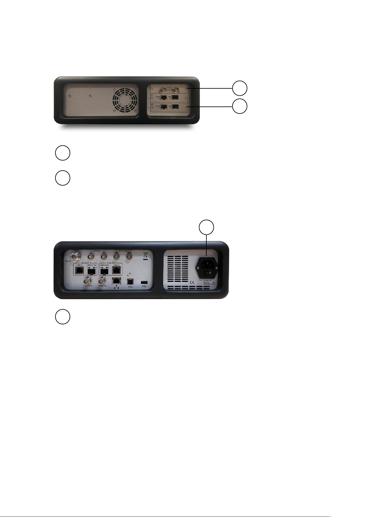
Sentinel is of modular design to allow for flexible configuration and easy future upgrade. It contains three slots
where measurement modules can be fitted. Newer revisions (serial number 400XXX) of Sentinel come with two
licensable PTP measurement channels built in, leaving the other slots free for clock measurement and OTA
modules
Sentinel is designed to simultaneously measure any combination of SyncE, PTP/NTP, E1/T1, 10MHz, 1 PPS, RF air
interface phase and user defined clocks to multiple industry and standards masks.
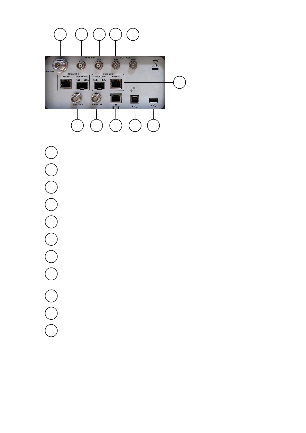
There are four different measurements module types available.
Clock module
•For Recovered clock measurement
•Provides two ports for Frequency, E1/T1 and 1 PPS measurement and analysis.
Packet module
•Emulates one PTP Slave clock on each packet module (maximum of two modules can be fitted)
•Transport protocol level for PTP measurement: UDP/IPv4, UDP/IPv6 or Ethernet
•PTP Multicast and Unicast supported
•PTP message rates up to 128 messages/sec
•PTP packet by packet capture, measurement and analysis of PDV and TE
•PTP TE and PDV measurements based on PTP event message timestamps
•NTP packet by packet capture, measurement and analysis of PDV and TE
•Emulated NTP Client on each module
•SyncE wander generation and measurements to G.8262
•Simultaneous measurement of SyncE and PTP/NTP for measuring Hybrid networks
•1 Ethernet port supporting 100 M / 1GbE interface rates
Packet module (10GbE)
•Identical functionality to packet module
•Maximum of two Ethernet ports supporting 100M / 1GbE / 10GbE interface rates
Over the Air (OTA) module
•Determine absolute timing accuracy of 5G NR gNodeB or 4G LTE eNodeB RF interface
•Frequency range from 350 MHz to 6GHz
Sentinel supports real-time measurements and metric analysis of SyncE and clock TIE/MTIE/TDEV metrics and
Packet PDV, FPP, Packet Distribution, 2 Way TE and 1 PPS TE. Additionally, it supports the measurement of Max
|TE|, cTE and dTE to G.8271.1 and pktSelected 2 Way TE for G.8271.2 APTS/PTS networks.
Sentinel has a built-in high-quality Rubidium clock which can be trained by GNSS (GPS, GLONASS, Galileo, Beidou
and QZSS) or external 1 PPS (Rb- or Cs-Quality). The Rubidium is battery backed up to allow it to be held in
holdover >3 hours, so that Time can be maintained while travelling to the test site.
It is equipped with a large 8.4” colour LCD touch screen, clearly showing graphs of Wander TIE/MTIE/TDEV and
PTP/NTP PDV, Time Error, FPP, MAFE, Packet Distribution and other ITU-T metrics in real time during a
measurement. With an intuitive graphical interface, Sentinel is a user-friendly instrument.

Instructions
CX3001 v7.0 © Calnex Solutions 5
calnexsol.com |
1.2 Description
Front panel
Colour LCD touch screen
Health Check
Opens the Health Check menu.
Settings
Opens the Settings menu
Lock
Lock/Unlock the touch screen
Power
Instrument power on/off button.
Press to switch on and to switch off the instrument. In the Stand-by mode, power is
maintained for the internal rubidium timebase, as long as the mains cable is connected to
the mains outlet.
Start/Stop
Measurement start/stop button
Keypad
Buttons for navigation in the menus displayed on the screen
[Enter] Confirm
1
2
4
6
7
3
5
1
2
3
4
5
6
7

Instructions
CX3001 v7.0 © Calnex Solutions 6
calnexsol.com |
[Exit] Exit from the menu, save the selection, and return to the previous page
[Cancel]
Right Panel
Clock module
2 channels per module, BNC connectors
Packet Module
1 channel per module, RJ45 or SFP connector
Left Panel
Main connection
Power Supply
8
9
10
8
9
10

Instructions
CX3001 v7.0 © Calnex Solutions 7
calnexsol.com |
Antenna
GNSS antenna connector
1 PPS in –TTL / 50
External 1 PPS phase reference input.
1 PPS out –TTL / 50
Internal 1 PPS timing output from Rubidium oscillator.
E1/T1 clock output (MHz)
User settable E1 or T1 clock output, BNC 75.
E1/T1 framed output (Mbit/s)
User settable E1 or T1 framed output, isolated BNC 75.
External reference
Input for precision external reference (1, 5 or 10MHz clock).
Reference signal output
10MHz frequency from the internal reference or the external reference (if selected).
Ethernet network connector
Standard RJ45 connector for connecting the instrument to a PC or LAN using the
10/100BASE-T protocol, enabling remote control over Ethernet.
USB type B connector (for future use)
USB Device port
USB type A connector
USB Host port
10GbE packet module
Up to 2 channels per module, RJ45 or SFP connectors
Accessories delivered with the instrument
•Line power cord
•GNSS Antenna and 20m cable
•User Guide & CAT Analysis software on USB stick
11
12
13
14
15
16
17
18
19
20
21
11
12
13
14
15
16
17
18
19
20
21

Instructions
CX3001 v7.0 © Calnex Solutions 8
calnexsol.com |
1.3 Specifications
General Specifications
Power Supply
•Line Voltage: 100-240V, 50-60Hz, <150W
Environmental Data
•Temperature: Operating: 0°C to 40°C
•Safety: EN 61010-1:2010, CAT II, Pollution degree 2, Measuring category I, CE
•EMC: EN61326-1:2013
Mechanical Data
•Fold-out stand; Shock resistant cabinet
•Dimensions (w x h x d): 320 x 388 x 126 mm (12.6” x 15.3” x 5”)
•Weight: Net <7kg (15lb); Shipping with transport case < 16kg (35lb)
Platform Specifications
•Reference Clock: Built-in Rubidium reference or external reference input 1, 5 or 10MHz
•Display: Colour TFT, 8.4", 800x600 pixels
•Internal Memory: sufficient for > 3 days measurement
Internal Time Base Stability (hold-over)
•Stability Versus Temperature: 20 to 26 °C: <1x10-11 (typ.), -20 to +65°C: <1x10⁻¹⁰ baseplate
•Ageing Rate per 24 h: <5x10-11 per month); <5x10⁻¹⁰ (yearly)
•Warm-up Stability: 12 min to <1x10⁻⁹
•Allan Variance: <2x10-11 (1s); <1x10-11 (10s); <2x10-12 (100s)
GNSS disciplining
•Built-in GNSS module: 12 channels, TRAIM GNSS receiver, high sensitivity
•Supported constellations: GPS, GLONASS, Galileo, Beidou and QZSS
•Frequency accuracy: 2x10-12 averaged over 24 hours
Input Modules
Clock module
•Number of channels: 2 per module
•Connector: BNC, unbalanced
•Frequency: 1 PPS/2s to 200MHz
•Impedance: 75or 1Mselectable
•Voltage Range: from -5V to +5V
•Sensitivity: 60mVpp
•Signal Type: Symmetrical pulse (Clock signal), Unsymmetrical repetitive pulse (Clock signal), HDB3-coded
data (Data signal), AMI B8ZS, B3ZS (Data signal)
Packet module
•Connectors: RJ45 for 10/100/1000BASE-T, SFP 100M/1GbE
•Number of channels: 1 per module
•SyncE Wander measurement Accuracy: 1ns
•PDV measurement accuracy: 5ns
•Time Error Accuracy: +/-75ns with reference to GNSS
10GbE Packet module
•Connectors: RJ45 for 10/100/1000BASE-T, SFP(+) 100M/1GbE/10GbE
•Number of channels: up to 2 per module
•SyncE Wander measurement Accuracy: 1ns
•PDV measurement accuracy: 5ns
•Time Error Accuracy: +/-75ns with reference to GNSS
OTA module
•Connectors: SMA connector for RF antenna

Instructions
CX3001 v7.0 © Calnex Solutions 9
calnexsol.com |
•Number of channels: 1 per module
•Time Error Accuracy: +/-100ns with reference to GNSS
External References
Frequency Reference Input
•Input Frequency: 1MHz, 5MHz or 10MHz
•Voltage Range: 0.1Vrms to 5Vrms
•Impedance: approx. 50
External 1 PPS Timing Input
•Voltage range: 0V to 0.8V (Low), 2V to 3.3V (High) into 50
•Required accuracy: ± 100ns to UTC
GNSS Timing Reference
•Antenna input: N-type connector
•DC-feed: +5V on centre pin to active antenna
Output References
Frequency Reference Output
•Ref. Frequency: 10MHz sine-wave
•Output Levels: 1Vrms in 50
1 PPS Output
•Source: Internal Rubidium oscillator
•Output Level: TTL levels in 50
E1/T1 Output
•Connector: Clock: BNC; Data: isolated BNC
•Frequency: 1.544/2.048MHz, 1.544/2.048Mb/s
•Output Level: Acc. to G703:10; ±1.2V ±10% in 75
Interfaces
USB Device port
•Connector: USB type B
•USB version: 2.0
USB Host port
•Connector: USB type A
•Max supply current: 400mA
•USB version: 2.0
Ethernet
•Communication port: RJ45, 10/100BASE-T
•Protocol: DHCP and FTP server, VNC

Safety Precautions
CX3001 v7.0 © Calnex Solutions 10
calnexsol.com |
Safety Instructions
2.1 Introduction
Read this page carefully before you install and use the instrument.
This instrument has been designed and tested according to safety Class1 requirements of standard IEC/EN
61010-1 and has been supplied in a safe condition. The user of this instrument must have the required
knowledge of it. This knowledge can be gained by thoroughly studying this manual.
This instrument is designed to be used by trained personnel only. The cover of the instrument must only be
removed for repair by Calnex personnel who are aware of the hazards involved. There are no user-serviceable
parts inside the instrument.
If the surface of the Sentinel becomes dirty, remove the AC power and clean with a soft lint-free cloth. Never use
flammable liquids to clean the device.
2.2 Safety Precautions
To ensure the correct and safe operation of this instrument, it is essential that you follow generally accepted
safety procedures in addition to the safety precautions specified in this manual.
Use of this equipment in a manner not specified by Calnex, may impair the protection provided by the equipment.
This equipment is portable and should be lifted and carried by handle only, never use the tilt bail to lift the unit.
In normal operation the openings in the chassis should be not be blocked, to allow for cooling of the internal
components.
Always operate the equipment with unrestricted access to the AC power connector.
Caution and Warning statements
Symbols
Indicates that the user should consult the manual.
Shows where the protective ground terminal is connected inside the
instrument. Never remove or loosen this screw.
If in doubt about Safety
Whenever you suspect that it is unsafe to use the instrument, you must make it inoperative as follows:
•Disconnect the mains cable.
•Clearly mark the instrument to prevent its further operation.
•Contact Calnex customer service.
For example, the instrument is likely to be unsafe if it is visibly damaged.
CAUTION:
Shows where incorrect procedures can
cause damage to, or destruction of
equipment or other property.
WARNING:
Shows a potential danger that requires
correct procedures or practices to prevent
personal injury.

Safety Precautions
CX3001 v7.0 © Calnex Solutions 11
calnexsol.com |
2.3 Grounding
Whenever an instrument is connected to the mains voltage, any grounding fault will make it
potentially dangerous. Before connecting any unit to the mains supply, you must make sure that
the protective ground functions correctly. Only then can a unit be connected to the mains supply
and only by using a three-wire mains cable. No other method of grounding is permitted.
Extension cords must always have a protective ground conductor.
A power supply cord is supplied with the equipment. If the user is obtaining a pluggable power
cord for use with their local power connection the power cord must meet all local safety
requirements, have an integrated safety ground wire and be rated for the power requirements of
the Sentinel.
2.4 Power Switch
This instrument is equipped with a secondary power switch. It disconnects the main power-consuming circuits on
the secondary side of the power supply. Mains voltage is always present on the primary side.
WARNING:
If a unit is moved from a cold to a warm
environment, condensation may cause a
shock hazard. Ensure that the grounding
requirements are strictly met.
WARNING:
Never interrupt the grounding cable. Any
interruption of the protective ground connection
inside or outside the instrument or disconnection
of the protective ground terminal is likely to
make the instrument dangerous.
WARNING:
Always consider the instrument active as soon as it is connected to the primary AC power source
with a mains cable. Disconnection of the mains cable completely cuts off the power supply to the
instrument.

Safety Precautions
CX3001 v7.0 © Calnex Solutions 12
calnexsol.com |
2.5 Disposal of Hazardous Material
This instrument uses a 3V lithium cell to power a Real Time Clock. It is placed in a holder and can be replaced by
qualified personnel who are aware of the hazards involved.
2.6 GNSS Antenna Installation
This instrument is equipped with GNSS receiver which requires GNSS antenna input. This input should be
connected properly and safely to the external GNSS antenna.
WARNING:
Disposal of lithium cells requires special attention. Do not expose them to heat or to excessive
pressure, which may cause the cells to explode. Make sure they are recycled according to local
regulations.
WARNING:
For permanent installation, the GNSS antenna and associated cables require an EMP Protector to be
fitted for safety reasons. The EMP Protector should be professionally fitted as per the
manufacturer’s instructions. These instructions come with the EMP Protector.
Observe all local regulations on the fitting, grounding and specification of lightning or surge
arrestors on the antenna cable.
Disconnect or switch off in-line equipment when installing, checking, disconnecting and connecting
EMP protectors. This includes also the exchange of gas discharge tubes. Keep back from such
activities during thunderstorms. Be aware that only a complete protection system according to IEC
62305-1 can protect your equipment and personnel against the impact of lightning.
This includes an external lightning protection system with air terminal, down conductor and
grounding system and bonding of all incoming and outgoing lines (e.g. protectors for mains, data
and telephone lines) - not RF lines only.
With gas discharge tube protectors take care that the GDT has been properly installed before
putting the equipment into operation.

Using Sentinel
CX3001 v7.0 © Calnex Solutions 13
calnexsol.com |
Using Sentinel
3.1 General Operation
Set-Up
Connect the source(s) under test to the inputs on the Clock or Packet modules
By default, the frequency reference to use is automatically selected. The Rubidium reference is used, unless a
valid external reference is connected to the external reference Freq In connector.
Connect the instrument to the mains supply and turn on the power switch: the instrument switches on
automatically.
An identification screen is displayed, then the main instrument software starts up.

Using Sentinel
CX3001 v7.0 © Calnex Solutions 14
calnexsol.com |
On completion of start-up, the following screen is displayed, with the message Ready at bottom-left of the
screen; the instrument is ready for use (in case of a cold start the message will be Warming Up… and the
Rubidium icon on bottom-right will be yellow).
The Recall Settings option allows previously saved configuration files to be re-loaded, automatically setting up
Sentinel to the state defined in the preset file and then displaying the main operating screen. Selecting the
Manual Setup option moves directly to the main operating screen.
Battery Option
If the Battery Option is present, it can be used for providing power to the internal Rubidium oscillator during
transport to site (Transport Mode). Information about installed options is available in the About page of the
System menu. Also, when the Battery Option is present the corresponding icon in status bar will display
battery charge percentage:
If the Battery Option is installed then upon switching off the instrument, the user is asked if Transport Mode
should be turned on. In Transport Mode, Sentinel will use the battery to keep the internal Rubidium oscillator
powered for up to 3 hours when mains supply is not present.

Using Sentinel
CX3001 v7.0 © Calnex Solutions 15
calnexsol.com |
Note: When in Transport Mode, the battery will not be charged. The battery is only charged when Sentinel is
powered on and running.
Switching off
The instrument is switched off by pressing the button on the front panel. When the indicator light turns on
red the instrument is switched off.
As long as the instrument is connected to the mains supply, the internal Rubidium oscillator is powered up and
retains its characteristics.
Disconnection of the mains cable completely cuts off the power supply to the instrument unless the Battery
Option is installed, in which case only the Rubidium oscillator remains powered.
3.2 Controls
The main screen contains controls to allow simple, ordered Configuration (1) and Operation (2) of Sentinel.
Navigation buttons allow movement between each Measurement Result Graph (3) and change the mode of
Viewing Results (4). The status of the measurement sub system is shown in Widgets and Icons (5) at the
bottom of the screen.
These will be described in detail in the following chapters of the user guide.
(1)
(2)
(3)
(4)
(5)

Using Sentinel
CX3001 v7.0 © Calnex Solutions 16
calnexsol.com |
Configuration settings
Manual configuration of Sentinel is simply a process of working through the tabs on the main screen as detailed
below.
4.1 Presets
Measurement settings can be saved and reloaded later. The user can choose the filename and current Settings
will be saved in a .preset file. This function is especially useful for fast setup in the field.
Factory default settings can be restored using the Restore to Defaults button.

Using Sentinel
CX3001 v7.0 © Calnex Solutions 17
calnexsol.com |
4.2 Mode
The Mode screen allows the Sentinel measurement subsystem to be configured as required for the type of
testing being performed. Sentinel expansion slot channels are labelled A –F and the 10 GbE module is labelled 1
–2. This screen will reflect which modules are installed in Sentinel. The example below shows that one Clock
module, an OTA module and the 10GbE packet module with 2 channels are installed. The user can
enabled/disable channels on this screen according to requirements. Monitor Mode can also be selected through
this screen (two packet ports need to be installed and PDV option needs to be enabled for this option to be
available). Note that for the 4G/5G OTA module, only one OTA measurement type may be selected at a time. For
the 4G OTA module, only OTA-LTE is present.
If a channel is disabled on the Mode screen, this will be reflected in the corresponding Widget on the main
screen. Disabling unused channels simplifies configuration and result viewing by removing these channels from
the configuration and results screen.
4.3 Settings
The settings area contains multiple tabs to configure all the relevant measurement subsystems selected through
the mode screen and some options that are common to all measurement types.
A common set of buttons are displayed permanently on each of the Settings screens. The buttons always have
the following functionality:
OK
Apply all the settings changes that have been made whilst in the settings screens. When applied
return to the main display
Cancel
Cancel all settings changes that have been made to date within the exception of any that have
already been applied using the Apply button
Apply
Apply all settings changes that have been made and remain in the settings screen

Using Sentinel
CX3001 v7.0 © Calnex Solutions 18
calnexsol.com |
Measurement
Common
The Common page is used to define the general characteristics of the measurement.
Start
Defines when the measurement should start and allows the following options
Immediate
Start the measurement as soon as the Start button is pressed
Timer
Start the measurement at the specified time
Start time
Defines start time when Start mode is
Timer
Continuous Measurement
Defines whether the measurement when started should run on a continuous basis. This
results in a series of 24 hours measurements being made. A new measurement is
started each time 00:00 UTC is reached. The last 7 days of measurement data is
retained in the folder named
continuous
within the internal storage. Each day of data is
stored in a folder within the
continuous
folder with a name indicating the day the
measurement started based on UTC time.
Whilst running in this mode it is not possible to measure any metrics e.g. TDEV, MTIE.
No masks will be checked whilst continuous mode is enabled.
Metrics
This disables metric calculation (e.g. TDEV, MTIE) and mask checking during
measurement.
If this option has been selected and metrics are required after a measurement has been
completed, this can be achieved using the Calnex Analysis Tool (CAT) which is supplied
with Sentinel.
Duration
Duration of the measurement. The measurement duration is defined either by the time
entered in the Duration field or by the stop time entered in the Stop time field. If a
duration is entered, the Stop time is updated accordingly, and if a stop time and date
are entered, the measurement duration is updated accordingly
Stop time
Defines stop time when Start mode is
Timer
Estimated Data size
Displays estimated size of file for measurement data. Depending on the configuration, if
the duration exceeds a certain length, the instrument enters Long Term mode. In
Long Term mode only some of the available graphs are displayed and no metrics are
calculated
Sample time
Measurement interval. Signal measurements are made point by point at regular intervals
defined by entry using the virtual keyboard.
33ms
is the default setting to provide 30
TIE samples per second in accordance with the recommendations for wander
measurement equipment in ITU-T O.172
Auto-Restart
The user can define if they want the measurement to restart should there be a power
interruption during the measurement
TIE Mode
This parameter allows the selection of the following measurement modes
TIE
General TIE measurement for every enabled input channel

Using Sentinel
CX3001 v7.0 © Calnex Solutions 19
calnexsol.com |
TIE + 1 PPS TE
All connected 1 PPS signals will measure absolute differential TIE relative to the signal
connected to the reference channel. All other signals measure normal TIE relative to the
selected timebase
TE
This performs the same measurement as
TIE
, but the initial phase offset of each signal
is not compensated for
Diff TIE
All connected signals (including SyncE) will measure differential TIE relative to the signal
connected to the reference channel. See Diff TIE Reference setting
Diff TE
This performs the same measurement as
Diff TIE
, but the initial phase offset of each
signal is not compensated for
Diff T(I)E reference
Drop-down list for selection of the input channel or internal reference to be used as
reference when TIE Mode is
Diff TIE, Diff TE
or
TIE + 1 PPS TE
G.8271.1 TE Mask Value
Sets the absolute value for the G.8271.1 Max|TE| mask. This is user defined and
configures the Pass/Fail limit for TE measurements when that mask is selected
Note: In all cases, even a delayed start, the measurement is not made until the Start button is pressed.
Timebase
The Timebase page provides the following settings:
Timebase Reference
Internal
Use the internal Rubidium as the reference for measurements
External
Use an external reference for measurements
Auto
Use an external reference if connected to the Freq In connector
and if not use the internal Rubidium reference.
Measurement Start Behavior
Start even if Timebase Reference is not ready
This will start a measurement even if the internal Rubidium
reference is not fully warmed up
Wait till Timebase Reference is ready
The measurement will wait until the reference is fully ready and
warmed
Abort if Timebase Reference is not ready
The measurement will fail if the reference is not ready to proceed
Internal Reference Disciplining Mode
Never
Disable disciplining. The internal Rubidium will remain in free
running mode and will never discipline to GNSS or an external
reference even if available.
Not during measurement
Enable disciplining, but do not use it during measurement
Always
Enable disciplining always, the Rubidium reference will not
discipline if a suitable reference is not available.
Internal Reference Disciplining Source
GNSS
Use internal GNSS receiver.

Using Sentinel
CX3001 v7.0 © Calnex Solutions 20
calnexsol.com |
If the last disciplining was less than 1 week ago, Sentinel should
be disciplined for at least 6 hours, otherwise Sentinel should be
disciplined for at least 12 hours
Ext 1 PPS (GPS/Rb Quality Source)
Use 1 PPS signal from external GPS receiver or external Rb
quality atomic clock
Ext 1 PPS (Cs Quality Source)
Use 1 PPS signal from external Cs quality atomic clock
Note: Sentinel will only discipline if the disciplining source selected is producing a valid disciplining output and
so Internal Reference Disciplining Mode can be left to
Always
even if the source is not available. If
the source is re-connected during a measurement, then there may be a phase shift in the timebase
reference.
GNSS
This page allows selection of GNSS constellation and displays general GNSS information received: position,
altitude, number of satellites that receiver is locked to, antenna status and signal levels for all visible satellites.
The top constellation selection determines whether GPS is used and if GPS is selected, whether QZSS is also
used. If GPS is not selected, a constellation must be selected in the lower selection area. For multi-constellation
operation, select GPS or GPS and QZSS and a secondary constellation.
Press Apply. This will cause the GNSS module to reset and begin a new site survey using the new
constellation(s).
NOTE: Changing constellations will cause the Rb timebase to unlock and it may experience a step input from
the GNSS 1 PPS output. It is recommended that Sentinel remains disciplining to GNSS for at least 6
hours after changing constellations. This period should be at least 12 hours if Sentinel has not been
disciplined for more than a week.
Satellite SNR status is shown in the same colour as the text in the constellation name. The Locked to status
displays the total number of locked satellites over all selected constellations.
GPS, Galileo and Beidou satellites transmit information that allows Sentinel to calculate the number of leap
seconds that have occurred, and this is used to determine the offset between TAI and UTC. The Leap seconds
value is updated automatically whenever this information is received.
GLONASS does not transmit leap second information and the Leap seconds must be manually entered if the
current value is not correct. PTP uses TAI as the time base for its timestamps and if the Leap seconds value is
incorrect it will show as whole seconds of offset in the FwdPDV, RevPDV and 2WayTE graphs.
Survey status shows progress of the GNSS receiver site survey.
Reset Module allows the GNSS receiver to be reset.
Antenna Delay setting is used to compensate for antenna cable length.
NOTE: Support for multiple GNSS constellations is dependent on the correct revision of GNSS module hardware
being fitted. If, after installing R9.1, no additional constellations can be configured then please submit a problem
report to [email protected] requesting information on whether multi-constellation operation can be added.
Table of contents
Other Calnex Test Equipment manuals