Calpeda MPC User manual

Pompe autoadescanti per piscine
Self-priming swimming pool pumps
Selbstansaugende Schwimmbadpumpen
Pompes autoamorçantes pour piscines
Bombas autoaspirantes para piscinas
Själv-evakuerande poolpumpar
Zelfaanzuigende zwembadpompen
ë‡ÏÓÁ‡ÎË‚‡˛˘ËÂÒfl ̇ÒÓÒ˚ ‰Îfl ·‡ÒÒÂÈÌÓ‚
自吸式泳池泵
MPC
ISTRUZIONI ORIGINALI PER L’USO Pagina 2 Italiano
OPERATING INSTRUCTIONS Page 10 English
BETRIEBSANLEITUNG Seite 18 Deutsch
INSTRUCTIONS POUR L’UTILISATION Page 26 Français
INSTRUCCIONES DE USO Página 34 Español
DRIFT/INSTALLATIONSANVISNINGAR Sidan 42 Svenska
BEDIENINGSVOORSCHRIFT Pagina 50 Nederlands
àÌÒÚÛ͈ËË ÔÓ ˝ÍÒÔÎÛ‡Ú‡ˆËË ëÚ. 58 êÛÒÒÍËÈ
安装使用手册 页码 66 中文
MPC Rev20.indd 1MPC Rev20.indd 1 23/07/21 16:0123/07/21 16:01

IT
Pagina 2 / 80 MPC Rev20 - Istruzioni originali
ILPRESENTE MANUALE ISTRUZIONI È PROPRIETÀ
DI CALPEDA S.p.A. OGNI RIPRODUZIONE, ANCHE
PARZIALE, È VIETATA.
1. INFORMAZIONI GENERALI
Prima di utilizzare il prodotto leggere attentamente
le avvertenze e le istruzioni riportate in questo
manuale, che deve essere conservato per una futura
consultazione.
La lingua originale di redazione è l’italiano, che farà
fede in caso di difformità nelle traduzioni.
Il manuale è parte integrante dell’apparecchio come
residuo essenziale di sicurezza e deve essere
conservato no allo smantellamento nale del prodotto.
L’acquirente può richiedere copia del manuale in
caso di smarrimento contattando Calpeda S.p.A. e
specicando il tipo di prodotto riportato sull’etichetta
della macchina (Rif. 2.3 Marcatura).
In caso di modiche, manomissioni o alterazioni
dell’apparecchio o parti di esso non autorizzate dal
fabbricante, la “dichiarazione CE” perde di validità e
con essa anche la garanzia.
L'apparecchio può essere
utilizzato da bambini di età non
inferiore a 8 anni e da persone con
ridotte capacità siche, sensoriali
o mentali, o prive di esperienza
o della necessaria conoscenza,
purchè sotto sorveglianza oppure
dopo che le stesse abbiano
ricevuto istruzioni relative all'uso
sicuro dell'apparecchio e alla
comprensione dei pericoli ad esso
inerenti. I bambini non devono
giocare con l'apparecchio.
La pulizia e la manutenzione
destinata ad essere effettuata
dall'utilizzatore non deve essere
effettuata da bambini senza
sorveglianza.
Leggere attentamente la sezione
installazione dove è riportata:
-
la massima prevalenza strutturale
ammessa nel corpo pompa
espressa (capitolo 3.1).
- il tipo e la sezione del cavo di
alimentazione (capitolo 6.5).
- il tipo di protezione elettrica da
installare (capitolo 6.5).
1.1. Simbologia utilizzata
Per migliorare la comprensione si utilizzano i simboli/
pittogrammi sotto riportati con i relativi signicati.
Informazioni ed avvertenze che devono
essere rispettate, altrimenti sono causa
di danneggiamenti all’apparecchio o
compromettono la sicurezza del personale.
Informazioni ed avvertenze di carattere elettrico
il cui mancato rispetto può danneggiare
l’apparecchio o compromettere la sicurezza
del personale.
i
Indicazioni di note e avvertimenti per la
corretta gestione dell’apparecchio e dei suoi
componenti.
Interventi che possono essere svolti
dall’utilizzatore nale dell’apparecchio. Previa
lettura delle istruzioni, e il responsabile per
il suo mantenimento in condizioni di utilizzo
normali. È autorizzato a fare operazioni di
manutenzione ordinaria.
Interventi che devono essere svolti da un
elettricista qualicato abilitato a tutti gli
interventi di natura elettrica di manutenzione
e di riparazione, e in grado di operare in
presenza di tensione elettrica.
Interventi che devono essere svolti da un
tecnico qualicato in grado di utilizzare
correttamente l’apparecchio in condizioni
normali, abilitato a tutti gli interventi di natura
meccanica di manutenzione, di regolazione e
di riparazione.
Indica l’obbligo di uso di dispositivi di protezione
individuale - protezione delle mani.
OFF Interventi che devono essere svolti con
l’apparecchio spento e scollegato dalle fonti di
energia.
ON Interventi che devono essere svolti con
l’apparecchio acceso.
1.2. Ragione sociale e indirizzo del Fabbricante
Ragione sociale: Calpeda S.p.A.
Indirizzo: Via Roggia di Mezzo, 39
36050 Montorso Vicentino - Vicenza / Italia
www.calpeda.it
INDICE
1. INFORMAZIONI GENERALI ..........................2
2. DESCRIZIONE TECNICA...............................3
3. CARATTERISTICHE TECNICHE ...................3
4. SICUREZZA....................................................3
5. TRASPORTO E MOVIMENTAZIONE.............4
6. INSTALLAZIONE ............................................4
7. AVVIO E IMPIEGO .........................................5
8. MANUTENZIONE ...........................................6
9. SMALTIMENTO ..............................................8
10. RICAMBI.........................................................8
11. DENOMINAZIONE DELLE PARTI..................8
12. RICERCA GUASTI..........................................9
13 Pompa sotto il livello dell’acqua....................73
14 Pompa sopra il livello dell’acqua...................75
15 Disegno per lo smontaggio ed il rimontaggio 77
Dichiarazione di conformità ...................................80
MPC Rev20.indd 2MPC Rev20.indd 2 23/07/21 16:0123/07/21 16:01

IT
MPC Rev20 - Istruzioni originali Pagina 3 / 80
1.3. Operatori autorizzati
Il prodotto è rivolto a operatori esperti divisi tra
utilizzatori nali del prodotto e tecnici specializzati
(vedi simboli sopra).
i
E’ vietato per l’utilizzatore nale eseguire
operazioni riservate ai tecnici specializzati. Il
fabbricante non risponde di danni derivati dalla
mancata osservanza di questo divieto.
1.4. Garanzia
Per la garanzia sui prodotti fare riferimento alle
condizioni generali di vendita.
i
La garanzia include sostituzione o riparazione
GRATUITA delle parti difettose (riconosciute
dal fabbricante).
La garanzia dell’apparecchio decade:
- Qualora l’uso dello stesso non sia conforme alle
istruzioni e norme descritte nel presente manuale.
- Nel caso di modiche o variazioni apportate
arbitrariamente senza autorizzazione del Fabbricante
(vedi par. 1.5).
- Nel caso di interventi di assistenza tecnica eseguiti
da personale non autorizzato dal Fabbricante.
- Nel caso di mancata manutenzione prevista nel
presente manuale.
1.5. Servizio di supporto tecnico
Qualsiasi ulteriore informazione sulla documentazione,
sui servizi di assistenza e sulle parti dell’apparecchio,
può essere richiesta a Calpeda S.p.A. (vedi paragrafo
1.2).
2. DESCRIZIONE TECNICA
Elettropompe autoadescanti per piscine con preltro
incorporato e motore isolato dall'acqua.
La pompa è costruita con materiali plastici di altissima
qualità, resistenti all'erosione da sabbia ed alla
corrosione.
Con diffusore in acciaio inossidabile.
Base appoggio pompe.
2.1. Uso previsto
Per acqua pulita o leggermente sporca con corpi solidi
in sospensione, con la temperatura massima di 60 °C.
2.2. Uso scorretto ragionevolmente prevedibile
L’apparecchio è stato progettato e costruito
esclusivamente per l’uso descritto nel par. 2.1.
È assolutamente vietato l’impiego
dell’apparecchio per usi impropri, e modalità di
uso non previste dal presente manuale.
L’utilizzo improprio del prodotto deteriora le
caratteristiche di sicurezza e di efcienza
dell’apparecchio, Calpeda non può essere
ritenuta responsabile per guasti o infortuni dovuti
all’inosservanza dei divieti sopracitati.
2.3. Marcatura
Di seguito una copia della targhetta di identicazione
presente sull’involucro esterno della pompa.
0 Fabricante
1 Tipo de bomba
2 Capacidad
3 Altura
4 Potencia nominal
5 Tension nominale
6 Frecuencia
7 Courant nominale
8
Velocidad de rotación
9 Factor de servicio
10
Clase de aislamiento
11 Certicaciones
12 AAAA Año de
fabricación
12 XXXX Nº de serie
13 Peso
14 Notas
15 Tension
16 % carico
17
Factor de potencia
18 Rendimiento
19 Protección
20 Eciencia motor
21 Eciencia bomba
22 Condensadores
XXXXXXX
Q min/max X/X m3/h
IEC 60034-1 IECX/X
AAAAXXXXX
XXX
XXX
XXX
H max/min X/X m
ESCC2900 MEI≥ XX η
XX kg
IP XX
n XXXX/min
V
XXX
XXX
XXX
%
XXX
XXX
XXX
cos
XXX
XXX
XXX
230∆/400Y V3~50Hz (XX μF) X/X A
XXXXXXXX
S1 l.cl. X
XX kW (XXHp) S.F.
1
0
2
3
21
4
5
15
16
11
13
19
20
22
6
11
7
9
10
12
8
18
17
14
Montorso (VI) Italy IT 00142630243
Made in Italy
3. CARATTERISTICHE TECNICHE
3.1. Dati tecnici
Dimensioni di ingombro e pesi (vedi catalogo).
Velocità nominale 2900/3450 rpm
Protezione IP X4 (IP 55 Special construction)
Tensione di alimentazione/ Frequenza:
- no a 240V 1~ 50/60 Hz
- no a 480V 3~ 50/60 Hz
Vericare che la frequenza e la tensione di rete
sia idonea alle caratteristiche elettriche indicate in
targhetta.
I dati elettrici riportati in targhetta si riferiscono alla
potenza nominale del motore.
Pressione sonora: < 70 dB (A). MPC7: 72 dB (A).
Avviamenti/ora max.: n. 10 ad intervalli regolari.
Pressione nale massima ammessa nel corpo pompa:
25 m (2,5 bar).
Pressione massima in aspirazione: PN (Pa) - Hmax (Pa).
3.2. Ambiente in cui viene posizionata la pompa
Elettropompe previste per luoghi aerati e protetti dalle
intemperie con temperatura massima ambiente di
40°C.
4. SICUREZZA
4.1. Norme comportamentali generiche
Prima di utilizzare il prodotto è necessario
conoscere tutte le indicazioni riguardanti la
sicurezza.
Si deve leggere attentamente e seguire tutte le
istruzioni tecniche, di funzionamento e le indicazioni
qui contenute per i differenti passaggi: dal trasporto
allo smaltimento nale.
I tecnici specializzati sono tenuti al rispetto dei
regolamenti, regolamentazioni, norme e leggi del
paese in cui la pompa è venduta. L’apparecchio è
conforme alle vigenti norme di sicurezza.
L’uso improprio può comunque provocare danni a
persone, cose o animali.
Il fabbricante declina ogni responsabilità in caso di tali
danni o da uso in condizioni diverse da quelle indicate
in targa e nelle presenti istruzioni.
MPC Rev20.indd 3MPC Rev20.indd 3 23/07/21 16:0123/07/21 16:01

IT
Pagina 4 / 80 MPC Rev20 - Istruzioni originali
i
Rispettare la cadenza degli interventi di
manutenzione e la tempestiva sostituzione
dei pezzi danneggiati o usurati, permette
all’apparecchio di lavorare sempre nelle migliori
condizioni. Usare solo ed esclusivamente
pezzi di ricambio originali forniti da CALPEDA
S.p.A.o da un distributore autorizzato.
Non rimuovere o alterare le targhe apposte dal
fabbricante sull’apparecchio.
L’apparecchio non deve essere messo in funzione in
caso di difetti o parti danneggiate.
Le operazioni di manutenzione ordinaria e
straordinaria, che prevedono uno smontaggio
anche parziale dell’apparecchio, devono
essere effettuate solo dopo aver interrotto
l’alimentazione dell’apparecchio stesso.
4.2. Dispositivi di sicurezza
L’apparecchio è costituito da una scocca esterna che
impedisce contatti con gli organi interni e gli elementi
in tensione.
4.3. Rischi residui
L’apparecchio, per progettazione e destinazione d’uso
(rispetto uso previsto e norme di sicurezza), non
presenta rischi residui.
4.4. Segnaletica di sicurezza e informazione
Per questo tipo di prodotto non è prevista segnaletica
sul prodotto.
4.5. Dispositivi di protezione individuale (DPI)
Nelle fasi di installazione avviamento e manutenzione si
consiglia agli operatori autorizzati di valutare, quali siano
i dispositivi idonei al lavori descritti.
Nelle operazioni di manutenzione ordinaria e
straordinaria, è previsto l’uso dei guanti per la protezione
delle mani.
Segnale DPI obbligatori
PROTEZIONE DELLE MANI
(guanti per la protezione da rischio chimico,
termico e meccanico)
5. TRASPORTO E MOVIMENTAZIONE
Il prodotto è imballato per mantenere integro il
contenuto.
Durante il trasporto evitare di sovrapporre pesi
eccessivi. Assicurarsi che durante il trasporto la
scatola non sia libera di muoversi.
Non sono necessari particolari mezzi per trasportare
l’apparecchio imballato.
I mezzi per trasportare l’apparecchio imballato, devono
essere adeguati alle dimensioni e ai pesi del prodotto
scelto (vedi dimensioni di ingombro a catalogo).
5.1. Movimentazione
Movimentare con cura l’imballo, che non deve subire
urti.
Si deve evitare di sovrapporre agli imballi altro
materiale che potrebbe deteriorare la pompa.
Se il peso supera i 25 Kg l’imballo deve essere
sollevato da due persone contemporaneamente.
6. INSTALLAZIONE
6.1. Dimensioni di ingombro
Per le dimensioni di ingombro dell’apparecchio (vedi
catalogo).
6.2. Requisiti ambientali e dimensioni del luogo
di installazione
Il cliente deve predisporre il luogo di installazione in
modo adeguato alla corretta installazione e in coerenza
alle esigenze costruttive della stessa (allacciamenti
elettrico, ecc...).
L’ambiente in cui installare l’apparecchio deve avere i
requisiti del paragrafo 3.2.
È assolutamente vietata l’installazione e la messa in
servizio della macchina in ambienti con atmosfera
potenzialmente esplosiva.
6.3. Disimballaggio
i
Vericare che l’apparecchio non sia stato
danneggiato durante il trasporto.
Il materiale d’imballo, una volta disimballata la
macchina, dovrà essere eliminato e/o riutilizzato
secondo le norme vigenti nel Paese di destinazione
dell’apparecchio.
6.4. Installazione
Le pompe MPC Compact Pool sono previste
per luoghi aerati e protetti dalle intemperie, per
l’installazione con l’asse del rotore orizzontale e piedi
di appoggio in basso.
Installare la pompa il più vicino possibile alla fonte di
aspirazione.
Nel caso di piscina, installare l’elettropompa
ad almeno 3 m dal bordo vasca. Per l’impiego
come pompa portatile all’aperto, prevedere
una adeguata protezione e montare la pompa
su una base isolante di almeno 100 mm di
altezza. Osservare il capitolo 6.5.
Prevedere attorno all’elettropompa spazio per
la ventilazione del motore, per ispezioni, per
controllare la libera rotazione (con cacciavite) e, con
alimentazione trifase, il senso di rotazione (a vista)
dell’albero, per l’estrazione del ltro, per il riempimento
e lo svuotamento del corpo pompa (g. 1).
Fig. 1 Spazio minimo per manutenzione (mm)
6.4.1. Tubazioni
Prevedere il diametro in modo che la velocità del
liquido non superi 1,5 m/s nell’aspirazione ed i
3 m/s nella mandata.
Il diametro delle tubazioni non deve essere inferiore al
diametro delle bocche della pompa.
Estrazione
ltro Smontaggio motore
Controllo
rotazione
albero
VentilazioneScarico
Riempimento
MPC Rev20.indd 4MPC Rev20.indd 4 23/07/21 16:0123/07/21 16:01

IT
MPC Rev20 - Istruzioni originali Pagina 5 / 80
ATTENZIONE: prima di collegare le tubazioni
assicurarsi della loro pulizia interna.
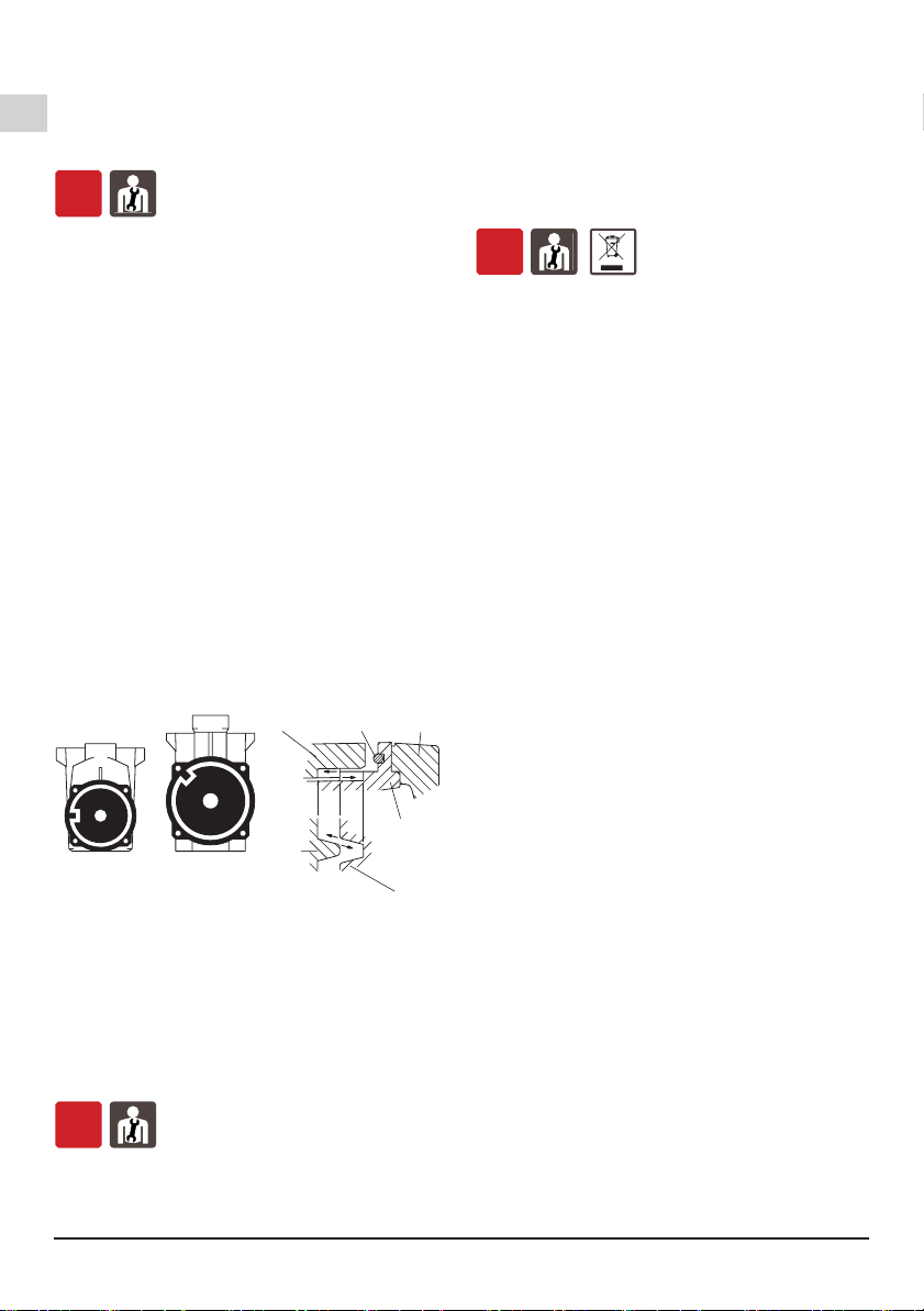
Una quantità concentrata di sabbia con una
granulometria maggiore del gioco radiale tra girante
ed anello di tenuta in acciaio inossidabile (circa 1 mm)
può causare una precoce usura ed una diminuzione
delle prestazioni della pompa di circa il 10%.
Nel caso di prova di tenuta delle tubazioni ad una
pressione superiore a 2,5 bar escludere la pompa
(chiudere le saracinesche prima e dopo la pompa).
6.4.2. Collegamento dei tubi
Impiegare tubi o raccordi di materiale plastico. Per
il collegamento alle bocche lettate della pompa
usare un sigillante per lettature su materiali plastici
(esempio: Loctite 5331).
Il nastro Teon non é raccomandato. Non usare
canapa.
ATTENZIONE: evitare un serraggio eccessivo di
tubi o raccordi nelle bocche lettate. Serrare i tubi
o i raccordi solo quanto basta per assicurare la tenuta.
Un serraggio eccessivo può danneggiare la
pompa.
Nel caso di collegamento di un tubo metallico applicare
alla bocca della pompa un raccordo a bocchettone di
materiale plastico. La giunzione di materiali dissimili
può causare corrosione o rotture per espansioni e
contrazioni termiche non uniformi.
Ancorare le tubazioni su propri appoggi e collegarle in
modo che non trasmettano forze, tensioni e vibrazioni
alla pompa. Il loro peso e le loro dilatazioni termiche
non devono gravare sulla pompa.
Il collegamento in tensione delle tubazioni può
causare rotture o deformazioni del corpo pompa con
perdita della tenuta.
6.4.3. Tubazione aspirante
La tubazione aspirante deve essere a perfetta tenuta
contro l’entrata d’aria.
Nelle installazioni sse con la pompa sotto il livello
dell’acqua (funzionamento sotto battente) (capitolo
13., g. 7) inserire una saracinesca nella condotta di
arrivo ed una nella tubazione di mandata per isolare la
pompa dall’impianto.
Nelle installazioni sse con la pompa sopra il livello
dell’acqua (funzionamento in aspirazione), con più
tubi aspiranti (per skimmers, scarico di fondo, attacco
per pulitore del fondo) collegare ad un collettore tutti i
tubi con una propria saracinesca. Per quanto possibile
disporre i tubi ed il collettore sotto il livello dell’acqua
e raggiungere la pompa con un solo tubo verticale
(vedere capitolo 13., gura 8b e capitolo 7.2.3.).
Nelle installazioni sse per piscine evitare altezze di
aspirazione superiori a 3 m rispetto allo scarico dal
fondo. Con altezze di aspirazione superiori a 1,5 m
inserire una valvola di non ritorno (accessibile) nel
tubo di aspirazione dal fondo.
Negli impieghi con tubi essibili montare in
aspirazione un tubo essibile con spirale di rinforzo
per evitare restringimenti dovuti alla depressione in
aspirazione.
6.4.4. Tubazione di mandata
Nella tubazione di mandata installare una saracinesca
per regolare portata e prevalenza.
Installare un indicatore di pressione (manometro).
6.5. Collegamento elettrico
OFF
Il collegamento elettrico deve essere eseguito
da un elettricista qualicato nel rispetto delle
prescrizioni locali.
Seguire le norme di sicurezza.
Eseguire il collegamento a terra. Collegare il
conduttore di protezione al morsetto contrassegnato
con il simbolo .
Confrontare la frequenza e la tensione di rete con i
dati di targa e collegare i conduttori di alimentazione
ai morsetti secondo il corrispondente schema riportato
all’interno del coperchio della scatola morsetti.
ATTENZIONE: non fare mai cadere una
rondella o altre parti metalliche nel
passaggio cavi interno tra scatola morsetti
e statore. Se accade, smontare il motore e
recuperare la parte caduta.
Se la scatola morsetti è munita di pressacavo usare
un cavo di alimentazione essibile tipo H07 RN-F
con
sezione del cavo pari o superiore (cap. 16 TAB 1)
.
Schema elettrico
(cap. 17)
.
Se la scatola morsetti è munita di anello di tenuta
effettuare il collegamento attraverso tubo.
Per l’uso in una piscina, vasche da giardino o posti
similari, nel circuito di alimentazione deve essere
installato un interruttore differenziale con una
corrente residua (IΔN) ≤ 30 mA.
Installare un dispositivo per la onnipolare
disinserzione dalla rete (interruttore per scollegare
la pompa dall’alimentazione) con una distanza di
apertura dei contatti di almeno 3 mm.
Con alimentazione trifase installare un adeguato
salvamotore con curva D come da corrente di targa.
Le elettropompe monofasi MPCM, sono fornite con
condensatore collegato ai morsetti e (per 220-240 V -
50 Hz) con termoprotettore inserito.
In Austria le pompe da utilizzare per piscine e vasche
da giardino, dotate di una linea di allacciamento ssa,
devono essere alimentate secondo ÖVE B/EN 60555
parte 1-3, mediante un trasformatore di separazione
certicato ÖVE, laddove la tensione nominale
secondaria non deve superare i 230 V.
ATTENZIONE: Quando la pompa è alimentata
con un variatore di frequenza, la frequenza
minima non deve scendere al di sotto di 25 Hz
e in ogni caso la prevalenza della pompa non
dovrà mai essere inferiore a 3 m.
7. AVVIO E IMPIEGO
7.1. Controlli prima dell’accensione
L’apparecchio non deve essere messo infunzione in
presenza di parti danneggiate.
7.2. Primo avviamento
OFF
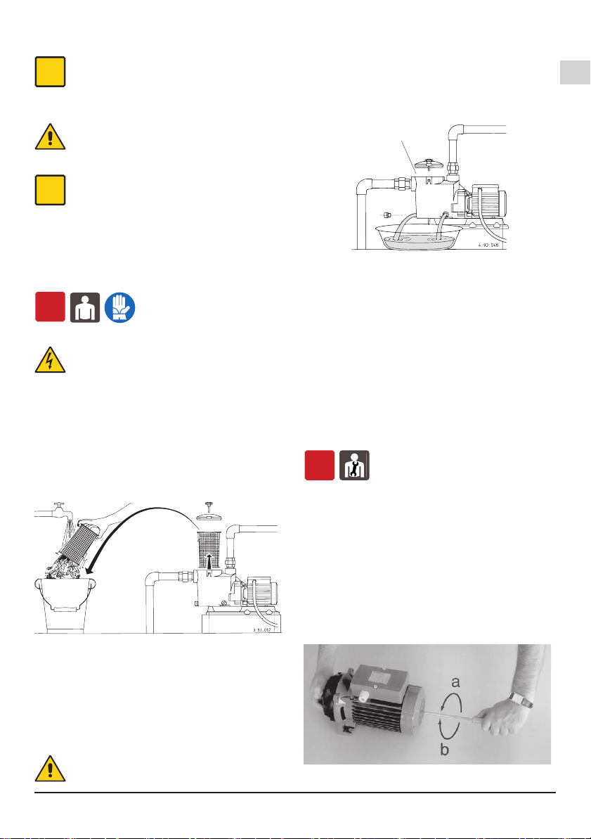
7.2.1. Controllo senso di rotazione
ATTENZIONE: al primo avviamento, con alimentazione
trifase vericare il senso di rotazione.
Con i tipi trifasi MPC 51, 61, 71 eseguire la verica
del senso di rotazione prima di immettere acqua nella
pompa (vedere anche il capitolo 8.4.).
Accertarsi prima che l’albero giri a mano. Per questo
scopo utilizzare l’intaglio per cacciavite sull’estremità
MPC Rev20.indd 5MPC Rev20.indd 5 23/07/21 16:0123/07/21 16:01

IT
Pagina 6 / 80 MPC Rev20 - Istruzioni originali
dell’albero lato ventilazione. Ruotare l’albero a mano
solo nel senso indicato dalle frecce sul corpo pompa.
Non avviare il motore se l’albero risulta bloccato.
La girante potrebbe svitarsi se bloccata e se in
questa condizione il motore si avvia con senso di
rotazione inverso. La rotazione inversa è dannosa
anche per la tenuta meccanica.
Avviare per pochi giri il motore e controllare che il
senso di rotazione corrisponda a quello indicato dalle
frecce sul corpo pompa: orario guardando il motore dal
lato ventola. In caso contrario, togliere l’alimentazione
elettrica e invertire fra loro i collegamenti di due fasi.
7.2.2. Riempimento
ATTENZIONE: evitare il funzionamento a secco.
Con la pompa sotto il livello d’acqua nella vasca
(funzionamento sotto battente), riempire la pompa
aprendo lentamente e completamente la saracinesca
nella condotta di arrivo, tenendo aperta la saracinesca
in mandata per far uscire l’aria.
Con la pompa sopra il livello dell’acqua da sollevare
(funzionamento in aspirazione), riempire la pompa con
acqua no al livello della bocca aspirante, attraverso
l’apertura sul ltro togliendo il coperchio (g. 2).
Fig. 2 Riempimento
Dopo l’avviamento, controllare che l’elettropompa
lavori nel suo campo di prestazioni e che non venga
superata la corrente assorbita indicata in targa. In caso
contrario regolare la saracinesca in mandata.
Evitare il funzionamento prolungato con sara-
cinesca chiusa.
7.2.3. Autoadescamento
(Capacità di aspirazione dell’aria nel tubo aspirante
all’avviamento con la pompa installata sopra il
livello dell’acqua; quando il tubo aspirante, senza
valvola di fondo, non può essere riempito manualmente
di liquido).
Le altezze di aspirazione massime ed i tempi di
autoadescamento minimi (vedere il foglio delle
caratteristiche) si ottengono con motore elettrico
normale (n=2900 1/min), con acqua degasata a
temperatura non superiore a 25 °C e con un solo
tubo aspirante dello stesso diametro della bocca di
aspirazione della pompa.
Condizioni per l’autoadescamento:
• Corpo pompa riempito d’acqua no al livello della
bocca aspirante prima dell’avviamento.
Con altezza di aspirazione superiore a 1,5-2 m,
in mancanza di valvola di fondo o di valvola di
non ritorno nel tubo di aspirazione, il riempimento
deve essere ripetuto prima di ogni avviamento.
• Saracinesche in aspirazione e mandata
completamente aperte e tubi senza ostruzioni.
• Filtro a cesto non intasato.
• Tubo aspirante con i raccordi a perfetta tenuta
contro l’entrata d’aria e bene immerso nell’acqua da
sollevare.
• Guarnizione O-ring sul corpo ltro e tenuta meccanica
a perfetta tenuta contro l’entrata d’aria (correttamente
montate, pulite e non danneggiate).
• Viti a manopola del coperchio ltro e tappo di scarico
del corpo ltro serrati a mano per impedire entrate
d’aria.
• Tubo di mandata senza valvola di non ritorno e con un
tratto verticale libero di almeno 80 cm sopra la bocca
della pompa. Con altezza di aspirazione inferiore a 2
m il tratto verticale sulla pompa può essere di 50 cm.
Con altezza di aspirazione inferiore ad 1 m può
essere montata una curva direttamente sulla bocca
di mandata, senza un tratto di tubo verticale.
Trascorso il tempo previsto accertarsi (attraverso
il coperchio trasparente sul ltro) dell’avvenuto
autoadescamento e della regolarità del usso d’acqua.
Se la pompa non si autoadesca vericare tutte le
suddette condizioni e ripristinarle o rimediare
dove necessario.
Ripetere l’operazione di autoadescamento dopo aver
riempito il corpo pompa con acqua fredda.
Evitare il funzionamento prolungato con pompa
non adescata o con un tubo aspirante non
immerso nell’acqua (a causa dell’abbassamento del
livello dell’acqua nella piscina).
Nel caso di abbassamento del livello dell’acqua
sotto gli skimmers o altre bocchette aspiranti (per
lo svuotamento della vasca) tenere aperta solo la
saracinesca del tubo per l’aspirazione dal fondo.
7.3. SPEGNIMENTO
ON
L’apparecchio deve essere spento in ogni caso
in cui vi fossero anomalie di funzionamento.
(vedi ricerca guasti).
Il prodotto è progettato per un funzionamento continuo,
lo spegnimento avviene solamente scollegando
l’alimentazione mediante i previsti sistemi di sgancio
(vedi par. “6.5 Collegamento elettrico”).
8. MANUTENZIONE
Prima di ogni intervento è obbligatorio mettere
l’apparecchio fuori servizio scollegando ogni fonte di
energia.
Se necessario rivolgersi ad elettricista o tecnico
esperto.
Ogni operazione di manutenzione, pulizia o
riparazione effettuata con l’impianto elettrico
sotto tensione, può causare gravi incidenti,
anche mortali, alle persone.
Se il cavo di alimentazione è danneggiato, esso
deve essere sostituito dal costruttore o dal suo
servizio assistenza tecnica o comunque da
una persona con qualica similare, in modo da
prevenire ogni rischio.
Nel caso di manutenzioni straordinarie, o di interventi
di manutenzione che necessitano lo smontaggio di
parti dell’apparecchio, il manutentore deve essere un
tecnico qualicato in grado di leggere e comprendere
schemi e disegni.
MPC Rev20.indd 6MPC Rev20.indd 6 23/07/21 16:0123/07/21 16:01

IT
MPC Rev20 - Istruzioni originali Pagina 7 / 80
È opportuno tenere un registro di tutti gli interventi
effettuati.
i
Durante la manutenzione deve essere
posta particolare attenzione al ne di evitare
l’introduzione o l’immissione in circuito di
corpi estranei, anche di piccole dimensioni,
che possano causare un malfunzionamento e
compromettere la sicurezza dell’apparecchio.
Evitare di eseguire qualsiasi operazione a mani
nude. Utilizzare i guanti anti taglio, e resistenti
all’acqua, per lo smontaggio e la pulizia del
ltro o in altri particolari dove si rendessero
necessari.
i
Durante le operazioni di manutenzione non
deve essere presente personale estraneo.
Le operazioni di manutenzione non descritte in questo
manuale devono essere eseguite solamente da
personale specializzato inviato dalla CALPEDA S.p.A..
Per ulteriore informazioni tecniche riguardanti l’utilizzo
o la manutenzione dell’apparecchio, contattare
CALPEDA S.p.A..
8.1. Manutenzione ordinaria
OFF
I motori collegati direttamente alla rete tramite
interruttori termici possono avviarsi automaticamente.
Prima di ogni intervento di manutenzione
togliere l’alimentazione elettrica e assicurarsi
che la pompa non rischi di essere messa sotto
tensione per inavvertenza.
Ispezionare e pulire periodicamente il cestello
preltro. La frequenza delle pulizie dipende dal tempo
di funzionamento della pompa, dall’ambiente circostante
la vasca, dal vento (per le piscine scoperte) e dalla
frequentazione (numero e comportamento dei bagnanti).
Con la pompa sotto il livello dell’acqua, prima
dello smontaggio del coperchio ltro chiudere le
saracinesche in aspirazione e mandata.
Il preltro è facilmente estraibile togliendo il coperchio
ltro (g. 3).
Fig. 3 Estrazione e pulizia ltro
ATTENZIONE: non lubricare con olio la
guarnizione O-ring. Per la pulizia del coperchio
trasparente usare solo acqua e sapone neutro.
Non usare solventi.
Dopo la pulizia rimettere il ltro nella sua posizione.
Riempire d’acqua no al livello della bocca aspirante
(vedere capitolo 7.2.2.). Assestare il coperchio con la
guarnizione nella sua sede sul corpo pompa e serrare
uniformemente a fondo le viti a manopola.
I prodotti disinfettanti o chimici per il
trattamento dell’acqua non devono venire
aggiunti direttamente nella pompa.
Pericolo di reazioni ed esalazioni dannose per la
salute. Rischio di corrosione nelle condizioni di acqua
stagnante (e con l’aumento della temperatura e la
diminuzione del valore pH).
Se la pompa rimane inattiva per lunghi periodi o
se esiste il pericolo di gelo, deve essere svuotata
completamente togliendo i due tappi di scarico con le
guarnizioni O-ring riutilizzabili (g. 4).
Fig. 4 Scarico
Serrare i tappi di scarico a mano. Non usare pinze
o altri utensili. Eventualmente usare pinze solo per
svitare. Un serraggio con forza eccessiva può causare
rotture.
ATTENZIONE: dopo lunga inattività, prima di
rimettere in marcia il gruppo, riempire di acqua
il corpo pompa e controllare con cacciavite che
l’albero non sia bloccato da incrostazioni o da altre
cause. Se l’albero risulta bloccato, smontare il motore
e rimuovere la causa.
8.2. Smontaggio dall’impianto
Prima dello smontaggio chiudere le saracinesche in
aspirazione e mandata.
8.3. Smontaggio della pompa
OFF
Prima dello smontaggio svuotare il corpo pompa
(vedere g. 4 e capitolo 13.). Per lo smontaggio e il
rimontaggio osservare la costruzione sul disegno in
sezione (capitolo 15.).
Per rimuovere il motore con il raccordo (32.00) dal
corpo pompa (14.00), togliere le viti (14.24), i dadi
(14.28) e le rosette (14.29) e fare leva con due
cacciaviti tra borchie diametralmente opposte.
Per smontare la girante (28.00) inserire un cac-ciavite
a lama larga nell’apposito intaglio sulla estremità
opposta dell’albero (78.00). Bloccare la girante con
una mano e svitarla ruotando l’albero con il cacciavite
in senso antiorario con azione torsionale di entrambi
le mani (g. 5a).
Fig. 5 Smontaggio (a) e rimontaggio (b) girante
Entrata aria
MPC Rev20.indd 7MPC Rev20.indd 7 23/07/21 16:0123/07/21 16:01

IT
Pagina 8 / 80 MPC Rev20 - Istruzioni originali
Se non è possibile bloccare o girare l’albero con
cacciavite, togliere la calotta (90.00) e la ventola
(88.00) e svitare la girante tenendo bloccato l’albero
con una chiave adatta. Assieme alla girante si smonta
la parte rotante della tenuta meccanica (36.00).
8.4. Rimontaggio
OFF
Nel caso di sostituzione della tenuta meccanica
(36.00) montare la parte rotante della tenuta sul
mozzo della girante (28.00) spingendo la molla
no allo spallamento frontale in modo che risulti poi
correttamente compressa. Lubricare con acqua la
tenuta meccanica.
ATTENZIONE: con i tipi trifasi, per evitare lo
svitamento (e la rottura) della girante nel caso di
avviamento con senso di rotazione invertito, pulire
l’estremità lettata dell’albero e applicare sulla metà
anteriore del tratto lettato Loctite 243.
In mancanza del prodotto frenaletti eseguire la verica
del senso di rotazione prima di immettere acqua nella
pompa (per evitare lo svitamento causato dalla forza
resistente dell’acqua nel caso di rotazione inversa).
Montare la girante sull’albero tenendola ferma con
una mano e avvitando l’albero in senso orario con
cacciavite no a bloccare la girante sullo spalla-
mento di arresto. Con questa operazione si mettono
a contatto le superci frontali della tenuta meccanica
senza farle strisciare fra loro (g. 5b).
Pulire con acqua la guarnizione O-ring (14.20) e le
superci di tenuta con le quali viene a contatto.
Al rimontaggio del gruppo motore con girante fare
attenzione che il riferimento sporgente all’interno
del corpo pompa (14.00) si inserisca nell’apposita
feritoia sul coperchio diffusore (27.00) (g. 6).
4.93.149
MPC
11
, 21, 31, 41
MPC
51, 61, 71
14.00 14.20 32.00
27.00
14.00
27.00
Fig. 6 Riferimenti per il montaggio corpo pompa
(14.00) - coperchio diffusore (27.00)
ATTENZIONE: per evitare perdite di tenuta o rotture
per difettoso allineamento e tensioni con-centrate, le
viti (14.24) con i dadi (14.28) devono essere serrate
uniformemente con manovre alternate a croce su
posizioni diametralmente opposte. Coppia di serraggio
viti (14.24): 7 Nm.
8.5.
Pompe con protezione IP55 (esecuzioni speciali).
OFF
Per assicurare sempre il grado di protezione IP55 si
raccomanda che:
- All'atto della messa in funzione l'operatore abbia
cura di controllare il perfetto collocamento della
guarnizione tra basetta e copribasetta. Se il cavo
di linea è di piccola sezione assicurare la tenuta del
pressacavo con una opportuna guaina.
- In caso di smontaggio dei coperchi del motore, si
abbia cura di ripristinare la guarnizione esistente
usando il sigillante LOCTITE tipo 510 od equivalenti,
ove presente, e di controllare il perfetto collocamento
degli anelli di tenuta sull'albero.
9. SMALTIMENTO
OFF
Direttiva europea
2012/19/EU (WEEE)
La demolizione dell’apparecchio deve essere afdata
ad aziende specializzate nella rottamazione di prodotti
metallici, per denire attentamente come procedere.
Per lo smaltimento devono essere seguite le
disposizioni di legge in vigore nel Paese in cui avviene
lo smantellamento, oltre che quanto previsto dalle
leggi internazionali per la protezione ambientale.
10. RICAMBI
10.1. Modalità di richiesta dei ricambi
Nelle eventuali richieste di parti di ricambio precisare
il numero di posizione nel disegno in sezione ed i dati
di targa.
L’ordine può essere inviato a CALPEDA S.p.A. tramite
telefono, fax, e-mail.
11. DENOMINAZIONE DELLE PARTI
Nr. Denominazione
14.00 Corpo pompa
14.14 Tappo
14.15 O-ring
14.20 O-ring
14.24 Vite
14.28 Dado
14.29 Rosetta
15.00 Coperchio ltro
15.04 O-ring
15.12 Vite a manopola
15.16 Dado quadro
15.50 Filtro a cesto
27.00 Coperchio diffusore
27.04 Imbuto diffusore
27.08 O-ring
28.00 Girante
28.12 Anello di arresto
36.00 Tenuta meccanica
70.00 Lanterna di raccordo
73.00 Cuscinetto
73.08 V-ring lato pompa
76.00 Carcassa con avvolg.
76.16 Appoggio
76.30 Base appoggio
76.30 Dado
78.00 Albero-rotore
81.00 Cuscinetto
82.00 Coperchio motore
82.04 Molla di compensaz.
82.08 Vite
88.00 Ventola
90.00 Calotta
90.04 Vite
92.00 Tirante
98.00 Coperchio scat. mors.
Con riserva di modiche.
MPC Rev20.indd 8MPC Rev20.indd 8 23/07/21 16:0123/07/21 16:01

IT
MPC Rev20 - Istruzioni originali Pagina 9 / 80
12. RICERCA GUASTI
OFF
ATTENZIONE: togliere la tensione di alimentazione prima di effettuare qualsiasi manovra.
Non far girare pompa e motore a secco nemmeno per un breve periodo.
Attenersi scrupolosamente alle nostre istruzioni per l’uso, se necessario rivolgersi ad un centro
assistenza autorizzato.
INCONVENIENTI
PROBABILI CAUSE POSSIBILI RIMEDI
1)
Il motore non si
avvia
a) Alimentazione elettrica non idonea
b) Collegamenti elettrici non corretti
c) Intervento del dispositivo di protezione
da sovraccarico del motore
d) Fusibili bruciati o difettosi
e) Albero bloccato
f) Se le cause di cui sopra sono già state
vericate, il motore potrebbe essere in
avaria
a) Vericare che la frequenza e la tensione di rete sia idonea alle
caratteristiche elettriche indicate in targhetta
b) Collegare correttamente il cavo di alimentazione alla morsettiera.
Vericare che la protezione termica sia impostata correttamente (vedi
dati sulla targhetta motore) e accertarsi che il collegamento del quadro
elettrico a monte del motore sia stato eseguito in modo corretto
c) Controllare l’alimentazione elettrica e accertarsi che l’albero della
pompa giri liberamente. Vericare che la taratura della protezione
termica sia stata eseguita correttamente (vedi targhetta motore)
d) Sostituire i fusibili, vericare l’alimentazione elettrica e quanto riportato
in a) e c)
e) Rimuovere le cause di bloccaggio come indicato in “Pompa bloccata”
f)
Riparare o sostituire il motore rivolgendosi ad un centro assistenza autorizzato
2)
Pompa
bloccata
a) Prolungati periodi di inattività con
formazione di ossido all’interno della
pompa
b) Ingresso di corpi solidi nella girante
della pompa
c) Cuscinetti bloccati
a) Lo sbloccaggio delle elettropompe monoblocco di piccola taglia si può
effettuare con un cacciavite agendo sull’apposito intaglio ricavato nella
parte posteriore dell’albero. Per gruppi di dimensioni maggiori si può
imprimere la rotazione direttamente dall’albero pompa o dal giunto (si
ricorda ancora di togliere prima l’alimentazione elettrica) o rivolgersi ad
un centro assistenza autorizzato
b) Se si è in grado, smontare il corpo pompa e rimuovere i corpi solidi
estranei all’interno della girante, se necessario rivolgersi a ad un centro
assistenza autorizzato
c) Nel caso si siano danneggiati i cuscinetti, sostituirli o se necessario
rivolgersi ad un centro assistenza autorizzato
3)
La pompa
funziona ma
non fornisce
acqua
a)
Possibile ingresso di aria da connessioni
del tubo di aspirazione, dai tappi di scarico
o riempimento della pompa oppure dalle
guarnizioni del tubo in aspirazione
b) Valvola di fondo otturata o tubo di
aspirazione non completamente
immerso nel liquido
c) Filtro in aspirazione otturato
a) Vericare quale particolare non è a tenuta e sigillare in modo più
efcace la connessione
b) Pulire o sostituire la valvola di fondo e impiegare un tubo di aspirazione
idoneo all’applicazione
c) Pulire il ltro, se necessario sostituirlo. Vedere anche punto 2a)
4)
Portata
insufciente
a) Tubazioni ed accessori con diametro
troppo piccolo che causano eccessive
perdite di carico
b) Presenza di depositi o corpi solidi nei
passaggi interni della girante
c) Girante deteriorata
d)
Rasamenti di girante e corpo pompa usurati
e) Viscosità eccessiva del liquido pompato
(se di natura diversa dall’acqua)
f) Senso di rotazione errato
g) Altezza di aspirazione eccessiva rispetto
alla capacità aspirante della pompa
h)
Eccessiva lunghezza del tubo di aspirazione
a) Usare tubi e accessori idonei all’impiego
b) Pulire la girante ed installare un ltro in aspirazione per evitare l’ingresso
di altri corpi solidi
c) Sostituire la girante, se necessario rivolgersi ad un centro assistenza
autorizzato
d) Sostituire la girante e il corpo pompa
e) La pompa non è idonea
f) Invertire i collegamenti elettrici nella morsettiera o nel quadro elettrico
g) Provare a chiudere parzialmente la saracinesca in mandata e/o
diminuire il dislivello tra pompa e liquido in aspirazione
h) Avvicinare la pompa al bacino di aspirazione in modo da usare
una tubazione più corta. Se necessario, adottare una tubazione di
aspirazione di diametro maggiore
5)
Rumore e
vibrazioni
della pompa
a) Parte rotante sbilanciata
b) Cuscinetti usurati
c) Pompa e tubazioni non ssate
saldamente
d) Portata troppo elevata per il diametro
della tubazione di mandata
e) Funzionamento in cavitazione
f) Alimentazione elettrica squilibrata
a) Vericare che corpi solidi non ostruiscano la girante
b) Sostituire i cuscinetti
c) Ancorare adeguatamente le tubazioni di aspirazione e mandata
d) Usare diametri superiori o ridurre la portata della pompa
e) Ridurre la portata agendo sulla saracinesca in mandata e/o impiegare
tubi con diametro interno maggiore. Vedere anche il punto 4h)
f) Vericare che la tensione di rete sia idonea
6)
Perdita dalla
tenuta
meccanica
a) La tenuta meccanica ha funzionato a
secco o si è incollata
b) Tenuta meccanica rigata per la presenza
di parti abrasive nel liquido pompato
c) Tenuta meccanica non idonea al tipo di
applicazione
d) Leggero gocciolamento iniziale durante
il riempimento o al primo avviamento
Nei casi a), b) e c), sostituire la tenuta, se necessario rivolgersi ad un
centro assistenza autorizzato
a) Accertarsi che il corpo pompa (e il tubo di aspirazione se la pompa
non è autoadescante) siano riempiti di liquido e che tutta l’aria sia stata
evacuata. Vedere anche il punto 5e)
b) Installare un ltro in aspirazione e impiegare una tenuta adatta alle
caratteristiche del liquido da pompare
c) Scegliere una tenuta con caratteristiche idonee al tipo di impiego
d) Aspettare che la tenuta si assesti con la rotazione dell’albero. Se il
problema persiste, vedere i punti 6a), 6b) o 6c) oppure rivolgersi ad un
centro assistenza autorizzato
MPC Rev20.indd 9MPC Rev20.indd 9 23/07/21 16:0123/07/21 16:01

EN
Page 10 / 80 MPC Rev20 - Operating Instructions
THIS INSTRUCTION MANUAL IS THE PROPERTY
OF CALPEDA S.P.A. ANY REPRODUCTION, EVEN
IF PARTIAL, IS FORBIDDEN
1. GENERAL INFORMATION
Before using the product carefully read the information
contained in this instruction manual, the manual should
be kept for future reference.
Italian is the original language of this instruction
manual, this language is the reference language in
case of discrepancies in the translations.
This manual is part of the essential safety requirement
and must be retained until the product is nally de-
commissioned.
The customer, in case of loss, can request a copy
of the manual by contacting Calpeda S.p.A. or their
agent, specifying the type of product data shown on
the label of the machine (see 2.3 Marking)
Any changes, alterations or modications made to the
product or part of it, not authorized by the manufacturer,
will revoke the “CE declaration” and warranty.
This appliance should not be
operated by children younger
than 8 years, people with reduced
physical, sensory or mental
capacities, or inexperienced
people who are not familiar with
the product, unless they are given
close supervision or instructions
on how to use it safely and are
made aware by a responsible
person of the dangers its use
might entail.
Children must not play with the
appliance.
It is the user's responsibility to
clean and maintain the appliance.
Children should never clean or
maintain it unless they are given
supervision.
Read carefully the installation
section which sets forth:
- The maximum permissible
structural working pressure
(Chapter 3.1).
- The type and section of the
power cable (Chapter 6.5).
- The type of electrical protection
to be installed (Chapter 6.5).
1.1. Symbols
To improve the understanding of the manual, below are
indicated the symbols used with the related meaning.
Information and warnings that must be
observed, otherwise there is a risk that the
machine could damage or compromise
personnel safety.
The failure to observe electrical information
and warnings, could damage the machine or
compromise personnel safety.
i
Notes and warnings for the correct management
of the machine and its parts.
Operations that could be performed by the nal
user. After carefully reading of the instructions,
is responsible for maintenance under normal
conditions. They are authorized to affect
standard maintenance operations.
Operations that must be performed by a
qualied electrician. Specialized technician
authorised to affect all electrical operations
including maintenance. They are able to
operate with in the presence of high voltages.
Operations that must be done performed by
a qualied technician. Specialized technician
able to install the device, under normal
conditions, working during “maintenance”,
and allowed to do electrical and mechanical
interventions for maintenance. They must
be capable of executing simple electrical
and mechanical operations related to the
maintenance of the device.
Indicates that it is mandatory to use individual
protection devices.
OFF Operations that must be done with the device
switched off and disconnected from the power
supply.
ON Operations that must be done with the device
switched on.
SUMMARY
1. GENERAL INFORMATION........................... 10
2. TECHNICAL DESCRIPTION........................ 11
3. TECHNICAL FEATURES.............................. 11
4. SAFETY........................................................ 11
5. TRANSPORTATION AND HANDLING .........12
6. INSTALLATION.............................................12
7. STARTUP AND OPERATION ....................... 13
8. MAINTENANCE............................................14
9. DISPOSAL....................................................16
10. SPARE PARTS .............................................16
11. ESIGNATION OF PARTS ............................. 16
12. TROUBLESHOOTING..................................17
13 Pump located below the water level ............. 73
14 Pump located above the water level.............75
15 Drawing for dismantling and assembly ......... 77
Declaration of conformity.......................................80
MPC Rev20.indd 10MPC Rev20.indd 10 23/07/21 16:0123/07/21 16:01

EN
MPC Rev20 - Operating Instructions Page 11 / 80
1.2. Manufacturer name and address
Manufacturer name: Calpeda S.p.A.
Address: Via Roggia di Mezzo, 39
36050 Montorso Vicentino - Vicenza / Italia
www.calpeda.it
1.3. Authorized operators
The product is intended for use by expert operators
divided into end users and specialized technicians.
(see the symbols above).
i
It’s forbidden, for the end user, carry out
operations which must be done only by
specialized technicians. The manufacturer
declines any liability for damage related to the
non-compliance of this warning.
1.4. Warranty
For the product warranty refer to the general terms and
conditions of sale.
i
The warranty covers only the replacement and
the repair of the defective parts of the goods
(recognized by the manufacturer).
The Warranty will not be considered in the following
cases:
- Whenever the use of the device does not conform
to the instructions and information described in this
manual.
- In case of changes or variations made without
authorization of the manufacturer.
- In case of technical interventions executed by a non-
authorized personnel.
- In case of failing to carry out adequate maintenance.
1.5. Technical assistance
Any further information about the documentation,
technical assistance and spare parts, shall be
requested from: Calpeda S.p.A. (paragraph 1.2).
2. TECHNICAL DESCRIPTION
Self-priming swimming pool pumps with built-in
strainer.
The pump is made with high quality plastic materials,
corrosion and sand erosion resistant.
With stainless steel diffuser.
Base-plate kit.
2.1. Intended use
For clean or slightly dirty water with solids in
suspension, with a maximum temperature of 60 °C.
2.2. Improper use
The device is designed and built only for the purpose
described in paragraph 2.1.
Improper use of the device is forbidden, as is
use under conditions other than those indicated
in these instructions.
Improper use of the product reduces the safety and
the efciency of the device, Calpeda shall not be
responsible for failure or accident due to improper use.
2.3. Marking
The following picture is a copy of the name-plate that is
on the external case of the pump.
0 Manufacturer
1 Type
2 Delivery
3 Head
4 Rated power
5 Supply voltage
6 Frequency
7 Nom. motor current
8 Rotation speed rpm
9 Operation Duty
10 Insul. class
11 Certications
12 AAAA Year of
manufacture
12 XXXX Serial number
13 Weight
14 Notes
15 Voltage
16 % Load
17 Power factor
18 Efciency
19 Protection
20 Motor Efciency
21 Pump Efciency
22 Capacitor
XXXXXXX
Q min/max X/X m3/h
IEC 60034-1 IECX/X
AAAAXXXXX
XXX
XXX
XXX
H max/min X/X m
ESCC2900 MEI≥ XX η
XX kg
IP XX
n XXXX/min
V
XXX
XXX
XXX
%
XXX
XXX
XXX
cos
XXX
XXX
XXX
230∆/400Y V3~50Hz (XX μF) X/X A
XXXXXXXX
S1 l.cl. X
XX kW (XXHp) S.F.
1
0
2
3
21
4
5
15
16
11
13
19
20
22
6
11
7
9
10
12
8
18
17
14
Montorso (VI) Italy IT 00142630243
Made in Italy
3. TECHNICAL FEATURES
3.1. Technical data
Dimensions and weight (see technical catalogue).
Nominal speed 2900/3450 rpm
Protection IPX4 (IP 55 Special construction)
Supply voltage / Frequency:
- up to 240V 1~ 50/60 Hz
- up to 480V 3~ 50/60 Hz
Check that the mains frequency and voltage
correspond to the electrical characteristics shown on
the indicator plate.
The electric data marked on the label are referred to
the nominal power of the motor.
Sound pressure: < 70 dB (A). MPC7: 72 dB (A).
Maximum starts/hour: 10 at regular intervals.
Maximum permissible pressure in the pump casing: 25
m (2,5 bar).
The max. inlet water pressure: PN (Pa) - Hmax (Pa).
3.2. Operating conditions
Installation in well ventilated location protected from
the weather, with a maximum ambient temperature of
40 °C.
4. SAFETY
4.1. General provisions
Before using the product it is necessary to
know all the safety indications.
Carefully read all operating instructions and the
indications dened for the different steps: from
transportation to disposal.
The specialized technicians must carefully comply
with all applicable standards and laws, including local
regulations of the country where the pump is sold.
The device has been built in conformity with the current
safety laws. The improper use could damage people,
animals and objects.
The manufacturer declines any liability in the event of
damage due to improper use or use under conditions
other than those indicated on the name-plate and in
MPC Rev20.indd 11MPC Rev20.indd 11 23/07/21 16:0123/07/21 16:01

EN
Page 12 / 80 MPC Rev20 - Operating Instructions
these instructions.
i
Follow the routine maintenance schedules and
the promptly replace damaged parts, this will
allows the device to work in the best conditions.
Use only original spare parts provided from Calpeda
S.p.A or from an authorized distributor.
Don’t remove or change the labels placed on
the device.
Do not start the device in case of defects or damaged
parts. Maintenance operations, requiring full or partial
disassembly of the device, must be done only
after disconnection from the supply.
4.2. Safety devices
The device has an external case that prevents any
contact with internal parts.
4.3. Residual risks
The appliance, designed for use, when used in-line
with the design and safety rules, doesn’t have residual
risks.
4.4. Information and Safety signals
For this kind of product there will not be any signals
on the product.
4.5. Individual protection devices
During installation, starting and maintenance it is
suggested to the authorized operators to consider
the use of individual protection devices suitable for
described activities.
During ordinary and extraordinary maintenance
interventions, safety gloves are required.
Signal individual protection device
HAND PROTECTION
(gloves for protection against chemical,
thermal and mechanical risks).
5. TRANSPORTATION AND HANDLING
The product is packed to maintain the content intact.
During transportation avoid to stack excessive weights.
Ensure that during the transportation the box cannot
move.
It is not necessary to use any special vehicle to
transport the packaged device.
The transport vehicles must comply, for the weight and
dimensions, with the chosen product (see technical
catalogue dimensions and weights).
5.1. Handling
Handle with care, the packages must not receive
impacts.
Avoid to impact onto the package materials that could
damage the pump.
If the weight exceeds 25 Kg the package must be
handled by two person at the same time.
6. INSTALLATION
6.1. Dimensions
For the dimensions of the device (see technical
catalogue).
6.2. Ambient requirements and installation site
dimensions
The customer has to prepare the installation site in
order to guarantee the right installation and in order to
fulll the device requirements (electrical supply, etc...).
The place where the device will be installed must fulll
the requirements in the paragraph 3.2.
It's Absolutely forbidden to install the machine in an
environment with potentially explosive atmosphere.
6.3. Unpacking
i
Inspect the device in order to check any
damages which may have occurred during
transportation.
Package material, once removed, must be discarded/
recycled according to local laws of the destination
country.
6.4. Installation
The MPC Compact Pool pumps must be installed in
well ventilated locations protected from the weather,
with the rotor axis horizontal and feet downwards.
Place the pump as close as practicable to the suction
source.
To reduce the risk of electric shock install the
pump at least 3 m from the inside walls of a
swimming pool. For use as a pump in outdoor
locations provide suitable protection and mount
the pump on an insulating base of at least 100
mm height. Follow section 6.5.
Provide space around the unit for motor ventilation,
easier inspection, removal of the strainer basket,
lling and draining the pump and checking (with a
screwdriver) for free rotation of the shaft (g. 1). With
three-phase motors a sight check of the direction of
shaft rotation will be required.
Fig. 1 Minimum access for servicing (mm)
6.4.1. Pipes
Provide a diameter assuring a liquid ow not greater
than 1.5 m/s for suction and 3 m/s for delivery.
The pipe diameters must never be smaller than the
pump connection ports.
Removing
strainer Dismantling motor
Checking
shaft
rotation
Motor ventilationDraining
Filling
MPC Rev20.indd 12MPC Rev20.indd 12 23/07/21 16:0123/07/21 16:01

EN
MPC Rev20 - Operating Instructions Page 13 / 80
ATTENTION: ensure the inside of pipes are clean and
unobstructed before connection.
A concentrated sand content with particles larger
than the radial clearance between the impeller and
the stainless steel wear-ring (about 1 mm) can cause
early wear damage and a reduction of the pump
performance of about 10%.
For a hydrostatic pressure test of the piping with a
pressure higher than 2.5 bar isolate the pump from the
rest of the system (close inlet and outlet valves before
and after the pump).
6.4.2. Connecting the pipes
Use pipes or ttings in plastic material.
For connection to the threaded ports of the pump
casing use a plastic pipe thread sealant (for instance:
Loctite 5331).
Teon tape not recommended. Do not use hemp.
ATTENTION: avoid excessive tightening of pipes
or ttings in threaded ports.
Tighten the pipes or ttings only to the degree required
to ensure a tight seal.
Excessive torque may cause damage to the pump.
To join metal piping, rst connect a transition union
with a plastic tailpiece to the threaded port of the pump
casing. Coupling dissimilar materials may cause
corrosion and cracks due to non-uniform expansion
and contraction in thermal cycling applications.
Secure all pipes to supports and connect them so that
they do not transmit stress, strain or vibration to the
pump. The pump must not be subject to the weight or
thermal expansion of the piping.
Strain from the piping may damage or warp the
pump casing and cause leakage.
6.4.3. Suction pipe
The suction pipe must be perfectly airtight.
With a pump located below water level (inow under
positive suction head) (section 13., g. 7), install inlet
and outlet valves to isolate the pump.
With a pump located permanently above the water
level (suction lift operation), with various suction pipes
(for skimmers, main drain, tting for vacuum cleaner),
connect all the pipes with their own gate valve to a
manifold. As far as possible, locate the pipes and
the manifold below water level with the pump being
reached by a single vertical pipe (see section 14.,
gure 8b and section 7.2.3.).
With a pump located permanently above the water
level of a swimming pool, avoid suction lifts higher
than 3 m with respect to the main drain. With a suction
lift above 1,5 m t a check valve (accessible) in the
suction line from the main drain.
In operating with exible hoses, use a reinforced spiral
suction hose in order to avoid hose narrowing due to
suction vacuum.
6.4.4. Delivery pipe
Fit a gate valve in the delivery pipe to adjust delivery
and head.
Install a pressure gauge.
6.5. Electrical connection
OFF
Electrical connection must be carried out only
by a qualied electrician in accordance with
local regulations.
Follow all safety standards.
The unit must be properly earthed (grounded).
Connect the earthing (grounding) conductor to the
terminal with the marking.
Compare the frequency and mains voltage with
the
name-plate data and connect the supply conductors
to the terminals in accordance with the appropriate
diagram inside the terminal box cover.
ATTENTION: never allow washers or other
metal parts to fall into the internal cable
opening between the terminal box and
stator. If this occurs, dismantle the motor to
recover the object which has fallen inside.
If the terminal box is provided with an inlet gland, use
a exible power supply cord of the H07 RN-Ftype with
section of cable not less than (par. 16 TAB 1).
Electrical diagram (par. 17).
If the terminal box is provided with an inlet bushing,
connect the power supply cord through a conduit.
For use in swimming pools, garden ponds and similar
places, a residual current device with IΔN not
exceeding 30 mA must be installed in the supply circuit.
Install a device for disconnection from the mains
(switch) with a contact separation of at least 3 mm in
all poles.
With a three-phase motor install an overload protection
device appropriate for the rated current of the pump.
Single-phase MPCM, are supplied with a capacitor
connected to the terminals and (for 220-240 V - 50 Hz)
with an incorporated thermal protector.
In Austria pumps to be used in swimming pools and
garden ponds should be equipped with a xed con-
nection line according to ÖVE B/ EN 60555 Part 1 to
3; power supply should be via a ÖVEtested isolating
transformer whereby the secondary nominal voltage
should not exceed 230V.
ATTENTION: When the pump is fed by a
frequency converter, the minimum frequency
should not fall below 25Hz and in any case the
total head of the pump should never be lower
than 3 m.
7. STARTUP AND OPERATION
7.1. Preliminary checks before start-up of the
pump
Do not start-up the device in case of damaged parts.
7.2. First starting
OFF
7.2.1. Checking the direction of rotation
ATTENTION: when the pump is started for the rst
time, with three-phase motors check the direction
of rotation.
With the three-phase models MPC 51, 61, 71, check
the direction of rotation before lling the pump (see
also section 8.4.).
MPC Rev20.indd 13MPC Rev20.indd 13 23/07/21 16:0123/07/21 16:01

EN
Page 14 / 80 MPC Rev20 - Operating Instructions
First check that the shaft turns by hand.
For this purpose use the screwdriver notch on the shaft
end at the motor fan side. Turn the shaft by hand only
in the direction indicated by the arrows on the pump
casing.
Do not start the motor if the shaft is jammed.
If jammed, the impeller may unscrew should the
motor start rotating backwards. Reverse rotation
can also damage the mechanical seal.
Momentarily start the motor to check rotation of the
pump shaft, which must be as shown by the arrows
on the pump casing: clockwise when viewing the shaft
from the motor end. Otherwise, disconnect electrical
power and reverse the connections of two phases.
7.2.2. Filling
ATTENTION: avoid running dry.
When operating with the pump below water level
(inow under positive suction head), ll the pump by
opening the suction gate valve slowly and completely,
keeping the delivery gate valve open to release the air.
When the pump is located above the water level
(suction lift operation) ll the pump with water up to
suction port level through the opening on the strainer
after removing the cover (g. 2).
Fig. 2 Filling
After starting, check that the pump works within its eld
of performance and that the absorbed current shown
on the name-plate is not exceeded; otherwise adjust
the delivery gate valve.
Avoid long operation with a closed valve.
7.2.3. Self-priming
(Capability to clear the air in the suction pipe when
starting with the pump located above the water level
and when the suction pipe cannot be lled manually, as
in the case of a missing foot valve).
Maximum suction lifts and minimum self-priming times
(see the data sheet) are reached with a standard
electric motor (n = 2900 rpm), air-free water with a
temperature below 25 °C and a single suction pipe with
inlet diameter equal to that of the suction connection
of the pump.
Conditions for self-priming:
• Pump casing lled with water up to suction port level
before starting.
Note that with suction lift above 1,5-2 m (without a
foot valve or a check valve into the suction pipe)
the lling operation must be repeated before each
start-up.
• Suction and discharge valves completely opened and
pipes not obstructed.
• Strainer basket not obstructed.
• Suction pipe with connections perfectly airtight, and
properly immersed in the water to be lifted.
• O-ring on the strainer casing and mechanical seal
perfectly airtight (properly seated, clean and not
damaged).
• Hand wheels on strainer cover and thumbscrew
drain plug on strainer casing tightened to prevent air
entering.
• Discharge pipe without check valve, with minimum 80
cm straight vertical free pipe above discharge port.
With suction lift below 2 m vertical section on the
pump can be 50 cm. With suction lift lower than 1 m,
an elbow can be mounted directly onto the delivery
port without a vertical section of piping.
On expiry of the foreseen times, make sure (through
the transparent strainer cover) pump priming has
taken place and that water is owing regularly.
If the pump does not prime, check all conditions
above and remedy where necessary.
Repeat the priming operation again after the pump has
been completely lled with cold water.
Avoid long operation with an unprimed pump or
with a suction pipe not immersed in the water i.e. if
water level of the pool falls too low.
By lowering the water to a level below the skimmers
and other suction ports (for emptying of the pool), keep
open only the gate valve in the pipe for suction from
the bottom (main drain).
7.3. Switch off of the pump
ON
The appliance must be switch off every time
there are faults. (see troubleshooting).
The product is designed for a continuous duty, the
switch off is performed by disconnecting the power
supply by means the expected disconnecting devices.
(see paragraph “6.5 Electrical connection”).
8. MAINTENANCE
Before any operations it's necessary to disconnect the
power supply.
If required ask to an electrician or to an expert
technician.
Every maintenance operations, cleaning or
reparation executed with the electrical system
under voltage, it could cause serious injuries
to people.
If the supply cord is damaged, it must be
replaced by the manufacturer, its service agent
or similarly qualied persons in order to avoid
a hazard.
In case of extraordinary maintenance, or maintenance
operations that require part-removing, the operator
must be a qualied technician able to read schemes
and drawings.
It is suggest to register all maintenance operation
executed.
MPC Rev20.indd 14MPC Rev20.indd 14 23/07/21 16:0123/07/21 16:01

EN
MPC Rev20 - Operating Instructions Page 15 / 80
i
During maintenance keep particular attention in
order to avoid the introduction of small external
parts, that could compromise the device safety.
It is forbidden to execute any operations with
the direct use of hands. Use water-resistant,
anti-cut gloves to disassemble and clean the
lter or in other particular cases.
i
During maintenance operations external
personnel is not allowed.
Maintenance operations that are not described in
this manual must be made only by special personnel
authorized by Calpeda S.p.A.
For further technical information regarding the use or
the maintenance of the device, contact Calpeda S.p.A.
8.1. Routine maintenance
OFF
The motors with supply current directly switched
by thermally sensitive switches can start
automatically.
Disconnect electrical power before any
servicing operation and make sure the
pump cannot be accidentally switched on.
Inspect and clean the strainer basket periodically.
The frequency of cleaning depends on operation time
of the pump, pool environment, wind (for open air
swimming pools) and the number and behaviour of the
bathers.
With the pump located below water level, close the
suction and delivery gate valves before removing the
cover.
The strainer can be easily accessed by removing the
strainer cover (g. 3).
Fig. 3 Removing and cleaning the strainer
ATTENTION: do not use oil to lubricate the O-ring
seal. Use only water and neutral soap to clean the
transparent strainer cover. Do not use solvents.
After cleaning, put the strainer basket in its proper
position. Fill with water up to suction port level (see
section 7.2.2.).
Position the strainer cover properly with the O-ring seal
on the casing and tighten the handwheels uniformly.
Disinfectant or chemical products for water
treatment must not be poured directly into
the pump.
Risk of reactions and emission of harmful fumes. Risk
of corrosion in stagnant water conditions (also with an
increase in temperature and decrease of pH value).
If the event of prolonged standstill periods or
if freezing may be expected, drain the pump
completely by removing the two thumbscrew drain
plugs with reusable O-ring gaskets (g. 4).
Fig. 4 Draining
Tighten drain plugs by hand. Do not use pliers or
other tools.
If necessary, use pliers only to unscrew. Excessive
torque may cause damage.
ATTENTION: after a long idle period, before
restarting the unit, ll the pump casing with water
and check with a screwdriver that the shaft is not
jammed.
If the shaft is jammed, dismantle the motor and remove
the cause.
8.2. Dismantling the system
Close the suction and delivery gate valves and drain
the pump casing before dismantling the pump.
8.3. Dismantling the pump
OFF
Drain the pump casing before dismantling (see g.
4 and section 12.). For dismantling and reassembly
see construction in the cross-section drawing (section
15.).
Remove the motor assembly with the lantern bracket
(32.00) from the pump casing (14.00), after removing
the screws (14.24), the nuts (14.28) and the washers
(14.29), levering them out with two screwdrivers in
diametrically opposed positions.
To remove the impeller (28.00) insert a large straight-
blade screwdriver in the slot on the shaft (78.00) at the
ventilation end.
Grip the impeller with one hand and unscrew it, turning
the shaft counter-clockwise and twisting with both
hands (g. 5a).
Fig. 5 Dismantling (a) and remounting (b) the impeller
Air inlet
MPC Rev20.indd 15MPC Rev20.indd 15 23/07/21 16:0123/07/21 16:01

EN
Page 16 / 80 MPC Rev20 - Operating Instructions
If it is not possible to hold or move the shaft with the
screwdriver, remove the fan cover (90.00) and motor
fan (88.00) and unscrew the impeller by gripping the
shaft with a suitable wrench.
With the impeller the rotating part of the mechanical
seal (36.00) will be removed.
8.4. Assembling
To replace to mechanical seal (36.00) place the
rotating part of the seal on the impeller hub (28.00) and
push the spring right down as far as the front shoulder.
In this way, correct spring compression will be ensured
in subsequent assembly.
Lubricate the seal with water and align the impeller on
the motor shaft.
ATTENTION: with the three-phase models, to avoid
the unscrewing (and breaking) of the impeller
should the motor start rotating backwards, clean
the threaded shaft end and apply on the rst half of the
threaded part Loctite 243.
If this type of product is not used, check the direction
of rotation before lling the pump (to avoid unscrewing
due to the resistant-force of the water in the case of a
backward rotation).
Grip the impeller with one hand and turn the shaft with
a screwdriver in the clockwise direction until tight.
With this operation the front surfaces of the mechanical
seal come into contact without rubbing against each
other during tightening (g. 5b). Clean the O-ring
(14.20) and seal surfaces with water.
When replacing the motor assembly with the
impeller be careful to insert the locating lug inside
the pump casing (14.00) into the locating slot on
the diffuser cover (27.00) (g. 6).
4.93.149
MPC
11
, 21, 31, 41
MPC
51, 61, 71
14.00 14.20 32.00
27.00
14.00
27.00
Fig. 6 Locating lug/slot for assembling pump casing
(14.00) - diffuser cover (27.00).
ATTENTION: to avoid leakage or failure due to
misalignment and localized overstressing, the screws
(14.24) with the nuts (14.28) must be uniformly
tightened with alternated crossover tightening in
diametrically opposed positions. Tightening torque for
screws (14.24): 7 Nm.
8.5. Pumps with IP 55 protection (Special con-
struction)
OFF
To always assure IP 55 degree of protection, it is
necessary to check the following points:
- Before starting the motors, carefully control the
position of the gasket between terminal box and
its cover. For cable of small size, use a protective
covering between cable and cable gland.
- When disassembling the end shields of the motors,
restore the existing joint using the sealing glue
LOCTITE type 510 or other equivalent sealing
system, if any, and check the perfect assembly of the
sealing ring on the shaft.
9. DISPOSAL
OFF
European Directive
2012/19/EU (WEEE)
The nal disposal of the device must be done by
specialized company.
Make sure the specialized company follows the
classication of the material parts for the separation.
Observe the local regulations and dispose the device
accordingly with the international rules for environment
protection.
10. SPARE PARTS
10.1. Spare-parts request
When ordering spare parts, please quote their
designation, position number in the cross section
drawing and rated data from the pump name plate
(type, date and serial number).
The spare parts request shall be sent to CALPEDA
S.p.A. by phone, fax, e-mail.
11. ESIGNATION OF PARTS
Nr. Designation
14.00 Pump casing
14.14 Plug
14.15 O-ring
14.20 O-ring
14.24 Screw
14.28 Nut
14.29 Washer
15.00 Strainer cover
15.04 O-ring
15.12 Hand wheel
15.16 Square nut
15.50 Strainer basket
27.00 Diffuser cover
27.04 Diffuser funnel
27.08 O-ring
28.00 Impeller
28.12 Retaining ring
36.00 Mechanical seal
70.00 Lantern bracket
73.00 Ball bearing
73.08 V-ring, pump side
76.00 Motor casing with winding
76.16 Support
76.30 Base appoggio
76.30 Dado
78.00 Shaft with rotor packet
81.00 Ball bearing
82.00 Motor end shield
82.04 Compensating spring
82.08 Screw
88.00 Motor fan
90.00 Fan cover
90.04 Screw
92.00 Tie-bolt
98.00 Terminal box cover
Changes reserved.
MPC Rev20.indd 16MPC Rev20.indd 16 23/07/21 16:0123/07/21 16:01

EN
MPC Rev20 - Operating Instructions Page 17 / 80
12. TROUBLESHOOTING
OFF
WARNING: Turn off the power supply before performing any operations.
Do not allow the pump or motor to run when dry even for a short period.
Strictly follow the user instructions and if necessary contact an authorised service centre.
PROBLEM
PROBABLE CAUSES POSSIBLE REMEDIES
1)
The motor does
not start
1a) Unsuitable power supply
1b) Incorrect electrical connections
1c) Engine overload protective device cuts
in.
1d) Blown or defective fuses
1e) Shaft blocked
1f) If the above causes have already
been checked, the engine may be
malfunctioning
1a) Check that the mains frequency and voltage correspond to the
electrical characteristics shown on the indicator plate
1b) Connect the power supply cable to the terminal board correctly. Check
that the thermal overload protection is set correctly (see data on the
engine indicator plate) and make sure that the fuseboard upline of the
engine has been properly connected
1c) Check the power supply and make sure that the pump shaft is turning
freely. Check that the thermal overload protection has been set
correctly (see engine indicator plate)
1d)
Replace the fuses, check the electric power supply and points a) and c)
1e) Remove the cause of blockage as indicated in the “Blocked pump”
instruction booklet
1f) Repair or replace the engine by applying to an authorised service
centre
2)
Pump blocked 2a) Prolonged periods of inactivity with
formation of rust inside the pump
2b) Presence of solid bodies in the pump
rotor
2c) Bearings siezed
2a) Rotation may be started directly from the pump shaft or from the
joint (remember to turn off the electricity supply rst ) or contact an
authorised service centre
2b) If possible, dismantle the pump casing and remove any solid foreign
bodies inside the rotor, if necessary contact an authorised service
centre
2c) If the bearings are damaged replace them or if necessary contact an
authorised service centre
3)
The pump
functions
but no water
comes out
3a) Possible inltration of air from suction
tube connections, drain plugs or lling
of pump or from the gaskets of the
suction pipe
3b) Foot valve blocked or suction pipe not
fully immersed in liquid
3c) Suction lter blocked
3a) Check which part is not tight and seal the connection adequately
3b) Clean or replace the bottom valve and use a suction pipe suitable for
the application
3c) Clean the lter, if necessary, replace it . See point 2a) also.
4)
Insufcient ow 4a) Pipes and accessories with diameter
too small causing excessive loss of
head
4b) Presence of deposits or solid bodies in
the internal passages of the rotor
4c) Rotor deteriorated
4d) Worn rotor and pump case
4e) Excessive viscosity of the liquid
pumped (if other than water)
4f) Incorrect direction of rotation
4g) Suction head excessive in relation to
the suction capacity of pump
4h) Suction pipe too long
4a) Use pipes and accessories suitable for the specic application
4b) Clean the rotor and install a suction lter to prevent other foreign
bodies from entering
4c) Replace the rotor, if necessary, contact an authorised service centre
4d) Replace the rotor and the pump casing
4e) The pump is unsuitable
4f) Invert the electrical connections on the terminal board or control panel
4g) Try to close the feeder gate partially and/or reduce the difference in
level of the pump and the liquid being aspirated
4h) Bring the pump closer to the suction tank so as to use a shorter pipe.
If necessary use a pipe of a wider diameter
5)
Noise and
vibrations
from the pump
5a) Rotating part unbalanced
5b) Worn bearings
5c) Pump and pipes not rmly attached
5d) Flow too strong for the diameter of the
delivery pipe
5e) Functioning in cavitation
5f) Unbalanced power supply
5g) Incorrect alignment of pump-motor unit
5a) Check that no solid bodies are obstructing the rotor
5b) Replace the bearings
5c) Anchor the delivery and suction piping as needed
5d) Use bigger diameters or reduce the pump ow
5e) Reduce the ow by adjusting the feeder gate and/or using pipes with
a bigger internal diameter. See point 4g) too
5f) Check that the mains voltage is right
5g) If necessary, the unit must be re-aligned
6)
Leakage from
the mechanical
seal
6a) The mechanical seal has functioned
when dry or has stuck
6b) Mechanical seal scored by presence
of abrasive parts in the liquid pumped
6c) Mechanical seal unsuitable for the
type of application
6d) Slight initial drip during lling or on rst
start-up
In cases 6a), 6b) and 6c), replace the seal, if necessary contact an
authorised service centre
6a) Make sure that the pump casing (and the suction pipe if the pump is
not self-priming) are full of liquid and that all the air has been expelled.
See point 5 e) too.
6b) Install a suction lter and use a seal suited to the characteristics of the
liquid being pumped.
6c) Choose a seal with characteristics suitable for the specic application
6d)
Wait for the seal to adjust to the rotation of the shaft. If the problem
persists, see points 6a), 6b) or 6c) or contact an authorised service centre.
MPC Rev20.indd 17MPC Rev20.indd 17 23/07/21 16:0123/07/21 16:01

D
Seite 18 / 80 MPC Rev20 - Betriebsanleitung
VORLIEGENDE GEBRAUCHSANLEITUNG IST
EIGENTUM VON CALPEDA S.p.A. JEGLICHE AUCH
TEILWEISE VERVIELFÄLTIGUNG IST VERBOTEN.
1. ALLGEMEINE INFORMATIONEN
Vor Gebrauch des Produkts sind die Hinweise und
die Anweisungen sorgfältig durchzulesen, welche in
diesem Handbuch geschrieben sind. Das vorliegende
Handbuch ist zum künftigen Nachschlagen
aufzubewahren.
Dieses Handbuch wurde original auf Italienisch erfasst.
Bei Abweichungen zwischen Original und Übersetzung
ist das Original auf Italienisch ausschlaggebend.
Das Handbuch ist Bestandteil des Gerätes, garantiert
dessen Sicherheit und ist bis zur endgültigen
Entsorgung des Produkts aufzubewahren.
AufAnfragevom Käufer liefert CalpedaS.p.A.Kopie des
vorliegenden Handbuchs im Falle von dessen Verlust.
Geben Sie bitte dabei die Produktenbezeichnung an,
welche auf der Etikette der Maschine geschrieben ist
(Ref. 2.3 Kennzeichnung).
Bei Änderungen, missbräuchlichen Eingriffen oder
unzulässigen Arbeiten an dem Gerät oder an dessen
Teilen, welche nicht vom Hersteller autorisiert wurden,
verliert die “EG-Erklärung” ihre Gültigkeit und die
Garantie erlischt.
Dieses Gerät darf von Kindern unter 8
Jahrennichtbedientwerden.Auch nicht
von Personen mit eingeschränkten
physischen, sensorischen oder
geistigen Fähigkeiten oder unerfahrene
Menschen, die nicht mit dem Produkt
vertraut sind.
Es sei denn sie benden sich
unter strenger Aufsicht durch eine
qualizierte Person welche genaue
Anweisung zur sichern Bedienung
des Gerätes gibt und auf mögliche
Gefahren durch den Einsatz des
Gerätes hinweist.
Kinder dürfen nicht mit dem Gerät spielen.
Es liegt in der Verantwortung des
Bedieners das Gerät zu Reinigen und
zu Warten.
Kinder dürfen niemals das Gerät
Reinigen oder Warten, es sei denn
sie benden sich unter strenger,
qualizierter Aufsicht und Anleitung.
Lesen Sie sorgfältig den
Installationsabschnitt, welcher darlegt:
- Den maximale zulässigen
Gehäuseenddruck (Kapitel 3.1).
- Typ und Querschnitt des
Anschlusskabels. (Kapitel 6.5).
- Den Typ der zu installierenden
elektrischen Absicherung. (Kapitel 6.5).
1.1. Verwendete Symbole
Zum besseren Verstehen dieses Handbuchs werden die
darin verwendeten Symbole bzw. Piktogramme mit den
entsprechenden Bedeutungen im Folgenden aufgelistet.
Informationen und Hinweise, welche zu
beachten sind, um Beschädigungen an dem
Gerät oder Mängel an der Sicherheit des
Personals zu vermeiden.
Informationen und Hinweise über
elektrische Teile, deren Nichtbeachtung zu
Beschädigungen an dem Gerät oder Mängeln
an der Sicherheit des Personals führen kann.
i
Bemerkungen und Warnungen für einen
korrekten Betrieb des Gerätes und dessen
Komponenten.
Maßnahmen, welche vom Endverbraucher
des Gerätes vorgenommen werden dürfen.
Nachdem er die Gebrauchsanleitung
durchgelesen hat. Er ist dafür
verantwortlich, dass das Gerät in normalen
Gebrauchsbedingungen gehalten wird. Er
ist berechtigt, Maßnahmen der ordentlichen
Wartung vorzunehmen.
Maßnahmen, welche von einem qualiziertem
Elektriker vorzunehmen sind, welche in der
Lage sind, das Gerät zu installieren, es unter
normalen Umständen zu betrieben, es unter
Wartungsumständen funktionieren zu lassen.
Diese Techniker ist dazu berechtigt, Einstellungs-,
Wartungs- und Reparaturmaßnahmen an
elektrischen und mechanischen Teilen vorzunehmen.
Maßnahmen, welche von einem qualiziertem
Techniker vorzunehmen sind, welcher das Gerät
unter normalen Umständen korrekt betreiben kann
und dazu berechtigt ist, sämtliche Wartungs-,
Einstellungs- und Reparaturmaßnahmen an
mechanischen Teilen vorzunehmen.
Es ist obligatorisch, persönliche
Schutzausrüstungen zu tragen: Handschutz.
OFF Maßnahmen, welche beim ausgeschalteten
und vom Stromnetz getrennten Gerät
vorzunehmen sind.
ON Maßnahmen, welche beim eingeschalteten
Gerät vorzunehmen sind.
INHALTSVERZEICHNIS
1. ALLGEMEINE INFORMATIONEN................ 18
2. TECHNISCHE BESCHREIBUNG.................19
3. TECHNISCHE MERKMALE .........................19
4. SICHERHEITSMASSNAHMEN.................... 19
5. TRANSPORT UND HANDHABUNG ............ 20
6. AUFSTELLUNG............................................20
7. ANLAUF UND BETRIEB...............................21
8. WARTUNG....................................................22
9. ENTSORGUNG ............................................24
10. ERSATZTEILE.............................................. 24
11. TEILE-BENENNUNG....................................24
12. FEHLERBEHEBUNG....................................25
13 Pumpe unter dem Wasserspiegel.................73
14 Pumpe über dem Wasserspiegel..................75
15 Zeichnung für Demontage und Montage ...... 77
Konformitätserklärung ...........................................80
MPC Rev20.indd 18MPC Rev20.indd 18 23/07/21 16:0123/07/21 16:01

D
MPC Rev20 - Betriebsanleitung Seite 19 / 80
1.2. Firmenbezeichnung und Adresse vom Her-
steller
irmenbezeichnung: Calpeda S.p.A.
Adresse: Via Roggia di Mezzo, 39
36050 Montorso Vicentino - Vicenza / Italien
www.calpeda.it
1.3. Autorisiertes Bedienungspersonal
Dieses Gerät richtet sich an erfahrene Bediener, welche
Endverbraucher und spezialisierte Techniker sein können
(siehe Auistung der Symbole hier oben).
i
Dem Endverbraucher ist es strengstens verboten,
Maßnahmen vorzunehmen, welche ausschließlich
von spezialisierten Techniker durchgeführt werden
dürfen. Der Hersteller haftet nicht für Schäden, welche
aus der Nichtbeachtung dieses Verbotes resultieren
.
1.4. Garantie
Bzgl. der Garantie über die Produkte muss man sich auf
die allgemeinen Verkaufsbedingungen beziehen.
i
Die Garantie umfasst den KOSTENLOSEN Ersatz
oder die KOSTENLOSE Reparatur der defekten Teile
(welche als defekt vom Hersteller anerkannt werden).
Die Garantie erlischt:
- Wenn das Gerät nicht unter Beachtung der Anweisungen
und Normen verwendet wird, welche in diesem Handbuch
beschrieben sind.
-
Wenn Änderungen am Gerät ohne Genehmigung seitens
des Herstellers vorgenommen werden (siehe Abschnitt 1.5).
- Wenn technische Servicemaßnahmen vom Personal
durchgeführt werden, welches nicht vom Hersteller
autorisiert worden ist.
- Wenn die in diesem Handbuch beschriebenen
Wartungsmaßnahmen nicht beachtet werden.
1.5. Technisches Service
Für weitere Informationen über Dokumentation,
Service-Dienstleistungen und Geräteteile wenden Sie
sich bitte an: Calpeda S.p.A. (Abschnitt 1.2).
2. TECHNISCHE BESCHREIBUNG
Selbstansaugende Schwimmbadpumpen mit
eingebautem Vorlter.
Pumpe aus hochwertigen, korrosionsbeständigen
und verschleißfesten Kunststoffen, widerstandsfähig
gegen sandhaltiges Wasser.
Mit Diffusor aus Edelstahl.
Grundplattensatz.
2.1. Zweckentsprechende Verwendung
Für reines oder leicht verschmutzes Wasser mit
schwimmenden Festkörpern, für Temperaturen bis 60 °C.
2.2. Vernünftigerweise vorhersehbare Fehlan-
wendung
Das Gerät wurde ausschließlich zu den im Abschnitt 2.1
beschriebenen Zwecken entworfen und hergestellt.
Die Verwendung vom Gerät zu anderen
unzulässigen Zwecken oder unter in diesem
Handbuch nicht vorgesehenen Bedingungen ist
strengstens verboten.
Die Fehlanwendung des Produktes verringert seine
Sicherheits- und Efzienzmerkmale. Calpeda haftet nicht
für Mängel oder Unfälle, welche aus der Nichtbeachtung
der oben beschriebenen Verbote resultieren.
2.3. Kennzeichnung
Im Folgenden nden Sie eine Kopie des Kennschildes ,
welches am Außengehäuse der Pumpe angebracht ist.
0 Hersteller
1 Pumpentyp
2 Fördermenge
3 Förderhöhe
4 Nennleistung
5 Stufenanzahl
6 Frequenz
7 Nennstrom
8 Nenndrehzahl
9 Betriebsart
10 Isolationsklasse
11 Bemerkungen
12 AAAA Baujahr
12 XXXX
Seriennummer
13 Gewicht
14 Bemerkungen
15 Nennleistung
16 %
17 Leistungsfaktor
18 Wirkungsrad
19 Schutzart
20 Motor Efzienz
21 Pumpen Efzienz
22 Kondensator
XXXXXXX
Q min/max X/X m3/h
IEC 60034-1 IECX/X
AAAAXXXXX
XXX
XXX
XXX
H max/min X/X m
ESCC2900 MEI≥ XX η
XX kg
IP XX
n XXXX/min
V
XXX
XXX
XXX
%
XXX
XXX
XXX
cos
XXX
XXX
XXX
230∆/400Y V3~50Hz (XX μF) X/X A
XXXXXXXX
S1 l.cl. X
XX kW (XXHp) S.F.
1
0
2
3
21
4
5
15
16
11
13
19
20
22
6
11
7
9
10
12
8
18
17
14
Montorso (VI) Italy IT 00142630243
Made in Italy
3. TECHNISCHE MERKMALE
3.1. Technische Daten
Abmessungen und Gewicht (siehe Katalog).
Nenndrehzahl 2900/3450 rpm
Schutzklasse IP X4 (IP 55 Sonderausführung)
Netzspannung / Frequenz:
- bis 240V 1~ 50/60 Hz
- bis to 480V 3~ 50/60 Hz
Prüfen Sie die vorhandene Spannung und Frequenz
auf Übereinstimmung mit den Daten auf dem
Typenschild des Motors.
Die elektrischen Daten auf dem Typenschild beziehen
sich auf die Nennleistung des Motors.
Schalldruck: < 70 dB (A). MPC7: 72 dB (A).
Maximale Anlaufszahl pro Stunde: 10 gleichmäßig
verteilte Starts.
Höchstzulässiger Innendruck bzw. Pumpenenddruck:
25 m (2,5 bar).
Maximaler Saugdruck: PN (Pa) - Hmax (Pa).
3.2. Aufstellungsort der Pumpe
Einsatz nur in gut belüfteten und gegen
Witterungseinüsse geschützten Räumen.
Raumtemperatur bis 40 °C.
4. SICHERHEITSMASSNAHMEN
4.1. Allgemeine Verhaltensregeln
Vor Gerätegebrauch ist es wesentlich, alle
Sicherheitshinweise sorgfältig durchzulesen.
Lesen und beachten Sie alle technische Anweisungen,
Betriebsanleitungen und Hinweise über sämtliche
Arbeitsphasen, vom Transport bis zur endgültigen
Entsorgung, welche in diesem Handbuch geschrieben sind.
Die
spezialisierten Techniker sind dazu verpichtet,
sämtliche Regelungen, Normen und Gesetze zu
beachten, welche in dem Aufstellungsland gelten, wo
die Pumpe verkauft worden ist. Das Gerät entspricht
den geltenden Sicherheitsnormen.
Eine unsachgemäße Verwendung kann jederzeit zu
Schäden an Menschen, Tiere oder Sachen führen.
Der Hersteller schließt jegliche Haftung aus, falls
solche Schäden aus Betriebsbedingungen resultieren,
welche von den in diesem Handbuch bzw. am
Kennschild angegebenen Bedingungen abweichen.
MPC Rev20.indd 19MPC Rev20.indd 19 23/07/21 16:0123/07/21 16:01

D
Seite 20 / 80 MPC Rev20 - Betriebsanleitung
i
Beachten Sie dieangegebenenWartungsfristen
und ersetzen Sie sofort alle beschädigte
oder verschlissene Teile. Dadurch wird das
Gerät immer unter den besten Bedingungen
funktionieren.
Bestellen Sie ausschließlich originale Ersatzteile,
welche von CALPEDA S.p.A. oder von den
autorisierten Händlern geliefert werden.
Entfernen oder ändern Sie die Kennschilder
nicht, welche am Gerät vom Hersteller
angebracht werden.
Das Gerät darf nicht betrieben werden, falls Mängel
oder Beschädigungen festzulegen sind.
Alle Wartungs- und Instandhaltungsarbeiten,
bei denen das Gerät völlig oder teilweise
abzumontieren ist, sind nur dann auszuführen,
wenn das Gerät vom Netz getrennt worden ist.
4.2. Sicherheitsvorrichtungen
Das Gerät besteht aus einem Außengehäuse, welches
jeglichen Kontakt mit den internen Getrieben verhindert.
4.3. Restrisiken
In Anbetracht seiner Auslegung und seines
Verwendungszwecks (und unter Beachtung von der
sachgemäßen Verwendung und den Sicherheitsnormen)
weist das Gerät keine Restrisiken auf.
4.4.
Sicherheits- und Informationskennzeichnung
Für diese Art Geräte ist keine Kennzeichnung am
Gerät vorgesehen.
4.5. Persönliche Schutzausrüstungen (PSA)
Bei der Installation, dem Anlauf und der Wartung ist es
für das Bedienerpersonal empfehlenswert, geeignete
Schutzausrüstungen aufgrund der durchzuführenden
Arbeit zu tragen.
Bei Wartungs- und Instandhaltungsarbeiten, sind
Schutzhandschuhe unbedingt zu tragen.
Piktogramm Obligatorische PSA
HANDSCHUTZ
(Schutzhandschuhe zum Schutz vor chemischen,
thermischen und mechanischen Risiken)
5. TRANSPORT UND HANDHABUNG
Das Produkt ist verpackt, damit der Inhalt nicht
beschädigt wird.
Beim Transport ist die Stapelung von schweren
Verpackungen zu vermeiden. Vergewissern Sie sich,
dass sich die Verpackung beim Transport nicht frei
bewegen kann.
Keine besonderen Mittel sind notwendig, um das
verpackte Gerät zu transportieren.
Die Mittel zum Transport des verpackten Gerätes
müssen für die Abmessungen und das Gewicht des
gekauften Produktes geeignet sein (siehe Katalog
Gesamtabmessungen).
5.1. Handhabung
Heben Sie die Verpackung sorgfältig, damit dem darin
gelegenen Gerät keine Schläge zugefügt werden.
Legen Sie auf die Verpackung kein weiteres Material,
welches der Pumpe beschädigen könnte.
Überschreitet das Gewicht 25 Kg, muss die Verpackung
gleichzeitig von zwei Menschen gehoben werden.
6. AUFSTELLUNG
6.1. Gesamtabmessungen
Die Gesamtabmessungen des Gerätes (siehe Katalog)
angegeben.
6.2. Umgebungsbedingungen und Raumbedarf
am Aufstellungsort
Der Aufstellungsort ist entsprechend und mit Bezug
auf dessen Besonderheiten vorzubereiten, damit die
Installation reibungslos erfolgen kann (elektrische
Anschlüsse, usw.).
Die Umgebung, in der das Gerät aufgestellt wird, muss
den im Abschnitt 3.2 beschriebenen Anforderungen
entsprechen.
Es ist strengstens verboten, die Maschine in
explosionsgefährdeten Bereichen aufzustellen und in
Betrieb zu nehmen.
6.3. Auspacken
i
Überprüfen Sie, ob das Gerät beim Transport
beschädigt worden ist.
Das Verpackungsmaterial ist nach Auspacken der
Maschine laut der Gesetze und Vorschriften zu
entsorgen bzw. wieder zu verwerten, welche in dem
Aufstellungsland der Maschine gelten.
6.4. Einbau
Die Pumpen MPC Compact Pool sind in gut belüfteten
und gegen Witterungseinüsse geschützten Räumen
einzubauen. Aufstellung in waagerechter Wellenlage
und Montagefüße unten. Die Pumpe soll so nah wie
möglich an der Saugquelle aufgestellt werden.
In Schwimmbädern sind die Pumpen im
Mindestabstand von 3 m vom Beckenrand
aufzustellen. Bei Verwendung im Freien ist
die Pumpe gegen Witterungs-einüsse und
Berührung zu schützen. Die Pumpe muß auf
einer isolierenden Grundplatte mindestens 100
mm über dem Erdboden aufgestellt werden.
Kapitel 6.5. beachten.
Die Pumpe ist so zu installieren, daß ein ausreichender
Raumfür dieMotorlüftung,für Inspektion, zurKontrolle
der freien Wellenumdrehung (mit Schraubendreher)
und, bei Drehstrom, der Drehrichtung (bei Sicht), zur
Reinigung des Saugsiebes, zur Auffüllung und zur
Entleerung der Pumpe bleibt (Abb. 1).
Abb. 1 Mindestraumbedarf für Wartung (mm)
6.4.1. Rohrleitungen
Die Strömungsgeschwindigkeit soll in der Saug-leitung
1,5 m/s und in der Druckleitung 3 m/s
nicht übersteigen.
Keinesfalls Rohrweiten kleiner als die der
Pumpenstutzen wählen.
Entnahme des
Saugsiebes
Motordemontage
Kontrolle der
Wellenumdrehung
Motorlüftung
Entleerung
Auffüllung
MPC Rev20.indd 20MPC Rev20.indd 20 23/07/21 16:0123/07/21 16:01
Other manuals for MPC
1
Table of contents
Languages:
Other Calpeda Swimming Pool Pump manuals
Popular Swimming Pool Pump manuals by other brands

Pentair Pool Products
Pentair Pool Products Pump Waterfall Operation and service manual

Kopec
Kopec 525S Owner's manual & installation guide

Espa
Espa Silen2 instruction manual

STA-RITE
STA-RITE S5P Series installation guide

Fiap
Fiap Air Active Solar Set 150 operating manual

welldana
welldana IH20 Installation and operation manual

Gemas
Gemas RANGER instruction manual

STA-RITE
STA-RITE 5P1R Installation and user guide

Pentair Pool Products
Pentair Pool Products IntelliFlo VF Installation and user guide

Intex
Intex Krytstal Clear 634T owner's manual

Intex
Intex Krystal Clear SF10110 owner's manual

Davey
Davey SilensorPRO SP200BT Installation and operating instructions