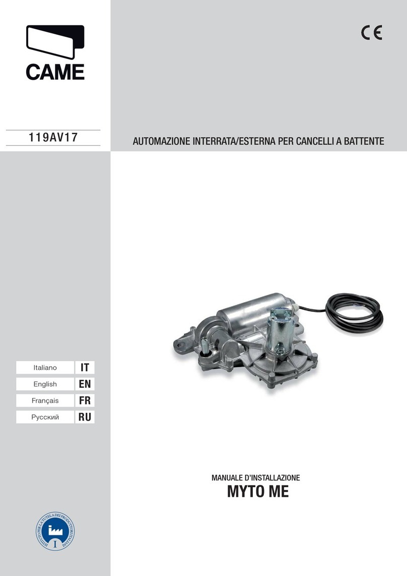
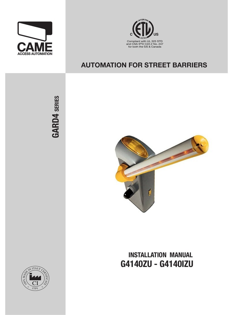
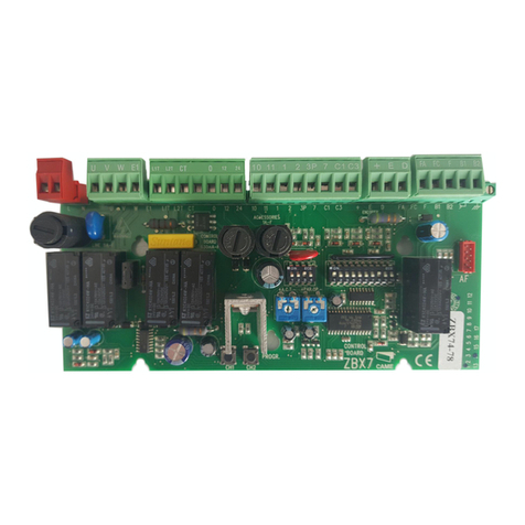
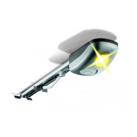
CAME KRONO User manual

CANCELLI AUTOMATICI
Documentazione
Tecnica
S51
rev. 2.1
08/2002
©
CAME
CANCELLI
AUTOMATICI
119DS51
KRONO
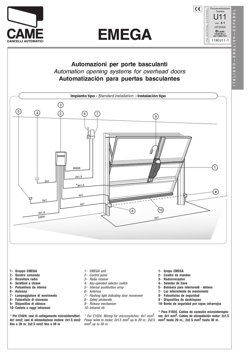
Installation type:
1) Groupe moteur gauche
2) Groupe moteur droit
3) Armoire de commande
4) Récepteur radio
5) Photocellule de
sécurité
6) Sélecteur à clé
7) Clignotant de
mouvement
8) Nantenne de réception
9) Colonne pour
photocellule
10) Emetteur radio
Standard installation
:
1) Left-hand motor unit
2) Right-hand motor unit
3) Control panel
4) Radio reveicer
5) Safety photocell
6) Key-operated selector
switch
7) Flashing light
8) Receiving antenna
9) Photocell column
10) Radio transmitter
Impianto tipo:
1) Gruppo motore sx
2) Gruppo motore dx
3) Quadro comando
4) Ricevitore radio
5) Fotocellula di
sicurezza
6) Selettore a chiave
7) Lampeggiatore di
movimento
8) Antenna di ricezione
9)Colonnina per
fotocel-lula
10) Trasmettitore radio
Instalación tipo:
1) Conjunto motor izq.
2) Conjunto motor der.
3) Cuadro de mandos
4) Radiorreceptor
5) Fotocélula de
seguridad
6) Selèctor con llave
7)
Lámpara
intermitente
8) Antena de recepción
9) Columna para
fotocélula
10)Transmisor
Standard montage:
1) Motoreinheit, links
2) Motoreinheit, rechts
3) Steuergerät
4) Funkempfänger
5) Sicherheits-Photozelle
6) Schlüsselschalter
7) Blinkmeldeleuchte
8) Empfangsantenne
9) Lichtschrankeensäule
10) Handsender
Automazione esterna per cancelli a battente
External automatic opening system for wing gates
Automatisme axtérieur pour portails à battant
Externe Automatik für Flügeltore
Automatizacion exterior para puertas batientes
6
5
4 x 1,5
2 x 1
4 x 1,5
2 x 1,5 T RG 58
3 x 1,5
230 V
&%
!
"
4 x 1 - RX
2 x 1 - TX
4 x 1 - RX
9
9
10
2 x 1 - TX
CAME

2
DESCRIZIONE:
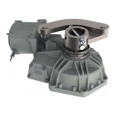
- Automazione esterna per cancelli a battente;
- Progettato e costruito interamente dalla CAME S.p.A., rispon-
de alle vigenti norme di sicurezza in vigore, con grado di pro-
tezione IP 54;
- Garantito 24 mesi salvo manomissioni.
VERSIONI:
KR 300 S
Versione sinistra;
KR 300 D
Versione destra;
KR 310 S
Versione sinistra con finecorsa in apertura e chiusura;
KR 310 D
Versione destra con finecorsa in apertura e chiusura.
DESCRIPTION:
- External automating opening system for wing gates;
- Designed and built entirely by CAME S.p.A., it meets the
regulations in force, with IP54 protection level;
- Guaranteed for 24 months, unless tampered with by
unauthorized personnel.
VERSIONS:
KR 300 S
Left side model ;
KR 300 D
Right side model ;
KR 310 S
- Version left with end-stop during opening and closing;
KR 310 D
- Right version with end-stop during opening and closing;
GENERAL SPECIFICATIONS
ENGLISH
CARATTERISTICHE GENERALI
ITALIANO
KR 510 S
Versione sinistra con finecorsa in apertura e chiusura;
KR 510 D
Versione destra con finecorsa in apertura e chiusura.
LIMITI D'IMPIEGO:
- Dimensione ante fino a 3 metri (KR3), fino a 5 m (KR5);
- Apertura dell’anta: max 120° (KR3), max 130° (KR5);
- I valori indicati (vedi tab. 2 a pag. 4) sono validi per un servi-
zio ad uso residenziale; per un servizio intensivo ridurre tali
valori dal 10 al 20%.
ACCESSORI:
KR001
Serratura a chiave personalizzata.
KR 510 S
- Version left with end-stop during opening and closing;
KR 510 D
- Right version with end-stop during opening and closing;
OPERATIONAL LIMITS:
- Door height up to 3 meters (KR3), to 5 meters (KR5);
- Maximum opening of wing: 120° (KR3),max 130° (KR5);
- The values shown (see table 2 on page 4) refer to normal
residential use; for more intensive use, these values should be
reduced by 10 to 20%.
ACCESSORIES:
KR001
Personalised key lock.
DESCRIPTION:
- Automatisme extérieur pour portails à battant;
- Conçu et construit entièrement par CAME S.p.A., il satisfait
aux normes de sécurité en vigueur avec degré de protection
IP 54;
- Il est garanti 24 mois sauf en cas d’altérations.
VERSIONS:
KR 300 S
Version gauche;
KR 300 D
Version droite;
KR 310 S
Version gauche avec interrupteur de fin de course en ouverture
et fermeture;
KR 310 D
Version droite avec interrupteur de fin de course en ouverture et
fermeture.
CARACTÉRISTIQUES GÉNÉRALÉS
FRANÇAIS
KR 510 S
Version gauche avec interrupteur de fin de course en ouverture
et fermeture;
KR 510 D
Version droite avec interrupteur de fin de course en ouverture et
fermeture.
LIMITES D'EMPLOI:
- Dimensions des portes jusq’a’ 3 mètres (KR3), jusq’a’5 mètres
(KR5);
- L’ouverture standard maximum de la porte est de 120°(KR3),
max 130°(KR5);
- Les valeurs indiquées (voir tableau 2 - pag. 4) sont valables
pour un service à usage résidentielle; pour un service
particuliérement intensif, il convient de réduire ces valeurs de
10 a 20%. ACCESSOIRES:
KR 001
Serrure avec clé personalisée.

3
DESCRIPCIÓN:
- Automatizacion exterior para puertas batientes;
- Completamente diseñado y fabricado por CAME S.p.A.,
responde a las normas de seguridad vigentes, con clase de
protección IP 54;
- Garantizado 24 meses, salvo manipulaciones.
MODELOS:
KR 300 S
Versión izqierda;
KR 300 D
Version derecha;
KR 310 S
Versión izqierda con final de carrera en apertura y cierre;
KR 310 D
Version derecha con final de carrera en apertura y cierre.
BASCHREIBUNG:
- Externe Automatik für Flügeltore;
- Komplett von der CAME S.p.A. geplant und gebaut und den
gültigenSicherheitsvorschriftenentsprechend.SchutzgradIP 54;
- Garantie: 24 Monate, vorbehaltlich unsachgemäßer
Handhabung und Montage.
AUSFÜHRUNGEN:
KR 300 S
Linke Version;
KR 300 D
Rechte Version;
KR 310 S
Linke Version mit Endanschlag beim Öffnen und Schließen;
KR 310 D
Rechte Version mit Endanschlag beim Öffnen und Schließen.
CARACTERÍSTICAS GENERALES
ESPAÑOL
GENERAL SPECIFICATIONS
DEUTSCH
KR 510 S
Linke Version mit Endanschlag beim Öffnen und Schließen;
KR 510 D
Rechte Version mit Endanschlag beim Öffnen und Schließen.
EINSATZBEREICH:
- Torflügeldimensionen bis 3 Meter (KR3), bis 5 Meter (KR5);
- Maximale Standard Toröffnung: 120°(KR3),max 130° (KR5);
- die angegebenen Werte (SieheTabelle 2 auf Seite 4) gelten für
den Einsatz in Wohnanlagen; bei besonders starkem Finsatz
sind diese Werte un 10% bis 20% zu reduzieren.
ZUBEHÖR:
KR 001
Schloß mit personalisiertem Schlüssel.
KR 510 S
Versión izqierda con final de carrera en apertura y cierre;
KR 510 D
Version derecha con final de carrera en apertura y cierre.
LIMITES DE EMPLEO:
- Dimensión hojas hasta 3 metros (KR3), hasta 5 metros (KR5);
- Apertura standard máxima de la hoja: 120° (KR3),max 130°
(KR5);
- Los valores indicados (ver tab. 2 - pag. 4) valen para el uso
residencial; para un servicio más intensivo es preciso reducir
dichos valores de 10 al 20%.
ACCESORIOS:
KR 001
Cerradura con llave personalizada.

4
Tab. 2
LIMITI D'IMPIEGO -
USE LIMITS -
LIMITES D'EMPLOI -
VERWENDUNGSBEREICH -
LIMITES DE EMPLEO
MISURE D'INGOMBRO -
EXTERNAL DIMENSIONS
- MEASURES D'ENCOMBRENT -
ABMESSUNGEN
- DIMENSIONES
3RK
atnaazzehgraL
gniwetagfohtdiW
liatnavudrueugraL
etierblegülfroT
atreupohcnA
atnaoseP
gniwetagfothgieW
liatnavudsdioP
thciweglegülfroT
atreuposeP
00.2m 008gK
05.2m 006gK
00.3m 004gK
5RK
atnaazzehgraL
gniwetagfohtdiW
liatnavudrueugraL
etierblegülfroT
atreupohcnA
atnaoseP
gniwetagfothgieW
liatnavudsdioP
thciweglegülfroT
atreuposeP
00.2m 0001gK
05.2m 008gK
00.3m 006gK
00.4m 005gK
00.5m 004gK
1356 (KR5)
956 (KR3)
194
113
234
304 (KR3)
504 (KR5)
Corsa
Stroke
Course
Lauf
Recorrido
* Ottenuta mediante quadro comando CAME
* Obtained with CAME control panel
* Obtenue au moyen armoire de commande CAME
* Regulierbarer schub erreicht mit Hilfe der CAME Motorsteuerrung
* Empuje regulable obtenido mediante tablero de control CAME
Tab. 1
CARATTERISTICHETECNICHE -
TECNICHAL CARACTERISTICS
- CONTRÔLES GENERALES -
ALLGEMEINE
PRÜFUNGEN
CONTROLES GENERALES
EROTTUDIROTOM IDODARG ENOIZETORP OSEPENOIZATNEMILAOTNEMIBROSSAAZNETOP AZNETTIMRETNI OROVAL ATNIPSASROCOPMET -ROTASNEDNOC E
ROTOMRAEG NOITCETORP GNITAR THGIEW REWOP YLPPUS TNERRUCREWOPELCICYTUDHSUPEMITLEVARTROTICAPAC
RUETCUDÉROTOM EDÉRGED NOITCETORP SDIOPNOITATNEMILANOITPROSBA -CNASSIUP EECNETTIMRETNI LIAVARTED EÉSSUOPESRUOCSPMET -UETASNEDNOC R
ROTOMEBEIRTEG -ARGZTUHCS DTHCIWEG _MORTS GNUGROSREV -MHANFUAMORTS EGNUTSIEL -EUADTLAHCSNIE RRERABLEGERTIEZFUALROTASNEDNOK
ROTCUDERROTOM EDODARG NOICCETORP OSEPNOICATNEMILAAICNEBROSBAAICNETOP AICNETIMRETNI OJABART EJUPME EDOPMEIT ODIRROCER RODASNEDNOC
3RK 45PI gK01 .c.aV032 A1,1 W031 %03
xaM*
N0003 )°09(s22 Fµ8
5RK 45PI gK21 .c.aV032 A1,1 W031 %03 N0003 )°09(s62 Fµ8

5
Tab. 3
MONTAGGIO -
ASSEMBLY
- MONTAGE -
MONTAGE
- MONTAJE
OPIT
EPYT
EPYT
EPYT
OPIT
ARUTREPA
ELGNAGNINEPO
ERUTREVUO
GNUNFFÖ
ARUTREPA
A
mm B
mm C
mm E
mm
3RK °09 031 031 06 019
°021 011 05
5RK °09 002 002 021 0131
°031 002 041 07 0131
Comprobar que:
- la estructura de la
cancela sea robusta y
las bisagras estén
lubricadas;
- la medida C no sea
superior al valore
indicado en la “tab. 3”
pág. 5, en caso
contrario es
necesario reducir el
pilar para alcanzar tal
medida.
Überprüfen:
- Die Torstruktur muß
angemessen robust
und die Angelzapfen
geschmiert sein;
das Maß C darf nicht
über dem in „Tab. 3",
Seite 5 angeführten
Wert liegen, andernfalls
muß zur Erreichung
jenes Maßes auf den
Pfosten eingegriffen
werden.
Controllare che:
- la struttura del cancel-
lo sia adeguatamente
robusta e che i cardini
siano lubrificati;
- la misura C non sia
superiore al valore in-
dicato nella “tab. 3”
pag.5,in caso contra-
rio è necessario inter-
venire sul pilastro in
modo da raggiungere
tale misura.
Make sure:
Vérifier que:
- si la structure du
portail est
suffisamment robuste
et si les gonds sont
lubrifiés;
-la mesure C ne doit
pas être supérieure à
la valeur indiquée
dans le “tableau 3”
page 5. Dans le cas
contraire, il est
nécessaire
d’intervenir sur le
pilier afin d’atteindre
cette mesure.
CONTROLLI GENERALI -
GENERAL CONTROL PROCEDURE -
CONTRÔLES GÉNÉRAUX -
ALLGEMEINE PRÜFUNGEN
CONTROLES GENERALES
Pilastro
Pillar
Pilier
Pfeiler
Pilar
Cerniera /
Hinge /
Charniére /
Scharnier /
Bisagra
Anta
Leaf
Vantail
Tor
Hoja
Battuta d'arresto
Gate stopper
Arrét
Toranschlag
Tope
C
- the structure of the
gate is suitably strong
and the hinges are
lubricated;
- the measure C is not
above the value
indicated in the “tab.
3” pag. 5, otherwise it
is necessary to
intervene on the pillar
so as to reach this
measure.

6
With the gate closed,
install the front bracket
on the gate wing. The
front bracket, when
installed, must be
aligned along the
horizontal axis of the
rear bracket (see figure)
and the distance
between the centre axes
of the brackets must be .
Fixer l’étrier avant sur
le vantail du portail
(vantail en position
fermée), de façon à
obtenir un axe hori-
zontal avec l’étrier
arrière et avec l’entraxe
comme indiqué sur le
schéma.
Bei geschlossenem Tor,
den vorderen Bügel auf
gleicher Achse des
hinteren Bügels und mit
einem Achsabstand
gemäß Abbildung am
Torflügel befestigen.
Estando la puerta
metálica cerrada, fijar
el soporte delantero en
la hoja de la puerta, en
línea horizontal con el
soporte trasero y con
la distancia entre los
ejes indicada.
A cancello chiuso, fis-
sare la staffa di testa
sull’anta del cancello,
in asse orizzontale con
la staffa di coda e
interasse come indica-
to.
2
Livellare le staffe
Levelling the brackets
Mettre les étrier de niveau
Bügel ausrichten
Nivelar los soportes
Staffa di coda
Rear bracket
Etrier arriére
Hinterer Bügel
Soporte trasero
Staffa di testa
Front bracket
Etrier avant
Vorderer Bügel
Soporte delantero
KR3 E = 910
KR5 E = 1310
Den hinteren Bügel
unter Einhaltung der
Maße A und B (Tab. 3)
zwischen Angelzapfen
und der zentralen
Bügelbohrung, die zur
Montage des
Getriebmotors dient,
befestigen.
Der hintere Bügel ist
mit einer Reihe von
Bohrungen versehen,
die die Montage des
Getrie-bemotors
erleichtern sowie eine
Änderung des
Toröffnungswinkels
erlauben. Entsprechend
der
Angelzapfenposition
am Torpfosten kann der
hintere Bügel
verlängert bzw. verkürzt
werden.
Fixér l’étrier arrière en
respectant les cotes A
et B (Tabl. 3) entre le
gond du portail et le
trou central de l’étrier
(sur lequel sera fixé le
motoréducteur).
L’étrier arrière
comprend d’autres
perforations pour
faciliter le montage du
motoréducteur ou
pour modifier l’angle
d’ouverture du portail.
Suivant l’installation
et la position du gond
du portail (par rapport
au pilier), il est
possible d’allonger ou
de raccourcir l’étrier
arrière.
Install the rear bracket
while respecting distan-
ces A and B (Tab. 3)
between the hinge on
the gate and the hole in
the centre of the
bracket (which is used
to hold the gear motor).
The rear bracket is
equipped with
additional holes to
make installation of the
gear motor easier, or to
change the opening
angle of the gate.
The rear bracket can be
lengthened or
shortened to suit the
individual installation
site and the position of
the gate hinge (with
respect to the pillar).
Fissare la staffa di
coda rispettando le
quote A e B (Tab. 3)
tra il cardine del
cancello e il foro
centrale della staffa
(sulla quale deve
essere fissato il
motori-duttore).
La staffa di coda è
dotata di ulteriori
forature per agevolare
il montaggio del
motori-duttore o per
variare l’angolo di
apertura del cancello.
A seconda dell’instal-
lazione e della posi-
zione del cardine del
cancello (rispetto al
pilastro) è possibile
allungare o accorciare
la staffa di coda.
Fijar en soporte
trasero respetando
las medi-das A o B
(Tabla 3) entre el
gozne de la puerta y
el agujero central del
soporte (en que se
debe fijar el
motorreductor).
El soporte trasero
está dotado de otros
agujeros para sim-
plificar el montaje del
motorreductor o para
variar el ángulo de
apertura de la puerta.
En función de la
instalación y de la
posición del gozne de
la puerta metálica
(con relación al pilar)
es posible alargar o
acortar el soporte
trasero.
1
B
A

7
Prevedere una battuta
di arresto meccanico
(ben fissata al suolo) in
chiusura per evitare
l’oltrecorsa anta moto-
riduttore.
Install a mechanical
doorstop (which must be
solidly implanted in the
ground) at the closed
pointsof the gate wing to
prevent the gate wing
from exceeding its
maximum travel at the
open and closed posi-
tions.
Prévoir un dispositif
d’arrêt mécanique
(correctement fixé au
sol) dans la phase de
fermeture afin d’éviter
une course excessive
vantail/motoréducteur.
Einen mechanischen
Endanschlag (gut am
Boden befestigt) in
Öffnungs vorsehen;dies
um Torüberlauf des
Getriebemotors zu
verhindern.
Disponer un tope (bien
fijado en el suelo) para
el cierre para evitar que
la carrera de la hoja
motorreductor sobre-
pase el umbral.
4
Battuta
Doorstop
Dispositif d'arrêt
Anschlag
Tope
Anta
Gate wing
Torflügel
Hoja
Vantail
Battuta (solo per KR300 D/S)
Doorstop (only for KR300 D/S)
Dispositif d'arrêt (uniquement pour KR300 D/S)
Anschlag (Stop) - nur bei KR300 D/S
Tope (sólo para KR300 D/S)
Procedere al montag-
gio del motoriduttore
alle due staffe.
Install the gear motor on
the two brackets.
Réaliser le montage du
motoréducteur sur les
deux étriers.
Getriebemotor auf beide
Bügel montieren.
Montar el motor-
reductor en los dos
soportes.
3
Vite M8 x 35
Screws M8 x 35
Vis M8 x 35
Schrauben M8 x 35
Tornillos M8 x 35
Boccola
Bush
Douille
Buchse
Casquillo Rosetta ø 12
ø 12 Washer
Rondelle ø 12
Unterlegscheibeø12
Arandela ø 12
Dado M8
M8 nut
Ecrou M8
Mutter M8
Tuerca M8
Dado M12
M12 nut
Ecrou M12
Mutter M12
Tuerca M12
Viti ø 3,9 x 9,5
Screws 3,9 x 9,5
Vis 3,9 x 9,5
Schrauben 3,9 x 9,5
Tornillos 3,9 x 9,5

8
- Eseguire i collega-
menti elettrici, come
indicato sull’apposita
etichetta fissata sul
motoriduttore stesso
(Fig. 1);
- per il cavo di collega-
mento utilizzare l’ap-
posito pressacavo
(part. A) in dotazione
fissandolo alla
calottina porta-con-
densatore (part. B).
- Wire the gear motor by
following the wiring
diagram on the label
whichis fastenedtothe
gear motor. (Fig. 1);
- for the cable
connection, use the
appropriate cable
clamp (part. A)
supplied, fixing it to the
capacitorsupport (part.
B).
- Brancher le motoré-
ducteur de la manière
indiquée sur l’étiquet-
te appliquée sur le
motoréducteur (Fig.
1);
- pour le câble de
branchement, utiliser
le serre-câble (pièce
A) fourni de série en
le fixant à la calotte
porte- condensateur
(pièce B).
- Den Getriebemotor
gemäß des Motor-
schildesanschließen
(Abb. 1);
- für das Anschlußkabel
die mitgelieferte kabel-
führung (A) verwenden,
die am Deckel der
Konden-satorhalterung
(B) angebracht wird.
- Conectar el motorre-
ductor como se indi-
ca en la etiqueta
específica incorpora-
da al motorreductor
(Fig. 1);
- para el cable de
conexión use el suje-
tador de cable (det.A)
de serie fijándolo a la
tapa portacondensa-
dor (det. B).
COLLEGAMENTO ELETTRICO -
ELECTRICAL CONNECTONS
- BRANCHEMENTS ÉLECTRIQUES
ELEKTRISCHE ANSCHLÜSSE
- CONEXIONES ELÉCTRICAS
5
Fig 1
Terra
Ground
Terre
Erde
Tierra
UVW
Morsettiera
Terminal block
Borne
Klemmenleiste
Caja de terminales
U/XV/YW
Part. A Part. B

9
Per le regolazioni dei
finecorsa utilizzare un
giravite sull’intaglio
dell’astafilettataAper
l’APERTURA, sul-
l’asta filettata C per la
CHIUSURA.
REGOLAZIONE FINECORSA -
LIMIT SWITCH ADJUSTMENT
- RÉGLAGE INTERRUPTEURS DE FIN DE COURSE
EINSTELLUNG ENDANSCHLAG
- REGULACIÓN DEL FINAL DE CARRERA
C
A
A
C
For the adjustments of
the end stops, use a
screwdriver on the
notch of threaded bar A
for OPENING, on
threaded bar C for
CLOSURE.
Pour régler les inter-
rupteurs de fin de
course, agir avec un
tournevis sur l’entaille
de la tige filetée A
pour l’OUVERTURE et
de la tige filetée C
pour la FERMETURE.
Zur Einstellung vom
Endanschlag ÖFFNEN
den Schraubenzieher
am Schlitz ansetzen,
der sich an der
Gewindestange A
befindet, für den
Endanschlag
SCHLIESSEN am
Schlitz der
Gewindestange C.
Para las regulaciones
de los finales de car-
rera, utilice un
destornillador en la
ranura de la varilla
roscada A para la
APERTURA y en la
ranura de la varilla
roscada C para el
CIERRE.
KR310 D
KR510 D
KR310 S
KR510 S

10
SBLOCCO MOTORIDUTTORE -
GEAR RELEASE
- OPÉRATION DE DÉBLOCAGE -
ANTRIEBSENTRIEGELUNG
DESBLOQUEO MOTORREDUCTOR
- Inserire la chiave (A)
nella serratura ,
ruotar-la per
permettere alla leva
di sblocco (B) di
sganciarsi ed
estrarre la chiave
(fig. 2-3); ruotare
quindi la leva di
sblocco di 90° in uno
dei due sensi (fig. 4).
- Per ribloccare l’anta,
riportare la leva di
sblocco nella
posizione iniziale
(fig. 5).
AB
Fig 2 Fig 3 Fig 4
Fig 5
- Introduire la clé (A)
dans la serrure, tour-
ner pour permettre
au levier de
dèblocage (B) de se
décrocher et extraire
la clé (fig. 2-3);
tourner ensuite le
levier de déblocage
de 90° dans un des
deux sens (fig. 4).
- Introduzca la llave
(A) en la cerradura,
gírela para que la
palanca de
dsbloqueo (B) se de-
senganche y extraiga
la llave (fig. 2-3);
entonces gire la
palanca de desblo-
queo 90° en una des
las dos direcciones
(fig. 4).
- Insert key (A) in the
keylock, turn it to allow
the release lever (B) to
unlock and remove the
key (fig. 2-3); then turn
the release lever 90°
in either direction (fig.
4).
- Den Schlüssel (A) in
das Schloß stecken
und drehen, damit der
Entriegelungshebel
(B) freigegeben wird
und den Schlüssel
abziehen (Abb. 2-3)
Anschließend den
Entriegelungshebel
um 90° in eine der
beiden Richtungen
drehen (Abb. 4).
- Pour bloquer à
nouveau le vantail,
remettre le levier de
déblocage dans sa
position initiale (fig.
5).
- Para volver a
bloquear la hoja,
coloque nuevamente
la palan-ca de
desbloqueo en la
posición inicial (fig.
5).
- To relock the door,
reset the release lever
to the initial position
(fig. 5).
- Um den Torflügel
wieder zu verriegeln,
den Entriegelugshebel
zu-rüch in die Aus-
gangsstellung bringen
(Abb. 5).

11
MANUTENZIONE PERIODICA /
PERIODIC MAINTENANCE /
ENTRETIEN PERIODIQUE /
REGELMÄßIGE WARTUNG
MANTENIMIENTO PERIÓDICO
- Lubrificare la testa
traente e i perni di
rotazione;
- Controllare le viti di
fissaggio;
- Verificare l'integrita'
dei cavi di collegamen-
to.
- Lubricate the drawing
head and the rest pins
- Ceck the clamps screws;
- Ceck the connection
cable's soundness.
- Lubrifier la tête de
traction et les pivots de
rotation;
- Contrôler les vis de
fixation;
- Contrôler l'intégrité
des câbles de
branchement.
-Den Zugkopf und
Drehzapfen schmieren
- Kontrollieren Sie die
Befestigungsschrauben.
- Kontrollieren Sie, ob die
Anschlußkabel unversehrt
sind.
- Lubrique la cabeza
portante y los pernos de
rotación;
- Controle los tornillos
de sujeción;
- Controle el estado de
los cables de conexión.

Tutti i dati sono stati controllati con la
massima cura. Non ci assumiamo co-
munque alcuna responsabilità per
eventuali errori od omissioni.
All data checked with the maximum care.
However,no liabilityisacceptedforanyerror
or omission.
Toutes les données ont été contrôlées
très soigneusement. Nous n’assumons
detoutefaçonaucuneresponsabilitépour
les erreurs ou omissions éventuelles.
Die Daten wurden mit höchster Sorgfalt
geprüft. Für eventuelle Fehler oder
Auslassungen übernehmen wir keine
Haftung.
Todos los datos se han controlado con
lamáxima atención.Noobstante nonos
responsabilizamos de los posibles
errores u omisiones.
CANCELLI AUTOMATICI
CAME LOMBARDIA S.R.L.______COLOGNO M. (MI)
(+39) 02 26708293 (+39) 02 25490288
CAMESUDS.R.L.___________________NAPOLI
(+39) 081 7524455 (+39) 081 7529109
CAME(AMERICA)L.L.C.____________MIAMI(FL)
(+1) 305 5930227 (+1) 305 5939823
CAME AUTOMATISMOSS.A__________MADRID
(+34) 091 5285009 (+34) 091 4685442
CAMEBELGIUM__________________LESSINES
(+32) 068 333014 (+32) 068 338019
CAME FRANCE S.A.____NANTERRE CEDEX (PARIS)
(+33) 01 46130505 (+33) 01 46130500
CAME GMBH________KORNTAL BEI (STUTTGART)
(+49) 07 11839590 (+49) 07 118395925
CAME GMBH____________SEEFELD BEI (BERLIN)
(+49) 03 33988390 (+49) 03 339885508
CAME PL SP.ZO.O______________WARSZAWA
(+48) 022 8365076 (+48) 022 8369920
CAME UNITED KINGDOM LTD___NOTTINGHAM
(+44) 01159 9210430 (+44) 01159 9210431
CAME CANCELLI AUTOMATICI S.P.A.
DOSSON DI CASIER (TREVISO)
(+39) 0422 4940 (+39) 0422 4941
SISTEMA QUALITÀ
CERTIFICATO
ASSISTENZA TECNICA
NUMERO VERDE
800 295830
WEB
www.came.it
E-MAIL
NOTE /
NOTES
/ NOTE /
HINWEIS
/ NOTA
Table of contents
Other CAME Garage Door Opener manuals
Popular Garage Door Opener manuals by other brands

SOMFY
SOMFY Dexxo Pro 800 - 1000 RTS installation manual

Zap
Zap Series 3 Technician's installation and service training manual

Merlin
Merlin MT600 Installation and operating instructions

Automatic Technology Australia
Automatic Technology Australia Securalift GDO 2v4 Installation instructions and owner's manual

Hiland
Hiland SL16 Series user manual

Nice
Nice ROBUS RB400 Instructions and warnings for the fitter