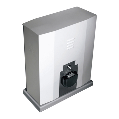
CAME ZBX7 User manual

Documentazione
Tecnica
S19
rev. 2.1
11/2005
©
CAME
CANCELLI
AUTOMATICI
ZBX7
SERIE Z |
Z SERIES
/
SERIE Z
SCHEDA COMANDO
CONTROL BOARD
TARJETA DE MANDO
ITALIANO/
ENGLISH
/ESPAÑOL
319S19-1
ITALIANO—ENGLISH—ESPAÑOL
CARACTERISTICAS GENERALES
Descripciön cuadro de mando
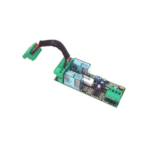
La tarjeta de mando ZBX7 es idónea
para el accionamiento de automati-
zaciones de puertas correderas ali-
mentadas a 230V monofásica de la
serie BX-A/BX-B.
La tarjeta se introduce y fija en la caja
respectiva en el motorreductor (véa-
se descripción montaje en pág.12), y
se alimenta con una tensión de 230V
(c.a.) en los bornes L1 y L2.
La tarjeta está protegida en la entrada
por dos fusibles de 5A, mientras que
los dispositivos de accionamiento de
baja tensión (24V) están protegidos
por fusible de 1A.
La potencia total de los accesorios
(24V) no tiene que superar los 20W.
GENERAL CHARACTERISTICS
Description of control panel
The ZBX7 control board is used as a
remote control for BX-A/BX-B series
230V single-phase automated sliding
gates.
The board is introduced and fixed in
place in the gearmotor's circuit board
holder (see assembly description on
page 12), at 230V (a.c.) in terminals
L1 and L2.
The inlet is protected with two 5A fuses,
while the low voltage (24V) control de-
vices are protected with a 1A fuse.
The accessorie's total capacity (24V)
should not exceed 20W.
CARATTERISTICHE GENERALI
Descrizione scheda
La scheda comando ZBX7 è adatta al
comando di automazioni scorrevoli
alimentati a 230V monofase della se-
rie BX-A/BX-B.
La scheda va inserita e fissata nel
contenitore porta-schede del motori-
duttore (vedi descrizione montaggio
a pag.12), ed alimentata con una ten-
sione di 230V(a.c.) nei morsetti
L1 e L2.
É protetta in ingresso con due fusibi-
li da 5A, mentre i dispositivi di co-
mando a bassa tensione (24V) sono
protetti con fusibile da 1A.
La potenza complessiva degli acces-
sori (24V) non deve superare i 20W.
ENGLISH
ESPANOL
ITALIANO

-2-
ITALIANO—ENGLISH—ESPAÑOL
Sicurezza
Le fotocellule possono essere col-
legate e predisposte per:
-
Riapertura
in fase di chiusura (2-
C1), le fotocellule rilevando un osta-
colo durante la fase di chiusura del
cancello, provocano l'inversione di
marcia fino alla completa apertura;
-
Stop parziale,
arresto del cancello
se in movimento con conseguente
pre disposizione alla chiusura auto-
matica (2-C3);
-
Stop totale
(1-2), arresto del cancel-
lo con l'esclusione del ciclo di chiu-
sura automatica, per riprendere il
movimento del cancello, agire sulla
pulsantiera o sul radiocomando;
Nota: Se un contatto di sicurezza
normalmente chiuso (2-C1, 2-C3, 1-
2) si apre, viene segnalato dal
lampeggio del LED di segnalazio-
ne (pag.14 - n°10);
-Rilevazione di presenza ostacolo.
A motore fermo (cancello chiuso,
aperto o dopo un comando di stop
totale), impedisce qualsiasi movi-
mento se i dispositivi di sicurezza
(es. fotocellule) rilevano un ostaco-
lo;
Accessori collegabili
-
Lettore ottico art.001B4336
, rileva
gli ostacoli durante i movimenti del
cancello, nella fase di apertura il
cancello si ferma e riprende il movi-
mento di chiusura dopo il conteggio
della chiusura automatica, mentre
in chiusura inverte il senso di mar-
cia.
Attenzione! Nella fase di chiusura,
dopo tre rilevamenti consecutivi, il
cancello si fer ma in apertura e viene
esclusa la chiusura automatica, per
riprendere il movimento del cancel-
lo, agire sulla pulsantiera o sul
radiocomando;
Safety
Photocells can be connected to ob-
tain:
-Re-opening during closure (2-C1), if
the photocells identify an obstacle while
the gate is closing, they will reverse
the direction of movement until the gate
is completely open;
-Partial stop, shutdown of moving gate,
with activation of an automatic closing
cycle (2-C3);
-Total stop (1-2), shutdown of gate
movement without automatic closing;
a pushbutton or radio remote control
must be actuated to resume move-
ment).
N.B: If an NC safety contact (2-C1, 2-
C3, 1-2) is opened, the LED
(pag.14 -n°10) will flash to indicate this
fact;
-Obstaclepresencedetection.Whenthe
motor is stopped (gate is closed, open
or half-open after an em ercency stop
command), the transmitter and the con-
trol pushbutton will be deactiv ated if an
obstacle is detected by one of the
safety devices (for example, the photo-
cells);
Accessories which can be
connected to this unit
-Item. 001B4336 optical reader, de-
tects obstacles during the gate's
movement; during the opening phase,
the gate stops and then begins a clos-
ing movement after the automatic
closure count, whilst during closure the
direction of movement is inverted.
Warning: during closure, if obstacles
are detected three times consecutive-
ly, the gate will remain open and
automatic closure will be discontinued.
To resume the gate's movement, use
the push-button panel or the remote
control;
Seguridad
Il est possible de brancher des pho-
tocellulesetdelesprogrammerpour:
-
Réouverture
en phase de fermeture
(2-C1), les cellules photoélectriques
provoquent l'inversion de marche
jusqu'à l'ouverture complète si elles
relèvent un obstacle durant la phase
de fermeture du portail;
-
Parada parcial,
parada de la puerta
si se encuentra en movimiento con
la consiguiente predisposición al
cierre automático (2-C3);
-
Parada total
(1-2), parada de la puer-
ta excluyendo el posible ciclo de cie-
rre automático, para reactivar el mo-
vimiento es preciso actuar en el te-
clado o en el mando a distancia;
Nota
: La apertura de un contacto de
seguridad normalmente cerrado (2-
C1, 2-C3, 1-2) es señalada por medio
del destello LED de señalización
(pàg. 14 - n° 10).
-Detección de presencia obstàculo.
Con el motor parado (puerta cerra-
da, abierta o en posición semi-abierta
obtenida a través de un comando de
stop total), anula cualquier función
del transmisor o del botòn en caso
de obstàculo detectado por los dis-
positivos de seguridad (por ejem-
plo: fotocélulas).
Accesorios conectables
-
Lector óptico art. 001B4336
, detecta
losobstáculosdurantelosmovimien-
tos de la puerta; durante la apertura
la puerta se detiene e inicia el movi-
mientodecierre,despuésdelacuenta
del cierre automático; mientras, que
durante el cierre, invierte la direc-
ción del movimiento.
Atención: durante el cierre, tras tres
detecciones consecutivas, la puerta
se detiene en el movimiento de aper-
tura y se desconecta el cierre
automático, para reactivar el movi-
miento de la puerta, use el pulsador
o el radiocontrol;

-3-
ITALIANO—ENGLISH—ESPAÑOL
-Cycle lamp. The lamp which lights the
manoeuvring zone: it remains lit from
the moment the doors begin to open
until they are completely closed (in-
cluding the time required for the
automatic closure). In case automatic
closure is not enabled, the lamp re-
mains lit only during movement.
The function of the cycle lamp is ob-
tained in output W-E1 only if dip switch
numbers: 1 “automatic closing” and No.
6 “detect obstacle presence” are set to
ON (see page 16).
Otherfunctions
-
Automaticclosing.
The
automaticclos-
ing timer is automatically activated at
the end of the opening cycle. The pre-
set, adjustable automatic closing time
is automatically interrupted by the acti-
vation of any safety system, and is
deactivated after a STOP command or
in case of power failure;
-Partial opening.Gate opening for pas-
sage on foot is activated by connect-
ing to the 2-3P terminal blocks and it
can be adjusted by the AP.PARZ. trim-
mer. By using this function, automatic
closure varies as follows:
1) Dip 1 ON - Automatic closure acti-
vated.
-after a partial opening, the closure time
does depend on any adjustment of the
TCA trimmer.
2) Dip 1 OFF - Automatic closure de-
activated.
- If the TCA trimmer is set to the min-
imum, after a partial opening, auto-
matic closure counting does not begin;
- If the TCA trimmer is set to the max-
imum, after a partial opening, closing
time is set to 8 seconds.
-"Operator present". Gate operates
only when the pushbutton is held down
(the radio remote control system is
deactivated);
-Slowing at the limit switch.
FUNCTION AVAIABLE ONLY FOR GATES WEIGH-
ING UP TO 300 KG, OTHERWISE IT MUST BE
DISACTIVATED
-Lámpara ciclo. Lámpara que alum-
bra la zona de maniobra: se queda
encendida a partir del momento en
que las hojas empiezan la apertura
hasta el cierre completo (incluyendo
el tiempo de cierre automático). Si
no se habilita el cierre automático, el
cierre permanece encendido sólo du-
rante el movimiento.
El funcionamiento de la lámpara ci-
clo se obtiene en la salida W-E1 sólo
si los dips n°1 “cierre automático” y
n°6 “detección presencia obstáculo”
están colocados en ON, véase
página 16.
Otras funciones
-
Cierre automático
. El temporizador
de cierre automático se autoalimen-
ta en fin-de-tiempo carrera en fase
de apertura. El tiempo prefijado re-
gulable, sin embargo, está subordi-
nado a la intervención de posibles
accesorios de seguridad y se exclu-
ye después de una intervención de
parada o en caso de falta de energía
eléctrica;
-
Apertura parcial
. La apertura de la
verja para el paso peatonal, se acti-
va conectado los bprnes 2-3P y pue-
de ser regulada por medio del trim-
mer AP.PARZ.;
Con esta función, el cierre automá-
tico se modifica de la siguiente ma-
nera:
1) Dip 1 en ON «cierre automático
activo».
- Tras una apertura parcial, el tiem-
po de cierre es dependiente de la re-
gulación del trimmer TCA.
2) Dip 1 en OFF «cierre automático
desactivado».
-Si el trimmer del TCA está regula-
do al mínimo, tras una apertura par-
cial no se acciona la cuenta de cie-
rre automático;
- Si el trimmer del TCA está regula-
do al máximo, tras una apertura par-
cial, el tiempo de cierre queda fijo
en 8".
-
Función a "hombre presente"
. Fun-
cionamiento de la puerta mantenien-
do pulsada la tecla (excluye la fun-
ción del mando a distancia);
-Desaceleraciòn en final de carrera.
FUNCIÓN DISPONIBLE SÓLO PARA
CANCELAS CON 300 KG DE PESO MÁXIMO,
EN CASO CONTRARIO DEBE SER
DESACTIVADA
-
Lampada ciclo
. Lampada che illu-
mina la zona di manovra, rimane
accesa dal momento in cui le ante
iniziano l ’apertura fino alla comple-
ta chiusura (compre so il tempo di
chiusura automatica). Nel caso non
viene inserita la chiusura automati-
ca, rimane accesa solo durante il
movimento. La funzione della lam-
pada ciclo se i dip n°1 “chiusura
automati ca” e n°6 “rilevazione pre-
senza ostacolo” sono posizioni in
ON, vedi pagina 16.
Altre funzioni
-
Chiusura automatica.
Il temporiz-
zatore di chiusura automatica si au-
toalimenta a finecorsa in apertura. Il
tempoprefissatoregolabile, è in ogni
modo subordinato dall'intervento di
eventuali accessori di sicurezza e si
esclude dopo un intervento di "stop"
o in mancanza d'energia elettrica.
-
Apertura parziale
. Apertura del can-
cello per passaggio pedonale, viene
attivata collegandosi ai morsetti 2-
3P ed è regolabile mediante trimmer
AP.PARZ.. Con questa funzione, la
chiusura automatica varia nel se-
guente modo:
1) Dip 1 in ON «chiusura automatica
attivata».
- Dopo un'apertura parziale, il tem-
po di chiusura è dipendente dalla
regolazione del trimmer TCA.
2) Dip 1 in OFF «chiusura automati-
ca disattivata».
- Se il trimmer del TCA è regolato al
minimo, dopo un'apertura parziale
non parte il conteggio di chiusura
automatica.;
- Se il trimmer del TCA è regolato al
massimo, dopo un 'apertura parzia-
le, il tempo di chiusura è fisso a 8
secondi.
-
"Uomo presente"
. Funzionamento
del cancello mantenendo premuto il
pulsante (esclude la funzione del
radiocomando);
-
Rallentamento a finecorsa.
FUNZIONE DISPONIBILE SOLO PER CANCELLI
CON PESO MASSIMO DI 300 KG, ALTRIMENTI
DEVE ESSERE DISATTIVATA

-4-
ITALIANO—ENGLISH—ESPAÑOL
The gate slow down before the opening
or closing movement is completed.
Only works with the optical reader on.
After every opening and closing of the
safety door or after restoring the volt-
age, the slowing function is active from
the 2nd command onwards.
-Pre-flashing. After an opening or clos-
ing command, the flasher connected to
the W-E1 flashes for 5 seconds before
beginning the procedure;
-Closing command. Function of clos-
ing the gate only, with a wire less
control device connected to contact
2-7, set dip 1 to ON (4- way module),
see page 22;
-Opening command. Function of open-
ing the gate only, with a wireless control
device connect ed to contact 2-3P, set
dip2toON(4-waymodule),seepage22;
-Type of command:
-Open-stop-close-stop by button and
transmitter;
-Open-close by button and transmitter;
-Open only by transmitter.
Adjiustments
- Automatic closure time;
- Partial opening time.
ATTENZIONE: prima di interveni-
re all'interno dell'apparecchiatu-
ra, togliere la tensione di linea
IMPORTANT: Shut off the mains
power before servicing the inside
of the unit.
ATENCION: antes de actuar den-
tro del aparado, quitar la ten-
sión de línea
Il cancello rallenta la corsa prima
della completa apertura o chiusura.
Funziona solo con lettore ottico in-
serito.
Dopo ogni chiusura e apertura dello
sportellino di sicurezza o dopo un
ripristino della tensione, la funzione
di rallentamento è attiva dal 2° co-
mando in poi.
-
Prelampeggio
. Dopo un co mando
di apertura o di chiu sura, il lampeg-
giatore collegato su W-E1, lampeg-
gia per 5 secondi prima di iniziare la
manovra.
-Comando di chiusura.
Funzione di
sola chiusura del can cello, con di-
spositivo di co mando collegato sul
contatto 2-7, posizionare il dip 1 in
ON (modulo a 4 vie), vedi pagina 22;
-Comando di apertura.
Funzione di
sola apertura del cancello, con di-
spositivo collegato sul contatto 2-
3P, posizionare il dip 2 in ON (modu-
lo a 4 vie), vedi pagina 22;
-Tipo di comando
:
-apre-stop-chiude-stop con pulsan-
te e/o trasmettitore;
-apre-chiude con pulsante e/o tra-
smettitore;
-solo apre per trasmettitore.
Regolazioni
- Tempo chiusura automatica;
- Tempo di apertura parziale.
La puerta desacelera la carrera antes
de completar la apertura o el cierre.
Funciona sólo con lector óptico co-
nectado.
Tras cada apertura o cierre de la tapa
de seguridad, o tras una reactiva-
ción de la tensión, la función de
desaceleración está activa desde el
2° mando en adelante.
-
Intermitencia
. Después de un man-
do de apertura o cierre, la lámpara
intermitente conectada en W-E1, par-
padea por 5 segundos antes de co-
menzar la maniobra;
-Mando de cierre.
Función sólo de
cierre de la puerta, con dispositivo
de mando conectado en el contacto
2-7, coloque el dip 1 en ON (módulo
de 4 vías), véase página 22;
-Mando de apertura.
Función sólo
de apertura de la puerta, con dispo-
sitivo de mando conectado en el
contacto 2-3P, coloque el dip 2 en
ON (módulo de 4 vías), véase página
22;
-Tipo de mando
:
-abrir-stop-cerrar-stop para botón y
transmisor;
-abrir-cerrar para botón y transmi-
sor;
-sólo apertura para transmisor.
Regulaciones
- Tiempo de cierre automático;
- Tiempo de apertura parcial.

-5-
ITALIANO—ENGLISH—ESPAÑOL
12
3
5
4
DESCRIZIONE DI MONTAGGIO -
ASSEMBLY DESCRIPTION
-DESCRIPTIÓN DEL MONTAJE
-Abra la puerta de acceso al desblo-
queo, afloje el tornillo de la tapa del
cuadro de mando y quítelo (1).
-Quite el cubretarjeta de la placa de
soporte del cuadro de mando (2).
-Enganche y fije la tarjeta ZBX7 a la
placa de soporte del cuadro de man-
do, con los tornillos suministrados
(3).
-Vuelva a colocar el soporte cubreta-
ryeta (4).
-Realice la conexión eléctrica, fije la
tapa del cuadro de mando y cierre la
puerta de acceso al desbloqueo (5).
-Aprire lo sportello accesso sblocco,
allentare la vite del coperchio quadro
comando e levarlo (1).
-Rimuovere il copri-scheda dalla pia-
stra di supporto quadro comando
(2).
-Agganciare e fissare la scheda ZBX7
nella piastra di supporto quadro co-
mando con le viti predisposte (3).
-Riposizionare il supporto copri-
schede (4).
-Procedere al collegamento elettri-
co, fissare il coperchio del quadro
comando e chiudere lo sportello ac-
cesso blocco (5).
-Open the release access door, loosen
the screws of the control panel cover
and lift it (1).
-Remove the circuit board cover from
the control panel support plate (2).
-Hook and fix the ZBX7 board to the
control panel support plate with the
appropriate screws (3).
-Reposition the circuit board cover sup-
port (4).
-Proceed with the electric connection,
replace the control panel cover and
close the release access door (5).

-6-
ITALIANO—ENGLISH—ESPAÑOL
11
11
1
1010
1010
10
1111
1111
11
33
33
3
22
22
2
44
44
4
55
55
5
66
66
6
77
77
7
88
88
899
99
9
SCHEDA BASE -
MOTHERBOARD
- TARJETA BASE
COMPONENTI PRINCIPALI
1 Morsettiere di collegamento
2 Fusibili di linea 5A
3 Fusibile accessori 1A
4 Fusibile scheda 630 mA
5 Pulsanti di memorizzazione co-
dice radio
6 Trimmer di regolazione apertura
parziale
7 Trimmer di regolazione tempo di
chiusura automatica
8 Selettore funzioni a 4 dip (vedi
pag.22)
9 Selettore funzioni a 10 dip (vedi
pag.19)
10 Innesto scheda radiofrequenza
(vedi tabella)
11 LED segnalazione
MAIN COMPONENTES
1
Terminal block for external conec-
tions
2 Line fuse, 5A
3 Fuse on accessory power line, 1A
4 Fuse Control Board 630 mA
5Radio-code save buttons
6 Trimmer for adjustment operating
time
7Trimmer for adjustment automatic
closing
84-dip function switch (see pag.22)
910-dip function switch (see pag.19)
10SocketAFradiofrequencyboard(see
table)
11Signal LED
PRINCIPALES COMPONENTES
1 Caja de bornes para las conexió-
nes
2 Fusible de línea 5A
3 Fusible accesorios 1A
4 Fusible ficha de control 630 mA
5 Teclas de memorización del códi-
go radio
6 Trimmer de regulación tiempo tra-
bajo
7 Trimmer deregulación tiempo cie-
rre automático
8 Selector de funciones con 4 dip
(vedas pág.22)
9 Selector de funciones con 10 dip
(vedas pág.19)
10Conexión tarjeta radiofrecuencia
AF (vedas tabla)
11LED de señal

-7-
ITALIANO—ENGLISH—ESPAÑOL
Per variare la coppia motrice, spo-
stare il faston indicato (con filo di
colore nero) su una delle 4 posizioni;
1 min. - 4 max
To vary the motor torque, move the
indicated faston to one of the four posi-
tions: 1=min, 4=max
Para variar el par motor, desplazar el
faston indicado hasta una de las 4
posiciones; 1 mín. - 4 máx.
LIMITATORE DI COPPIA MOTORE /
MOTOR TORQUE LIMITER
/LIMITADOR DE PAR MOTOR

-8-
ITALIANO—ENGLISH—ESPAÑOL
10 11 1 2 7 C1L1 L2 UVWE1 3P C3 FA FC F B1 B2
ED
UVWE1
UVWE1
2
1345678910
ON
L1L1
L1L1
L1
L2L2
L2L2
L2
UU
UU
U
WW
WW
W
VV
VV
V
WW
WW
W
E1E1
E1E1
E1
11
11
1
22
22
2
22
22
2
3P3P
3P3P
3P
1010
1010
10
1111
1111
11
22
22
2
77
77
7
Alimentazione230V(a.c.)
230V(a.c.)powerinput
Alimentación230V(a.c.)
Motore monofase230V (a.c.)
230V(a.c.)single-phasemotor
Motor monofásico 230V (a.c.)
Uscita 230V (a.c.) in movimento
(es.lampeggiatore-max.25W)
230V (a.c.) output in motion
(e.g. flashing light - max. 25W)
Salida de 230V (a.c.) en movimento
(p.ej. lámpara intermitente - max. 25W)
Uscita 230V (a.c.) lampada ciclo - max. 60W
230V (a.c.) max.60W - cycle lamp
Salida de 230V (a.c.) lámpara ciclo - max.60W
COLLEGAMENTI ELETTRICI -
ELECTRICAL CONNECTIONS -
CONEXIONES ELÉCTRICAS
Alimentazioneaccessori24V (a.c.) max.20W
24V(a.c.)Poweringaccessories(max20W)
Alimentaciónaccesoios24V(a.c.)max.20W
Pulsantestop(N.C.)
Pushbuttonstop(N.C.)
Pulsadorde stop(N.C.)
Pulsanteperaperturaparziale(N.O.)
Button(N.O.)forpartialopening
Pulsador (N.O.)para aperturaparcial
Contattoradio e/opulsante percomando (vedidippag.19-22)
Contactradioand/orbuttonforcontrol(seedippag.19-22)
Contactoradioy/o pulsadorpara mando(vedas dippág.19-22)

-9-
ITALIANO—ENGLISH—ESPAÑOL
1111
1111
11
FCFC
FCFC
FC
1111
1111
11
FAFA
FAFA
FA
22
22
2
C1C1
C1C1
C1
FF
FF
F
FAFA
FAFA
FA
FF
FF
F
FCFC
FCFC
FC
22
22
2
C3C3
C3C3
C3
B1B1
B1B1
B1
B2B2
B2B2
B2
Lampadaspia(24V-3Wmax.)"cancelloaperto"
(24V-3Wmax.)"gate-opened"signallamp
Lámparaindicadora(24V-3Wmax.)"puertaabierta"
Lampadaspia(24V-3Wmax.)"cancellochiuso"
(24V-3Wmax.)"gate-closed"signallamp
Lámparaindicadora(24V-3Wmax.)"puertacierre"
Contatto(N.C.)di«riaperturadurantelachiusura»
Contact(N.C.)for«re-openingduringtheclosing»
Contacto(N.C.) para la«aperturaen lafase decierre»
Contatto(N.C.)di«stopparziale»
Contact(N.C.) for«partial stop»
Contacto(N.C.)parala«paradaparcial»
Uscitacontatto (N.O.)Portatacontatto:5A-24Vd.c.
Contact output (N.O.) Resistive load: 5A -
24V d.c.
Salidacontacto (N.O.)Carga resistiva:5A -24V d.c.
Collegamentofinecorsaapre
Connection limit switch opens
Conexiónfindecarreraapertura
Collegamentofinecorsachiude
Connection limit switch closes
Conexiónfindecarrera cierre
Collegamentoantenna
Antennaconnection
Conexiónantena

-10-
ITALIANO—ENGLISH—ESPAÑOL
ONON
ONON
ON
OFFOFF
OFFOFF
OFF
2
1345678910
ON
SELEZIONI FUNZIONI -
SELECTION OF FUNCTIONS
- SELECCIÓN DE LAS FUNCIONES
DIP-SWITCH 10 VIE
/ 10-WAY DIP-SWITCH
/
DIP-SWITCH 10 VÍAS
1 ON Cierre automático activado;
(1 OFF-desactivado)
2 ON "Abrir-stop-cerrar-stop" con
botón(2-7)yradiocontrol(tar-
jeta AF conectada) activado;
2 OFF "Abrir-cerrar" con botón (2-7)
y radiocontrol (tarjeta AF co-
nectada) activado;
3 ON "Soloapertura"conradiocon-
trol (tarjeta AF conectada)
activado; ( 3 OFF desactiva-
do)
4 OFF "Hombre presente" (escluye
la función del mando de ra-
dio) desactivado; (4ON -
activado)
5 ON Pre-intermitencia activado
( 5 OFF- desactivado)
6 ON Detección del presencia obs-
táculo activado; (6 OFF -
desactivado)
7 OFF Reapertura en la fase de cie-
rre activado; conecte el
dispositivo de seguridad a
los bornes 2-C1, (si no se
utiliza, poner el dip en ON)
8 OFF Parada parcial activado; co-
necte el dispositivo de
seguridada los bornes 2-C3,
(si no se utiliza, poner el dip
en ON)
9 OFF Parada total activado; conec-
te el dispositivo de seguridad
a los bornes 1-2, (si no se
utiliza, poner el dip en ON)
10 OFF Desaceleración con final de
carrera activado (sólo para
cancelas de hasta 300 Kg);
con lector óptico conectado
(10 ON-desactivado)
NOTA: las selecciones se realizan
con el motor parado en posición de
cierre.
1 ON Automatic closure activated;
(1 OFF-deactivated)
2 ON "Open-stop-close-stop" with
button (2-7) and radio control
(AF board inserted) activated;
2 OFF "Open-close" with button (2-7)
and radio control (AF board in-
serted) activated;
3 ON "Only opening" with radio con-
trol (AF board inserted)
activated;
(3 OFF-deactivated)
4 OFF "Operatorpresent"operation(ra-
dioremotecontrolisdeactivated
when function is selected) de-
activated;
(4 ON -activated)
5 ON Pre-flashing activated; (5 OFF-
deactivated)
6 ON Obstacle detection device acti-
vated;
(6 OFF-deactivated)
7 OFF Re-openinginclosingphaseac-
tivated; connect the safety
device on terminals 2-C1, (if not
used, set the dip-switch to ON)
8 OFF Partial stop activated; connect
the safety device on terminals
2-C3, (if not used, set the dip-
switch to ON)
9 OFF Total stop activated; connect
the safety device on terminals
1-2, (if not used, set the dip-
switch to ON)
10 OFFLimit switch slowing activated
(only for gates weighing up to
300 kg); connect the optical
reader.
(10 ON-deactivated)
NOTE: theselectionsshouldbecarried
out with the motor off in the closed
position.
1 ON Chiusura automatica attiva-
ta; (1 OFF - disattivata)
2 ON "Apre-stop-chiude-stop" con
pulsante (2- 7) e radio-
comando(schedaAFinserita)
attivata;
2 OFF "Apre-chiude" con pulsante
(2-7) e radiocomando (sche-
da AF inserita) attivata;
3 ON "Sola apertura" con radio co-
mando (scheda AF inserita)
attivata;
(3 OFF - disattivata)
4 OFF "Uomo presente"(esclude il
funzionamento del radio co-
mando) disattivata;
(4ON - attivata)
5 ON Prelampeggio attivato;
(5OFF-disattivato)
6 ON Rilevazione di presenza osta-
coloattivata;(6OFF-disttivata
7 OFF Riapertura in fasedi chiu sura
attivata; con dispositivo di si-
curezza collegato ai morsetti
2-C1, (se non viene utilizzato
il dispositivo, selezionare il
dip in ON).
8 OFF Stop parziale attivata; con
dispositivo di sicurezza col-
legato ai morsetti 2-C3, (se
non viene utilizzato il dispo-
sitivo, selezionare il dip
in ON)
9 OFF Stop totale attivata con di-
spositivo di sicurezza
collegato ai morsetti 1-2, (se
non viene utilizzato il dispo-
sitivo, selezionare il dip in
ON)
10 OFF Rallentamenti a fine corsa
attivati (solo per cancelli fino
a 300 Kg); con lettore ottico
installato
(10 ON- disattivati)
NOTA: le selezioni vanno eseguite a
motore fermo in posizione di
chiusura.

-11-
ITALIANO—ENGLISH—ESPAÑOL
A P . P A R Z .
T . C . A .
REGULACIÓN TRIMMERS
EINTELLUNG TRIMMERS
RÉGLAGE TRIMMERS
TRIMMERS ADJUSTMENT
REGOLAZIONE TRIMMERS
ONON
ONON
ON
OFFOFF
OFFOFF
OFF
"!
DIP-SWITCH 4 VIE
/ 4-WAY DIP-SWITCH
/ DIP-SWITCH 4 VÍAS
1ON
"Closing only" with a wire less
control device con nected to the
2-7 contact activated;
1 OFF" Open-close" with a wire less
control device con nected to the
2-7contact(see the10-way func-
tion selector dip 2) activated;
2 ON "Opening only" with a wireless
control device connected to the
2-3P contact activated;
2 OFFPartial opening activated;
3 OFFOptical reader activated; item.
001B4336 connected (3ON - de-
sactivated);
4 ON Not connected
NOTE: the selections should be carried
out with the motor off in the closed
position.
1 ON "Sólo cierre" con dis po siti-
vo de mando conecta do en el
con tacto 2-7 activo;
1 OFF "Abrir-cerrar" con dispo siti-
vo de mando conectado en
2-7 (véase dip 2 del selec tor
de funciones de 10 vías) acti-
vo;
2 ON "Sólo apertura" con disposi-
tivo de mando cone- ctado en
el contacto 2-3P activo;
2 OFF Apertura parcial activo;
3 OFF Lector óptico activo; art.
001B4336 conectado (3ON -
desactivado);
4 ON No conectado
NOTA: las selecciones se realizan
con el motor parado en posi-
ción de cierre.
1 ON "Sola chiusura" con dispositi-
vo di comando collegato sul
contatto 2-7 attivata;
1 OFF"Apre-chiude"condispositivo
di comando collegato su 2-7
(vedi dip 2 del selet tore fun-
zioni a 10 vie) attivata;
2 ON "Sola apertura" con dispositi-
vo di comando collegato sul
contatto 2-3P attivata;
2 OFFApertura parziale attivata;
3 OFFLettore ottico attivato; art.
001B4336 installato (3ON - di-
sattivato);
4 ON Non connesso
NOTA: le selezioni vanno eseguite a
motore fermo in posizione di chiu-
sura.
TrimmerT.C.A.=Regulacióndeltiempo
de cierre automático, desde un mínimo
de 0 segundos hasta un máximo de 120
segundos.
TrimmerAP.PARZ.=Regulacióndeaper-
tura parcial, desde un mínimo de 0 se-
gundos hasta un máximo de 16 segun-
dos.
Trimmer T.C.A. = Regolazione tempo di
chiusura automatica da un minimo di 0
secondi a un massimo di 120 secondi.
TrimmerAP.PARZ.=Regolazionediaper-
tura parziale da un minimo di 0 secondi
a un massimo di 16 secondi.
Trimmer T.C.A. = Adjusts automatic clos-
ing time from a minimum of 0 seconds to a
maximum of 120 seconds.
TrimmerAP.PARZ.=Adjustspartialopen-
ing from a minimum of 0 seconds to a
maximum of 16 seconds.
DIP-SWITCH 4 VIE
/ 4-WAY DIP-SWITCH
/
DIP-SWITCH 4 VÍAS
REGOLAZIONE TRIMMERS
TRIMMERS ADJUSTMENT
REGULACIÓNTRIMMERS

-12-
ITALIANO—ENGLISH—ESPAÑOL
COLLEGAMENTOPER2MOTORIABBINATI
CONNECTIONSFOR2COMBINEDMOTORS
CONEXIÓNPARA2MOTORESACOPLADOS
Nel caso d'installazione di due moto-
ri abbinati, procedere nel seguente
modo:
- Coordinare il senso di marcia dei
motoriduttori "A" e "B", modificando
la rotazione del motore "B" (vedi
collegamento finecorsa);
- Assicurarsi che sia inserito il ricevi-
tore radio (AF) sul quadro del motore
"A" (1);
- Su entrambi i quadri devono essere
fatte le stesse regolazioni e
funzioni (2);
- Eseguire i collegamenti elettrici tra
le morsettiere del quadro "A" e "B"
come da «Fig. A»;
- Ilpulsantediaperturaparziale(2-3P)
va collegato sulla morsettiera del
quadro del motore interessato;
N.B. Per comandare le automazioni
con l'utilizzo del radiocomando oc-
corre, memorizzare il codice del tra-
smettitore sul canale CH2 della sche-
da base del motore "A" (vedi pro-
grammazione radiocomando).
Dopo aver memorizzato il codice,
collegare i contatti B1-B2 con 2-7. Il
comando di apertura sarà di tipo
«apre-chiude», «apre-stop-chiude-
stop» o «solo apertura», secondo la
disposizione dei dip 2-3, selezionati
su entrambe le schede.
In case two combined motors are in-
stalled, proceed in the following man-
ner:
- Coordinate the direction of the "A" and
"B" gearmotors, modifying the rotation
of motor "B" (see limitswitch setting);
- Make sure that the (AF) radio receiv-
er is connected to the motor "A" con-
trol panel (1);
- The same settings and functions must
be made on both control panels (2).
- Make the necessary electric connec-
tions between the terminal boards of
the "A" and "B" panels as in «Fig. A»;
- The partial aperture button (2-3P)
should be connected to the terminal
board of the corresponding motor con-
trol panel;
N.B. To control the automatic gate with
the wireless control, it is first necessary
to memorise the transmitter code on
channel CH2 of the motor "A" mother-
board (see programming remote con-
trol). After memorising the code, con-
nect contacts B1-B2 with 2-7. The open-
ing command will be of type «open-
close»,«open-stop-close-stop»or«open
only», depending on the dip 2-3 set-
tings, selected on both boards.
After memorising the code, connect
contacts B1-B2 with 2-7. The opening
command will be of type «open-close»,
«open-stop-close-stop» or «open only»,
depending on the dip 2-3 settings, se-
lected on both boards.
En el caso de instalación de dos mo-
tores combinados, actúe de la si-
guiente manera:
-Coordine el sentido de marcha de
los motorreductores "A" y "B", mo-
dificando la rotación del motor «B»
(véase programación del final de ca-
rrera);
-Cerciórese de que el radiorreceptor
(AF) esté conectado al cuadro del
motor "A" (1);
-Hay que realizar las mismas regu-
laciones y funciones en ambos cua-
dros (2).
-Realice las conexiones eléctricas
entre los tableros de borne del cua-
dro "A" y "B", como indicado en la
«Fig. A»;
-El pulsador de apertura parcial
(2-3P) se tiene que conectar en el ta-
blero de bornes del cuadro del mo-
tor deseado;
N.B. Para accionar las automatiza-
ciones con el empleo del radiocon-
trol, hay que memorizar el código
del transmisor en el canal CH2 de la
tarjeta base del motor "A" (véase
programación mando a distancia).
Tras haber memorizado el código,
conecte los contactos B1-B2 con 2-7.
El mando de apertura será de tipo
"abrir-cerrar", "abrir-stop-cerrar-
stop" o "sólo apertura", según la
disposición de los dips 2-3, seleccio-
nandos en ambas tarjetas.

-13-
ITALIANO—ENGLISH—ESPAÑOL
FIG. A
ABB.A
10 11 1 2 7 C13P C3 B1 10 11 1 2 7 C13P C3
B2
(1-2)
(2-7)
(2-3P)
(2-C 1)
(2-C 3)
FUS. ACCESSORI 1A
2143
FUS. ACCESSORI 1A
2143
AA
AA
A
BB
BB
B
2
C
. A .
A F 4 3 S / S M
1
COMCOM
COMCOM
COM
U W VU W V
U W VU W V
U W V
NCNC
NCNC
NC
NCNC
NCNC
NC
NCNC
NCNC
NC
NCNC
NCNC
NC
U W VU W V
U W VU W V
U W V
COMCOM
COMCOM
COM
FF
FF
F
FF
FF
FCC
CC
C
FF
FF
FAA
AA
AFF
FF
FCC
CC
C
FF
FF
FAA
AA
AFF
FF
F
MM
MM
M
MM
MM
M
Morsettieradelquadromotore«B»
Terminal board of the "B" motor control panel
Tablerodebornesdelcuadromotor«B»
Morsettieradelquadromotore«A»
Terminal board of the "A" motor control panel
Tablerodebornesdelcuadromotor«A»
FUNZIONI
FUNCTIONS
FUNCIONES
REGOLAZIONI
SETTING
REGULACIONES
SCHEDARADIOFREQUENZA"AF"
"AF"RADIOFREQUENCYBOARD
TARJETA RADIOFRECUENCIA
SCHEDABASE MOTORE"A"
MOTOR"A"MOTHERBOARD
TARJETABASEMOTOR«A»
COLLEGAMENTO FINECORSA -
LIMIT SWITCH CONNECTIONS
- CONEXION FINAL DE CARRERA
Gruppo motore-finecorsa già colle-
gati per montaggio a sinistra vista
interna.
Per eventuale montaggio a destra:
- invertire FA-FC dei finecorsa sulla
morsettiera;
- invertire le fasi U-V del motore sulla
morsettiera.
The motor and limit switch unit are wired
at the factory for mounting on the left-
hand side of the gate (as seen from the
inside). If right-hand installation is de-
sired:
- invert limit switch connections FA-FC
on the terminal block;
- invert motor phase connections U-V
on the terminal block.
Grupo motor-fin de carrera ya conec-
tados para el montaje a la izquierda
vista interior.
Para el eventual montaje a la dere-
cha:
- invertir FA-FC de los fines de carre-
ra en el cuadro de bornes;
- invertir las fases U-V del motor en el
cuadro de bornes.
Gruppofinecorsa
Limit switch unit
Grupo fin de carrera
Motoremonofase230V
230Vsingle-phasemotor
Motormonofásicode230V
Motoremonofase230V
230Vsingle-phasemotor
Motormonofásicode230V
Gruppofinecorsa
Limit switch unit
Grupo fin de carrera

-14-
ITALIANO—ENGLISH—ESPAÑOL
ZBX7
TOP TAM
A
Frequenza/MHz
Frequency/MHz
Frequence/MHz
Frequenz/MHz
Frequencia/MHz
Frequentie/MHz
Scheda radiofrequenza
Radiofrequency board
Cartrte radiofréquence
Funkfrequenz-Platine
Tarjeta radiofrecuencia
Frequentieprint
Trasmettitore
Trasmitter
Emetteeur
Funksender
Transmisor
Zender
FM 26.995 AF130 TFM
FM 30.900 AF150 TFM
AM 26.995 AF26 TOP
AM 30.900 AF30 TOP
AM 433.92 AF43S / AF43SM TAM / TOP
AM 433.92 AF43SR ATOMO
AM 40.685 AF40 TOUCH
INSTALLAZIONE DEL RADIOCOMANDO -
RADIO
CONTROL
INSTALLATION
-
INSTALACIÓN DEL RADIOMANDO
PROCEDURA
A. inserire una scheda AF **.
B. codificare il / i trasmettitore /i.
C.memorizzarelacodificasullascheda
base.
PROCEDURE
A. insert an AF card **.
B. encode transmitter/s.
C. store code in the mother board.
PROCEDIMIENTO
A. introducir una tarjeta AF **.
B. codificar el/los transmisor/es.
C. memorizar la codificación en la tarjeta
base.
(**) Per trasmettitori con frequenza 433.92 AM (serie TOP e
serie TAM) bisogna, sulla relativa scheda AF43S, posizio-
nare il jumper come illustrato.
(**) On AM transmitters operating at 433.92 MHz (TOP and TAM
series), position the jumper connection on circuit card AF43S as
shown on the sheet.
(**) Para transmisores con frecuencia 433.92 AM (serie TOP
y serie TAM) es necesario, en la tarjeta corespondiente
AF43S, colocar el jumper como se indica
INSERIMENTO SCHEDA AF -
AF BOARD INSERTION
- MONTAJE DE LA TARJETA AF
SCHEDA BASE
MOTHERBOARD
TARJETA BASE
SCHEDA "AF"
"AF" BOARD
TARJETA «AF»
La schedina AF deve essere inserita OBBLIGATORIAMENTE in assenza di tensione, perché
la scheda madre la riconosce solo quando viene alimentata
T
he AF board should ALWAYS be inserted when the power is off because the motherboard only
recognises it when it is powered.
La tarjeta AF se debe montar OBLIGATORIAMENTE en caso de falta de corriente, porque la
tarjeta madre la reconoce sólo cuando está alimentada

-15-
ITALIANO—ENGLISH—ESPAÑOL
AT01 - AT02 - AT04
ATOMO
TAM
T132
T134
T138
T152
T154
T158
T432
T434
T438
TAM 432 SA
TFM
TOP
T432M - T312M
1 2 3 4 5 6 7 8 9 10
1 2 3 4
C
D
P1 P2
P2
CH1 CH2 CH3 CH4
P1
CH1 CH2 CH3 CH4
1 2 3 4 1 2 3 4 1 2 3 41 2 3 4
1 2 3 4 1 2 3 4 1 2 3 4 1 2 3 4
T434M - T314M
P1=CH1
P2=CH2
P3=CH3
P4=CH4
1 2 3 4 5 6 7 8 9 10
C
P1 P2
P3 P4
T432S / T432SA /T434NA/ T432NA
CODIFICATIONDESEMETTEURS-
PROGRAMMATIEVANDEZENDERS
-CODIERUNGDERSENDER
B
TCH 4024 - TCH 4048
vedi foglio istruzioni inserito nella
confezione
see instruction sheet inside the pack
ver hoja de instrucciones adjunta en el
embalaje
impostare solo il codice
set code only
plantear sólo el código vedi istruzioni su
confezione
see instructions on
pack
ver instrucciones en
el embalaje
impostare il codice sul dip-switch C e il canale su D (P1=CH1 e P2=CH2, impo-
stazione di default)
set the code to dip-switch C and channel to D (P1=CH1 and P2=CH2, default
setting)
plantear el código en el dip-switch C y el canal en D (P1=CH1 y P2=CH2, plantea-
vedi foglio istruzioni inserito nella confezione
della scheda AF43SR
see instruction sheet inside the pack of
AF43SR circuit card
ver hoja de instrucciones adjunta en el embalaje
de la tarjeta AF43SR
CODIFICA TRASMETTITORI -
TRANSMITTER ENCODING
- CODIFICACIÓN TRANSMISORES
vedi istruzioni su confezione
see instructions on pack
ver instrucciones en el embalaje

-16-
ITALIANO—ENGLISH—ESPAÑOL
2.
J
P1=OFF P2=ON
3.
4.
J
ON
OFF
P1
P2
codice/
code
/codice
1.
CODIFICA TRASMETTITORI -
TRANSMITTER ENCODING
- CODIFICACIÓN TRANSMISORES
PROCEDURA COMUNE DI CODIFICA
1. segnare un codice (anche per ar-
chivio)
2. inserire jumper codifica J
3. memorizzarlo
STANDARD ENCODING PROCEDURE
1. assign a code (also on file)
2. connect encoding jumper J
3. register code
4. disconnect jumper J
PROCEDIMIENTO COMÚN DE
CODIFICACIÓN
1. marcar un código (también para
el archivo)
2. conectar un jumper codifica ción J
3. registrar el código
TOP
QUARZATI
-
QUARTZ
-
CUARZO
premere in sequenza P1 o P2 per registrare il codice; al
decimo impulso un doppio suono confermerà l'avvenuta
registrazione
PressP1orP2 in sequence in ordertoregisterthe code; at
the tenth pulse, a double beep will confirm that registration
hasoccurred
oprimir repetidamente P1 ó P2 para registrar el código;
con el décimo impulso un doble sonido

-17-
ITALIANO—ENGLISH—ESPAÑOL
T262M - T302M
fig. B
P1=CH1-P2=CH4
P1=CH1-P2=CH3 P1=CH3 - P2=CH2
P1=CH3-P2=CH4
P1=CH1
P2=CH2
fig. A
T2622M - T3022M
2° codice/
code
/codice
ON
OFF
P1
P2
P3=CH1
P4=CH2
J
1° codice/
code/
codice
P1 P2
P3 P4
P1=CH1
P2=CH2
J
P1 P2
P3 P4
P1=CH1-P2=CH2
P3=CH3-P4=CH4
J
J
P1 P2
T264M - T304M
CODIFICA TRASMETTITORI -
TRANSMITTER ENCODING
CODIFICACIÓN TRANSMISORES
La prima codifica deve essere effettuata mantenendo i jumper
posizionati per i canali 1 e 2 come da fig. A; per eventuali e suc-
cessive impostazioni su canali diversi vedi fig. B
The first encoding operation must be carried out whilst keeping
the jumpers positioned for channels 1 and 2 as per fig. A; see fig.
B for any subsequent settings on different channels.
La primera codificación tiene que efectuarse manteniendo los
jumper conectados para los canales 1 y 2 como se ilustra en la
fig. A; para planteamientos posteriores en canales distintos ver
la fig. B

-18-
ITALIANO—ENGLISH—ESPAÑOL
CMEMORIZZAZIONE CODICE -
CODE STORAGE
- MEMORIZACIÓN CÓDIGO
a) tenere premuto il tasto "CH1" sulla
scheda base, il led di segnalazione
lampeggia;
b) con un tasto del trasmettitore s'in-
via il codice, il led rimarrà acceso a
segnalare l'avvenuta memorizzazio-
ne (fig.1).
Eseguire la stessa procedura con il
tasto "CH2" associandolo con un al-
tro tasto del trasmettitore (fig.2).
CH1 = Canale per comandi diretti ad
una funzione della centralina del mo-
toriduttore (comando "solo apre" /
"apre-chiude-inversione" oppure
"apre-stop-chiude-stop", a seconda
della selezione effetuata sui dip-
switch 2 e 3).
CH2 = Canale per comandi diretti ad
un dispositivo accessorio, collegato
su B1-B2.
N.B.: se in seguito si vuol cambiare
codice, ripetere la sequenza descrit-
ta.
a) press down and hold the "CH1" key
on the base board (the signal LED will
flash);
b) send the code with a button on the
transmitter, the LED will remain lit to
indicate that the data has been saved
place (fig.1).
Perform the same procedure with the
"CH2" key, associating it with another
transmitter key (fig.2).
CH1 = Channel for direct control of one
function performed by the control unit
on the gear motor ("open only" / "open-
close-reverse" or "open-stop-close-
stop", depending on the position of dip
switches 2 and 3).
CH2 = Channel for direct control of an
accessory connected across B1-B2.
N.B. If you wish to change the code on
your transmitters in the future, simply
repeat the procedure described above.
a) mantenga apretada la tecla "CH1"
en la tarjeta base (el indicador lumi-
noso de señal parpadea);
b) con la tecla del transmisor se en-
vía el código, el indicador luminoso
permanece encendido para indicar
que la memorización se ha llevado a
cabo (fig.1).
Efectuarelmismoprocedimiento con
la tecla "CH2" asociándola a otra
tecla del transmisor (fig.2).
CH1 = Canal para mando directo a
una función de la central del moto-
rreductor (mando "solo abre" / "abre-
cierra-inversión" o "abre-stop-cierra-
stop", según la selección efectuada
en los dip-switch 2 y 3).
CH2 = Canal para un mando directo a
un dispositivo accesorio conectado
en B1-B2.
Nota: si posteriormente se quisiera
cambiar el código de los propios
transmisores, sólo hay que repetir la
secuencia descrita.

-19-
ITALIANO—ENGLISH—ESPAÑOL
CH1 CH2
CH1 CH2
aa
aa
a)
bb
bb
b)
Fig./Abb. 1
aa
aa
a)
CH2CH2
CH2CH2
CH2
bb
bb
b)
Fig./Abb. 2
CH1 CH2
CH1CH1
CH1CH1
CH1
CH1 CH2
LED di segnalazione
signal LED
LED de señal
Scheda radiofrequenza AF
AF radiofrequency board
Tarjeta radiofrecuencia AF

CAMELOMBARDIAS.R.L.______COLOGNO M.(MI)
(+39) 02 26708293 (+39) 02 25490288
CAMESUDS.R.L.___________________NAPOLI
(+39) 081 7524455 (+39) 081 7529109
CAME(AMERICA)L.L.C.____________MIAMI(FL)
(+1) 305 5930227 (+1) 305 5939823
CAMEAUTOMATISMOSS.A__________MADRID
(+34) 091 5285009 (+34) 091 4685442
CAMEBELGIUM_NV-SA______________LESSINES
(+32) 068 333014 (+32) 068 338019
CAME FRANCE S.A.____NANTERRE CEDEX (PARIS)
(+33) 01 46130505 (+33) 01 46130500
CAMEGMBH________KORNTALBEI(STUTTGART)
(+49) 07 11839590 (+49) 07 118395925
CAMEGMBH____________SEEFELD BEI (BERLIN)
(+49) 03 33988390 (+49) 03 339885508
CAMEPLSP.ZO.O______________WARSZAWA
(+48) 022 8365076 (+48) 022 8369920
CAMEUNITEDKINGDOMLTD___NOTTINGHAM
(+44) 01159 210430 (+44) 01159 210431
CAMECANCELLIAUTOMATICIS.P.A.
DOSSON DI CASIER (TREVISO)
(+39) 0422 4940 (+39) 0422 4941
SISTEMA QUALITÀ
CERTIFICATO
ASSISTENZA TECNICA
NUMERO VERDE
800 295830
WEB
www.came.it
E-MAIL
Tuttiidatisono staticontrollaticonlamassima cura.Nonci
assumiamocomunque alcuna responsabilità pereventuali
erroriodomissioni.
Alldatacheckedwiththemaximumcare.However,noliabilityis
acceptedforanyerrororomission.
Todoslosdatossehancontroladoconlamáximaatención.
No obstante no nos responsabilizamos de los posibles
erroresuomisiones.
ITALIANO—ENGLISH—ESPAÑOL
DICHIARAZIONE DEL FABBRICANTE
Aisensi dell’AllegatoII Bdella DirettivaMacchine 98/37/CE
I Rappresentantidella
CAME Cancelli Automatici S.p.A.
via Martiri della Libertà, 15
31030Dosson di Casier -Treviso - ITALYtel
(+39)0422 4940-fax (+39)04224941
Dichiaranosotto lapropria responsabilitàche i/ilprodotto/i denominato/i...
…sono conformialle disposizionilegislative Nazionaliche traspongonole seguentiDirettive
Comunitarie(dove specificatamenteapplicabili):
DIRETTIVA MACCHINE 98/37/CE
DIRETTIVA BASSA TENSIONE 73/23/CEE - 93/68/CEE
DIRETTIVA COMPATIBILITÀ ELETTROMAGNETICA 89/336/CEE - 92/31/CEE
DIRETTIVA R&TTE 1999/5/CE
Inoltre,dichiara cheil/i prodotto/i,oggetto dellapresentedichiarazione, sonocostruiti nelrispetto
delleseguenti principalinorme armonizzate:
EN 292 PARTE 1ª E2ª SICUREZZA DEL MACCHINARIO.
EN12453 CHIUSURE INDUSTRIALI, COMMERCIALI …
EN12445 CHIUSURE INDUSTRIALI, COMMERCIALI …
EN60335 -1 SICUREZZA NEGLI APPARECCHI AD USO DOMESTICO ...
EN60204 -1 SICUREZZA DEL MACCHINARIO.
EN 50081 - 1 E2COMPATIBILITÀ ELETTROMAGNETICA.
EN 50082 - 1 E2COMPATIBILITÀ ELETTROMAGNETICA.
AVVERTENZA IMPORTANTE!
Èvietato metterein servizioil/i prodotto/i,oggetto dellapresente dichiarazione,prima del
completamentoe/o incorporamento,in totaleconformità alledisposizioni dellaDirettiva
Macchine98/37/CE
Firmadei Rappresentanti
Documentazionitecniche specifichedei prodottisono disponibilia richiesta!
Datadella presentedichiarazione07/12/2001
Also,they furthermorerepresent andwarrant that theproduct/s thatare thesubjectof thepresent
Declarationare manufacturedin therespect ofthe followingmain harmonized provisions:
EN 292 PART 1 AND 2MACHINERY SAFETY.
EN12453 INDUSTRIAL, COMMERCIAL AND OTHER CLOSING MECHANISMS.
EN12445 INDUSTRIAL, COMMERCIAL AND OTHER CLOSING MECHANISMS.
EN60335 -1 SAFETY IN APPARATUSES FOR HOME USE.
EN60204 -1 MACHINERY SAFETY.
EN 50081 - 1 AND 2ELECTROMAGNETIC COMPATIBILITY.
EN 50082 - 1 AND 2ELECTROMAGNETIC COMPATIBILITY.
IMPORTANT CAUTION!
Itis forbidden tomarket/useproduct/s thatarethe subject ofthisdeclaration beforecompletingand/
or incorporating them in total compliance with the provisions of Machinery Directive 98/37/CE
Signaturesof theRepresentatives
Specifictechnical documentationon theproductsis availableon request!
Dateof the presentdeclaration07/12/2001
MANUFACTURER’S DECLARATION
As per Enclosure II B of Machinery Directive 98/37/CE
Therepresentatives of
CAME Cancelli Automatici S.p.A.
via Martiri della Libertà, 15
31030 Dosson di Casier -Treviso - ITALY
tel(+39) 04224940 - fax(+39) 04224941
Hereby declare,under theirownrespons ibility, thatthe product/scalled ...
…comply withthe ItalianNational LegalProvisions thattranspose the
following Community Directives (where specifically applicable):
MACHINERY DIRECTIVE 98/37/CE
LOW VOLTAGE DIRECTIVE 73/23/EEC - 93/68/EEC
LECTROMAGNETIC COMPATIBILITY DIRECTIVE 89/336/EEC - 92/31/EEC
R&TTE DIRECTIVE 1999/5/CE
DECLARACION DEL FABRICANTE
Deconformidad conel AnexoII Bde laDirectiva deMáquinas 98/37/CE Fechade lapresentedeclaración 07/12/2001
Adjuntaa ladocumentación técnica(el originalde laDeclaración estádisponible previapetición)
LosRepresentantes de lacompañía
CAME Cancelli Automatici S.p.A.
via Martiri della Libertà, 15
31030 Dosson di Casier -Treviso - ITALY
tel(+39) 04224940 - fax(+39) 04224941
Declaranbajo suresponsabilidadque el/losproducto/s denominado/s...
…cumplen conlas disposicioneslegislativas nacionalesque trasponenlas siguientes
DirectivasComunitarias (dondeespecíficamente aplicables):
DIRECTIVA DE MÁQUINAS 98/37/CE
DIRECTIVA DE BAJA TENSIÓN 73/23/CEE - 93/68/CEE
DIRECTIVA DE COMPATIBILIDAD ELECTROMAGNÉTICA 89/336/CEE - 92/31/CEE
DIRECTIVA R&TTE 1999/5/CE
Los productos objeto de esta declaración están fabricados respetando las siguientes normas
armonizadas:
EN 292 PARTE 1ª Y2ª SEGURIDAD DE LAS MÁQUINAS.
EN12453 CIERRES INDUSTRIALES, COMERCIALES …
EN12445 CIERRES INDUSTRIALES, COMERCIALES …
EN60335 -1 SEGURIDAD DE LOS APARATOS PARA USO DOMÉSTICO...
EN60204 -1 SEGURIDAD DE LAS MÁQUINAS.
EN 50081 - 1 E2COMPATIBILIDAD ELECTROMAGNÉTICA.
EN 50082 - 1 E2COMPATIBILIDAD ELECTROMAGNÉTICA.
AVVERTENZA IMPORTANTE!
Estáprohibidohaceruso de el/losproducto/s, objeto dela presentedeclaración antes decompletarlo/
sy/o incorporarlo/sentotal conformidad alasdisposiciones delaDirectiva deMáquinas98/37/CE.
Firmade losRepresentantes
Documentacióntécnica específicade losproductos estádisponibleprevia petición
Enclosedwith thetechnical documentation(the originalcopy of theDeclaration isavailable onrequest)
Allegataalla documentazionetecnica (l’originaledella Dichiarazioneè disponibilea richiesta)
RESPONSABILETECNICO
Sig.Gianni Michielan PRESIDENTE
Sig.Paolo Menuzzo
TECHNICAL MANAGER
Mr. Gianni Michielan MANAGING DIRECTOR
Mr. Paolo Menuzzo
RESPONSABLETÉCNICO
Sr. Gianni Michielan PRESIDENTE
Sr.Paolo Menuzzo
ZBX7
ZBX7
ZBX7
Table of contents
Other CAME Garage Door Opener manuals
Popular Garage Door Opener manuals by other brands

Martin Door
Martin Door DC2500e instruction manual

Automatic Technology
Automatic Technology GDO-8V2 EasyRoller II installation instructions

Ingersoll-Rand
Ingersoll-Rand LCN 4810 Installation and adjustment

B&D
B&D 62692 installation instructions

Nice
Nice SN6031 Instructions and warnings for the fitter

Garageio
Garageio Blackbox installation guide

SOMFY
SOMFY Dexxo Compact RTS installation instructions

Craftsman
Craftsman 139.53669SRT owner's manual

Beninca
Beninca MB Operating instructions and spare parts catalogue

Raynor
Raynor Commander II Safety Signal 3240RGD owner's manual

Genie
Genie INTELLIG 1000 3024H Operation and maintenance manual

Genie
Genie Aladdin Connect Quick setup guide