7
ITALIANO
I dati e le informazioni indicate in questo manuale sono da ritenersi suscettibili di modifica in qualsiasi momento e senza obbligo di preavviso da parte di CAME cancelli automatici s.p.a.
Attivazione del comando radio
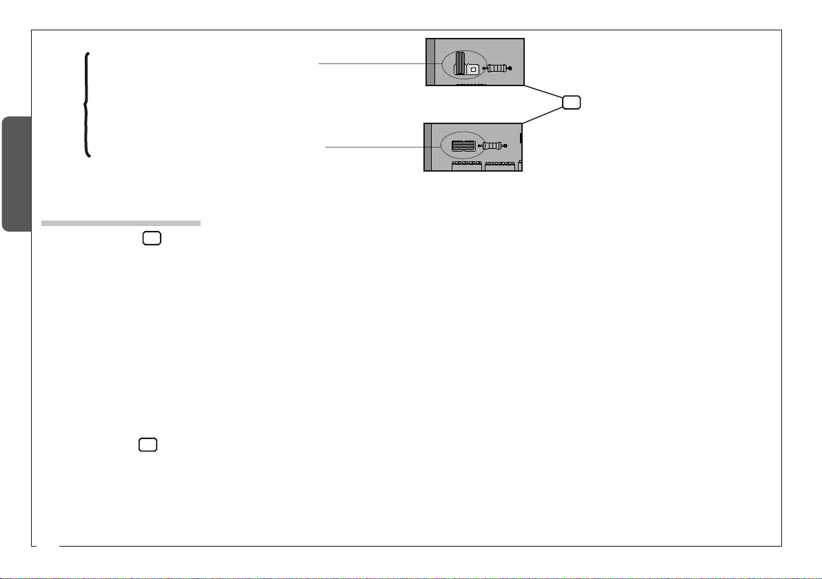
A. inserire la scheda AF esistente.
B. memorizzare la codifica sulla scheda base.
- La schedina AF deve essere inserita OBBLIGA-
TORIAMENTE in assenza di tensione, perché la scheda
madre la riconosce solo quando viene alimentata.
Memorizzazione
- Tenere premuto il tasto "CH1" sulla scheda base (il led di segnalazione lampeggia), con
un tasto del trasmettitore si invia il codice, il led rimarrà acceso a segnalare l'avvenuta
memorizzazione.
-Eseguire la stessa procedura con il tasto "CH2" associandolo con un altro tasto del
trasmettitore.
CH1 = Canale per comandi diretti ad una funzione della centralina del motoriduttore (co-
mando "solo apre" / "apre-chiude-inversione" oppure "apre-stop-chiude-stop", a seconda
della selezione effetuata sui dip-switch 2 e 3).
CH2 = Canale per comandi diretti ad un dispositivo accessorio collegato su B1-B2.
N.B.: Se in seguito si vuol cambiare codice, basta ripetere la sequenza descritta.
Regolazione trimmers
TrimmerFINEADJ/AMPSENS=Regolazione
finedelsensoreamperometricodurante la
marcia: min/max;
Trimmer AMP SENS = Regolazione
sensibilità amperometrica durante la
marcia: min/max;
Trimmer SLOWDOWN/AMP SENS =
Regolazione sensibilità amperometrica
durante il rallentamento: min/max;
Trimmer OPTIME=Regolazionedella zona
di arresto in battuta;
Trimmer ACT = Regolazione tempo
chiusura automatica: da 2" a 120";
Trimmer DELAY 2M = Ritardo chiusura del
motore M2: da 1" a 15";
'(/$<0
ŔŔ
$&7
ŔŔ
237,0(
),1($'-
$036(16
PD[PLQ
$036(16
PD[PLQ
6/2:'2:1
$036(16
PD[PLQ
Attenzione! Prima di intervenire all’interno dell’apparecchiatura, togliere la tensione di linea e scollegare le batterie (se inserite).
ef
ef
7
ITALIANO
I dati e le informazioni indicate in questo manuale sono da ritenersi suscettibili di modifica in qualsiasi momento e senza obbligo di preavviso da parte di CAME cancelli automatici s.p.a.
Attivazione del comando radio
A. inserire la scheda AF esistente.
B. memorizzare la codifica sulla scheda base.
- La schedina AF deve essere inserita OBBLIGA-
TORIAMENTE in assenza di tensione, perché la scheda
madre la riconosce solo quando viene alimentata.
Memorizzazione
- Tenere premuto il tasto "CH1" sulla scheda base (il led di segnalazione lampeggia), con
un tasto del trasmettitore si invia il codice, il led rimarrà acceso a segnalare l'avvenuta
memorizzazione.
-Eseguire la stessa procedura con il tasto "CH2" associandolo con un altro tasto del
trasmettitore.
CH1 = Canale per comandi diretti ad una funzione della centralina del motoriduttore (co-
mando "solo apre" / "apre-chiude-inversione" oppure "apre-stop-chiude-stop", a seconda
della selezione effetuata sui dip-switch 2 e 3).
CH2 = Canale per comandi diretti ad un dispositivo accessorio collegato su B1-B2.
N.B.: Se in seguito si vuol cambiare codice, basta ripetere la sequenza descritta.
Regolazione trimmers
TrimmerFINEADJ/AMPSENS=Regolazione
finedelsensoreamperometricodurante la
marcia: min/max;
Trimmer AMP SENS = Regolazione
sensibilità amperometrica durante la
marcia: min/max;
Trimmer SLOWDOWN/AMP SENS =
Regolazione sensibilità amperometrica
durante il rallentamento: min/max;
Trimmer OPTIME=Regolazionedella zona
di arresto in battuta;
Trimmer ACT = Regolazione tempo
chiusura automatica: da 2" a 120";
Trimmer DELAY 2M = Ritardo chiusura del
motore M2: da 1" a 15";
'(/$<0
ŔŔ
$&7
ŔŔ
237,0(
),1($'-
$036(16
PD[PLQ
$036(16
PD[PLQ
6/2:'2:1
$036(16
PD[PLQ
Attenzione! Prima di intervenire all’interno dell’apparecchiatura, togliere la tensione di linea e scollegare le batterie (se inserite).
ef
ef