RLB
www.came.com
Italiano
IT
English
EN
Français
FR
Русский
RU 2 x 1.5 mm² - 2 m max
ZL65
ZL60
FA00148M4A - ver.
2 - 04/2016
FA00148M4A
ITALIANO
Descrizione
Scheda per il funzionamento in caso di
blackout e per la ricarica delle batterie.
Le batterie rappresentate NON SONO
FORNITE.
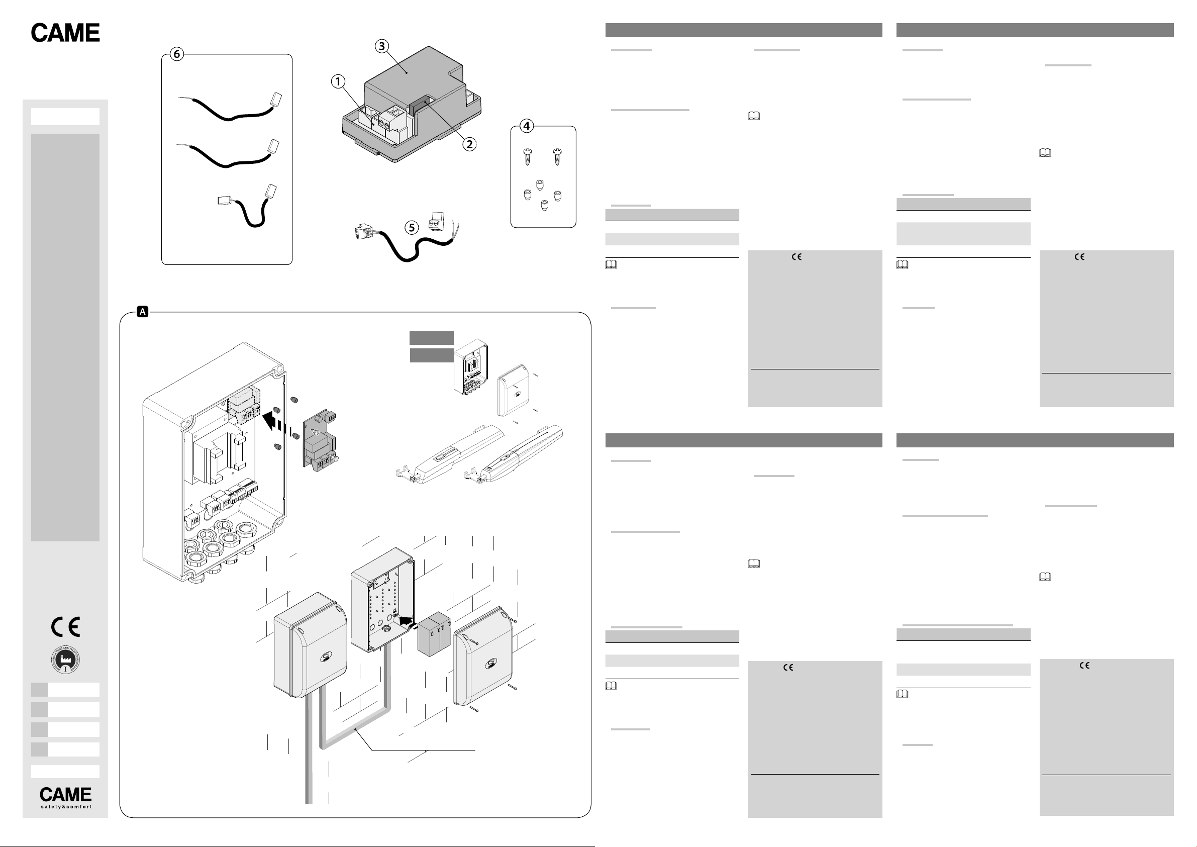
Composizione articolo
①- Scheda LB39
②- Fusibile 10 A
③- Contenitore scheda
④- Distanziali e viti per fissaggio
⑤- Cavo collegamento
⑥- Cavi collegamento batterie
(rosso = ⊕, nero = ⊖)
Dati tecnici
Tipo RLB
Assorbimento a riposo (mA) 75
Tensione di carica (V) 27
Corrente di carica max (mA) 400
Il numero di manovre di emergenza
garantite, dopo la prima, dipendono dallo
stato delle batterie.
Installazione
⚠Prima di qualsiasi operazione su quadri
o automazioni, togliere la tensione di linea.
Fissare la scheda LB39, senza conteni-
tore, nel quadro comando e inserire le bat-
terieinuncontenitoreesterno(119RIR315).
Collocare la scheda RLB e le batterie
dove indicato nelle immagini, a seconda
dell’automazione.
Collegamenti
Scollegareiltrasformatoredallascheda
elettronica e ricollegarlo alla scheda LB39.
Collegare la scheda LB39 alla scheda
elettronica con il cavo fornito.
Collegare le batterie con i cavi forniti.
Per l’installazione su quadri comando
(), prevedere cavi di sezione 1,5 mm2
per un massimo di 2 metri di lunghezza.
Dichiarazione - Came S.p.A. dichiara che
questo dispositivo è conforme ai requisiti es-
senziali e alle altre disposizioni pertinenti sta-
bilite dalla direttiva 2004/108/CE. Originale su
richiesta.
Dismissione e smaltimento. I componenti
dell’imballo (cartone, plastiche, etc.) sono as-
similabili ai rifiuti solidi urbani. I componenti
del prodotto (metalli, schede elettroniche, bat-
terie, etc.) vanno separati e dierenziati. Per
le modalità di smaltimento verificare le regole
vigenti nel luogo d’installazione. Non disperdere
nell’ambiente!
I DATI E LE INFORMAZIONI INDICATE IN QUESTO MANUA-
LE SONO DA RITENERSI SUSCETTIBILI DI MODIFICA IN
QUALSIASI MOMENTO E SENZA OBBLIGO DI PREAVVISO.
LE MISURE, SE NON DIVERSAMENTE INDICATO, SONO
IN MILLIMETRI.
ENGLISH
Description
Card for operation during power outages
and for recharging the batteries.
The batteries shown are NOT SUPPLIED.
Article composition
①- LB39 card
②- 10 A fuse
③- Card holder
④- Spacers and fastening screws
⑤- Connection cable
⑥- Battery connection cables
(red = ⊕, black = ⊖)
Technical data
Type RLB
Absorption when idle (mA) 75
Voltage when charging
(V) 27
Charging current max (mA) 400
The number of guaranteed emergency
maneuvers, after the first one, depends on
the state of the batteries.
Installing
⚠Before doing any work on electrical
panels or operators, cut o the mains
power supply.
Fit the LB39 card, without holder, into
the control panel and fit the batteries into
an external casing (119RIR315).
Place the RLB card and batteries where
shown in the images, depending on the
operator.
Collegamenti
Disconnect the transformer from the
control board and reconnect it to the
LB39 card.
Connect the LB39 card to the control
board using the supplied cable.
Connectthebatteriesusingthesupplied
cables.
To install onto control panels (),
set up cables with 1.5 mm section2for
2 meters in length at most.
Declaration - Came S.p.A. declares that
this device conforms to the essential, pertinent
requirements provided by directive 2004/108/
CE. An original copy is available on request.
Decommissioning and disposal.- The pack-
aging materials (cardboard, plastic, and so
on) should be disposed of as solid household
waste. The product components (metals; con-
trol boards, batteries, etc.) must be separated
from other waste for recycling. Check your local
laws to properly dispose of the materials. Do not
dispose of in nature!
THE DATA AND INFORMATION IN THIS MANUAL MAY BE
CHANGED AT ANY TIME AND WITHOUT NOTICE.
THE MEASUREMENTS, UNLESS OTHERWISE STATED,
ARE IN MILLIMETERS.
FRANÇAIS
Description
Carte pour le fonctionnement en cas de
coupure de courant et pour la recharge
des batteries.
Les batteries représentées NE SONT PAS
FOURNIES.
Composition article
①- Carte LB39
②- Fusible 10 A
③- Boîtier carte
④- Entretoises et vis de fixation
⑤- Câble de connexion
⑥- Câbles de connexion des batteries
(rouge = ⊕, noir = ⊖)
Données techniques
Type RLB
Absorption au repos (mA) 75
Tension de charge (V) 27
Courant de charge max. (mA) 400
Le nombre de manœuvres de secours
garanties, après la première, dépend de
l'état des batteries.
Installation
⚠Mettrehorstensionavanttouteinterven-
tion sur les tableaux ou les automatismes.
Fixer la carteLB39, sansboîtier,dans le
tableau de commande et introduire les bat-
teries dans un boîtier externe (119RIR315).
Loger la carte RLB et les batteries
comme indiqué sur les images en fonction
de l'automatisme.
Connexions
Déconnecter le transformateur de la
carte électronique et le reconnecter à la
carte LB39.
Connecter la carte LB39 à la carte
électronique avec le câble fourni.
Connecter les batteries avec les câbles
fournis.
Pour l'installation sur des tableaux de
commande (), prévoir des câbles d'une
section d'1,5 mm2pour une longueur
maximale de 2 mètres.
Déclaration - Came S.p.A. déclare que ce
dispositif est conforme aux exigences essen-
tielles et aux dispositions pertinentes établies
par la directive 2004/108/CE. Copie originale
disponible sur demande.
Mise au rebut et élimination.Les composants
de l’emballage (carton, plastiques, etc.) sont
assimilables aux déchets urbains solides. Les
composants du produit (métaux, cartes élec-
troniques, batteries, etc.) doivent être triés et
diérenciés. Pour les modalités d'élimination,
vérifier les normes en vigueur sur le lieu d'ins-
tallation. Ne pas jeter dans la nature !
LES DONNÉES ET LES INFORMATIONS CONTENUES
DANS CE MANUEL SONT SUSCEPTIBLES DE SUBIR DES
MODIFICATIONS À TOUT MOMENT ET SANS AUCUN
PRÉAVIS.
LES DIMENSIONS SONT EXPRIMÉES EN MILLIMÈTRES,
SAUF INDICATION CONTRAIRE.
РУССКИЙ
Описание
Плата аварийного питания для подклю-
чения и зарядки аккумуляторов.
Аккумуляторы, изображенные на ри-
сунке, НЕ ПРИЛАГАЮТСЯ.
Основные компоненты
①- Плата LB39
②- Плавкий предохранитель 10 A
③- Корпус платы
④- Дистанционные детали и крепеж-
ные винты
⑤- Кабель подключения
⑥- Провода подключения аккумуля-
торов
(красный = ⊕, черный = ⊖)
Технические характеристики
Модель RLB
Потребляемый ток в режиме
ожидания (мА) 75
Зарядное напряжение (В) 27
Макс. зарядный ток (мА) 400
Гарантированное количество ра-
бочих действий при кратковременном
отключении электроэнергии зависит от
состояния аккумуляторов.
Монтаж
⚠Перед проведением каких-либо на-
строек, регулировок или подключений
в блоках управления или автоматике
необходимо отключить сетевое элек-
тропитание.
Прикрепите плату LB39, без корпуса,
в блоке управления и вставьте аккуму-
ляторы во внешний корпус (119RIR315).
Установите плату RLB и аккумулято-
ры, как показано на рисунках, с учетом
автоматики.
Подключения
Отключите трансформатор от платы
и подключите его снова к плате LB39.
Подключите плату LB39 к плате
прилагаемым кабелем.
Подключите аккумуляторы прилага-
емыми проводами.
Для монтажа на блоки управления
() необходимо предусмотреть кабели
сечением 1,5 мм2при максимальной
длине не более 2 метров.
Декларация — Came S.p.A. заявляет,
что изделие соответствует основным тре-
бованиям и положениям, установленным
Директивой 2004/108/CE. Оригинал де-
кларации предоставляется по требованию.
Утилизация. Упаковочные материалы
(картон, пластмасса и т. д.) могут быть
утилизированы как бытовые отходы. Ма-
териалы и компоненты изделия (металл,
электронные платы, элементы питания и
т.д.) необходимо разделить перед утили-
зацией. Утилизацию изделия необходимо
проводить в соответствии с действующим
законодательством местности, в которой
производилась его эксплуатация. Не за-
грязняйте окружающую среду!
ВСЕ ДАННЫЕ И ИНФОРМАЦИЯ, СОДЕРЖАЩИЕСЯ
В ЭТОЙ ИНСТРУКЦИИ, МОГУТ БЫТЬ ИЗМЕНЕНЫ В
ЛЮБОЕ ВРЕМЯ И БЕЗ ПРЕДВАРИТЕЛЬНОГО УВЕДОМ-
ЛЕНИЯ.
ВСЕ РАЗМЕРЫ ПРИВЕДЕНЫ В ММ, ЕСЛИ НЕ УКАЗАНО
ИНОЕ.


