FA00164M4A - ver.
1 - 09/2015
ITALIANO
Avvertenze generali
•L’installazione deve essere effettuata da
personale qualificato ed esperto e nel pieno
rispetto alle normative vigenti.
•È vietato utilizzare il prodotto in modo improprio o
per scopi diversi da quelli previsti.
•Prima di eseguire i collegamenti, togliere
l’alimentazione dal dispositivo onnipolare.
Descrizione
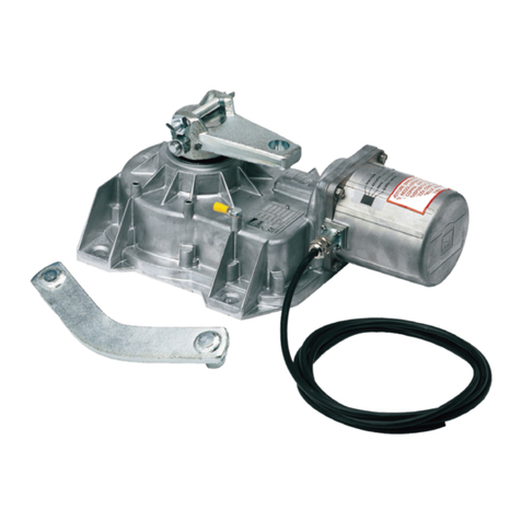
Finecorsa magnetico per cancelli scorrevole.
Dati tecnici
Tipo RSDN002
Grado di protezione (IP) 54
Intermittenza/Lavoro (%) SERVIZIO
INTENSIVO
Temperatura di esercizio (°C) -20 ÷ +55
Classe di isolamento
Peso (kg) 0,350
Descrizione delle parti
1. Magnete
2. Alette
3. Supporti
4. Sensore magnetico
5. Viti di fissaggio M6X20
6. Rondelle Ø 6
7. Viti senza testa M6X25
Installazione
Rimuovere il coperchio dell’automazione svitando le
viti laterali ().
Scollegare il micro del finecorsa meccanico a molla
dalla scheda elettronica e rimuoverlo dalla cassa
svitando la vite ().
Inserire il finecorsa magnetico nella cassa e
collegarlo ai morsetti F (filo blu) - FA (filo marrone) -
FC (filo nero) della scheda elettronica ().
⚠Assemblare le alette con i supporti come da
disegno.
Aletta magnetica di finecorsa in chiusura ().
Aletta magnetica di finecorsa in apertura ().
Determinazione dei punti di finecorsa
Con il motoriduttore sbloccato e con il cancello aperto
(circa 20 mm dalla battuta di arresto), inserire l’aletta
magnetica di finecorsa in apertura sulla cremagliera
tenendo il magnete a una distanza compresa tra 10 e
30 mm dal sensore magnetico ().
Fissare il supporto dell’aletta alla cremagliera con le
viti senza testa ().
Posizionare il magnete dell’aletta in perpendicolare
rispetto al sensore magnetico ().
Fissare l’aletta con la vite ().
Allo stesso modo, regolare l’aletta magnetica di
finecorsa in chiusura con il cancello chiuso ().
DICHIARAZIONE - CAME S.p.A. dichiara che questo prodotto
è conforme ai requisiti essenziali e alle altre disposizioni pertinenti
stabilite dalla direttiva 2006/42/CE e 2014/30/UE.
DISMISSIONE E SMALTIMENTO - I componenti dell’imballo
(cartone, plastica, etc.) sono assimilabili ai rifiuti solidi urbani. I
componenti del prodotto (metalli, schede elettroniche, batterie, etc.)
vanno separati e diff erenziati. Per le modalità di smaltimento verifi
care le regole vigenti nel luogo d’installazione.
NON DISPERDERE NELL’AMBIENTE!
I CONTENUTI DEL MANUALE SONO DA RITENERSI SUSCETTIBILI DI
MODIFICA IN QUALSIASI MOMENTO SENZA OBBLIGO DI PREAVVISO. LE
MISURE,SENON DIVERSAMENTE INDICATO,SONO INMILLIMETRI.
ENGLISH
General warnings
•The installation must be done by qualified, expert
technicians and in full compliance with applicable
laws and regulations.
•It is forbidden to use this product wrongfully or
for reasons other than its intended purpose.
•Before making any connections, cut off the mains
power supply from the omnipolar device.
Description
Magnetic limit-switch
Technical data
Type RSDN002
Protection rating (IP) 54
Duty cycle (%) INTENSIVE
USE
Operating temperature (°C) -20 ÷ +55
Insulation class
Weight (Kg) 0.350
Description of parts
1. Magnet
2. Tabs
3. Supports
4. Magnetic sensor
5. M6X20 fastening bolts
6. Ø 6 washers
7. M6X25 headless bolts
Installation
Remove the casing from the operator by turning the
side screws ().
Unplug the micro-switch for the spring-loaded
mechanical stop from the control board and remove it
altogether by loosening the screw ().
Fit the magnetic limit-switch into the casing and
connect it to terminals F (blue wire), FA (brown wire)
and FC (black wire) on the control board.).
⚠Assemble the tabs with the supports as shown in
the drawing.
Closing limit-switch magnetic tab ().
Opening limit-switch magnetic tab ().
Establishing the limit-switch points
With the gearmotor released and the gate open at
about 20 mm from the strike plate, fit the opening
limit-switch magnetic tab onto the rack keeping the
magnet between 10 and 30 mm from the magnetic
sensor ().
Fasten the tab support to the rack using the headless
bolts ().
Place the tab magnet perpendicularly to the magnetic
sensor ().
Tighten the bolt to fasten the tab ().
Likewise, set the closing limit-switch magnetic tab
with the gate closed, this time. ().
DECLARATION - CAME S.p.A. declares that this device
conforms to the essential, pertinent requirements provided
by directives 2006/42/CE and 2014/30/UE.
DISMANTLING AND DISPOSALThe packaging materials
(cardboard, plastic, and so on) should be disposed of as solid
household waste. The product components (metals; control boards,
batteries, etc.) must be separated from other waste for recycling.
Check your local laws to properly dispose of the materials.
DO NOT DISPOSE OF IN NATURE!
THE CONTENTS OF THISMANUAL MAYBE CHANGED ATANY TIME
WITHOUT PRIOR NOTICE.
THE MEASUREMENTS, UNLESS OTHERWISE STATED, ARE INMILLI-
METERS.
FRANÇAIS
Instructions générales
•L’installation doit être effectuée par du personnel
qualifié et dans le plein respect des normes en
vigueur.
•Il est interdit d'utiliser le produit de façon
impropre ou à des fins autres que celles prévues.
•Avant d'effectuer les branchements, mettre le
dispositif omnipolaire hors tension.
Description
Fin de course magnétique pour portail coulissant.
Données techniques
Type RSDN002
Degré de protection (IP) 54
Intermittence/Fonctionnement (%) SERVICE
INTENSIF
Température de fonctionnement (°C) -20 à +55
Classe d'isolation
Poids (Kg) 0,350
Description des parties
1. Aimant
2. Ailettes
3. Supports
4. Capteur magnétique
5. Vis de fixation M6X20
6. Rondelles Ø 6
7. Vis sans tête M6X25
Installation
Enlever le couvercle de l'automatisme en dévissant les
vis latérales ().
Déconnecter le micro-interrupteur du fin de course
mécanique à ressort de la carte électronique et
l'extraire de la caisse en dévissant la vis ().
Introduire le fin de course mécanique dans la caisse et
le connecter aux bornes F (fil bleu) - FA (fil marron) -
FC (fil noir) de la carte électronique ().
⚠Assembler les ailettes et les supports comme
illustré.
Ailette magnétique de fin de course en fermeture ().
Ailette magnétique de fin de course en ouverture ().
Détermination des points de fin de course
Avec motoréducteur débloqué et portail ouvert (à
environ 20 mm de la butée d'arrêt), introduire l'ailette
magnétique de fin de course en ouverture sur la
crémaillère en maintenant l'aimant à une distance
comprise entre 10 et 30 mm par rapport au capteur
magnétique ().
Fixer le support de l'ailette à la crémaillère à l'aide des
vis sans tête ().
Positionner l'aimant de l'ailette perpendiculairement
au capteur magnétique ().
Fixer l'ailette à l'aide de la vis ().
Régler de la même manière l'ailette magnétique de fin
de course en fermeture avec portail fermé ().
DÉCLARATION - CAME S.p.A. déclare que ce produit est
conforme aux exigences essentielles et aux dispositions
pertinentes établies par les directives 2006/42/CE et 2014/30/UE.
MISE AU REBUT ET ÉLIMINATION - Les composants de
l’emballage (carton, plastique, etc.) sont assimilables aux déchets
urbains solides. Les composants du produit (métaux, cartes
électroniques, batteries, etc.) doivent être triés et diff érenciés. Pour
les modalités d'élimination, vérifi er les normes en vigueur sur le
lieu d'installation.
NE PAS JETER DANS LA NATURE !
LE CONTENU DU MANUEL EST SUSCEPTIBLE DE SUBIR DES MODIFICA-
TIONS À TOUT MOMENT ETSANS AUCUN PRÉAVIS.
LES DIMENSIONS SONT EXPRIMÉES EN MILLIMÈTRES, SAUF
INDICA-TION CONTRAIRE.
РУССКИЙ
Общие правила безопасности
•Монтаж должен производиться
квалифицированным персоналом в полном
соответствии с требованиями действующих
норм безопасности.
•Запрещается использовать изделие не
по назначению или в целях, отличных от
указанных.
•Перед тем как приступить к выполнению
электрических подключений, отключите
электропитание с помощью главного
выключателя.
Описание
Магнитные концевые выключатели для
автоматики откатных ворот.
Технические характеристики
Модель RSDN002
Класс защиты (IP) 54
Интенсивность использования (%) ИНТЕНСИВНОГО
ИСПОЛЬЗОВАНИЯ
Диапазон рабочих температур(°C) -20 – +55
Класс изоляции
Масса (кг) 0,350
Основные компоненты
1. Магнит
2. Держатель магнита
3. Крепление
4. Магнитный датчик
5. Крепежные винты M6X20
6. Шайбы Ø 6
7. Стопорные винты M6X25
Монтаж
Снимите крышку с привода, отвернув боковые
саморезы ().
Отсоедините провода механических концевых
выключателей от платы управления и вытащите
блок концевых выключателей из корпуса,
отвернув винт ().
Вставьте магнитный датчик в корпус и
подключите его к контактам F (синий провод),
FA (коричневый провод), FC (черный провод)
платы управления ().
⚠Соедините держатели с креплениями, как
показано на рисунке.
Магнит установки крайнего положения
закрывания ().
Магнит установки крайнего положения
открывания ().
Настройка крайних положений
Разблокировав привод и открыв ворота (на
расстояние 20 мм от механического упора),
установите крепление магнита открывания
на зубчатую рейку, расположив магнит на
расстоянии от 10 до 30 мм от магнитного датчика
().
крепление магнита открывания зубчатой рейке
стопорными винтами ().
Установите магнит перпендикулярно магнитному
датчику ().
Зафиксируйте держатель винтом ().
Аналогичным образом установите магнит
крайнего положения закрывания при закрытых
воротах ().
ДЕКЛАРАЦИЯ - CAME S.p.A. Came Cancelli Automatici
S.p.A. заявляет, что это устройство соответствует основным
требованиям и положениям, установленным Директивами
2006/42/CE и 2014/30/UE.
УТИЛИЗАЦИЯ - Упаковочные материалы (картон, пластмасса
и т. д.) могут быть утилизированы как бытовые отходы.
Материалы и компоненты изделия (металл, электронные
платы, элементы питания и т.д.) необходимо разделить перед
утилизацией. Утилизацию изделия необходимо проводить в
соответствии с действующим законодательством местности,
в которой производилась его эксплуатация.
НЕ ЗАГРЯЗНЯЙТЕ ОКРУЖАЮЩУЮ СРЕДУ!
ВСЕ ДАННЫЕ, СОДЕРЖАЩИЕСЯ В ЭТОЙ ИНСТРУКЦИИ, МОГУТ
БЫТЬ ИЗМЕНЕНЫ В ЛЮБОЕ ВРЕМЯ И БЕЗ ПРЕДВАРИТЕЛЬНОГО
УВЕДОМЛЕНИЯ.
ВСЕ РАЗМЕРЫ ПРИВЕДЕНЫ В ММ, ЕСЛИ НЕ УКАЗАНО ИНОЕ.


