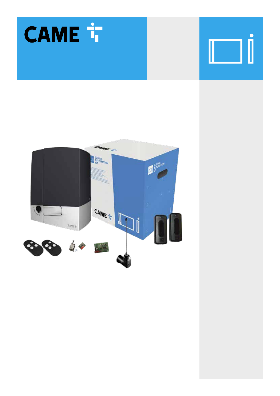
CAME BXV400GS User manual

CAME.COM/UK
BXV400GS
kit
Complete kit for a sliding gate weighing
up to 400kg / max. width 14m
QUICK SETUP GUIDE
TO BE READ IN CONJUNCTION WITH THE FULL INSTRUCTION MANUAL

CONTENTS
AF43S
Radio Frequency Card
BXV04AGS
Motor with built-in ZN7
control panel
x2
BXV400GS: KIT CONTENTS
DIR10
Pair of Photocells
top-a433n
Tuned Antenna
topd4rks
Rolling code Transmitter
RGSM001S
Gateway Module
RSE
Connection Card
SIM
May be preinstalled in
RGSM001S
1Kit Contents
2Safety Instructions
3Typical Gate Setup
4Geometry
5Manual Release Instructions
6Wiring Diagram
7Pre-installed SIM Card
8Initial Power On
9Commissioning the RGSM
10 Commissioning via App
11 Commissioning via Panel
12 Safety Options
13 Replacing the SIM Card
14 Optional Accessories

2SAFETY INSTRUCTIONS
When correctly installed in compliance to installation instructions and adhering to all
current electrical, mechanical and manufacturer regulations, your automation system
will provide a high degree of safety and problem free operation.
Please take note of the following warnings that must be followed in order to
prevent accidents during your gate operation:
• Do not allow children to play near the gate.
• Keep all remote control operating devices out of the reach of children.
• Do not pass through the gate whilst in operation. Wait until they are fully open before passing through.
• Do not stop unnecessarily when passing through the gate.
• Keep feet away from the bottom of the gate during operation.
• Do not operate the gate by remote control unless they are in view.
• Do not attempt to block or interfere with the gate movement during operation.
• Under no circumstances should you attempt to modify the gate automation system.
• Ensure that your gate is serviced at 3 to 12 month intervals (dependent on number of openings) by your installation/
maintenance company.
• Report any signs of malfunction to your installation/maintenance company immediately.
• In the case of malfunction, isolate the power supply, release any additional locking mechanism, manually open the
gate (see manual release instruction booklet) and call your installation/maintenance company.
• If you are in any doubt regarding the operation of your gate, call your installation/maintenance company.

3 TYPICAL GATE SETUP
PHOTOCELLS
• The photocells are used in pairs, one transmitter and one receiver.
• They should be installed between 500-600mm from the ground, facing each other.
• Power for the photocells is taken from the control panel 24v AC.
• The maximum range of the photocell should always be observed.
When the photocell beam is broken, the control panel can be programmed on how to react.
Please see ‘Safety’ section for more information.
1
9
7
8
2
5
3
4
6
OUTSIDE OF GATES
INSIDE OF GATES
10
11
12
8
1BXV Motor 5Selector Keypad (optional) 9Photocell column (optional accessory)
2Limit switch fins 6Photocells (on outside of gate posts) 10 Slide guides
3Reception Antenna 72nd set of Photocells (optional) 11 Rack
4Flashing Light (optional) 8Mechanical End Stop (not supplied) 12 Sensitive safety-edge
CONTROL PANEL
• The control panel is integral to the motor and is accessed by removing the outer cover.
• The control panel is protected by a board-protection cover which will need to be removed for initial wiring.
Only a competent service provider should open the enclosure
and adjust the settings.

4 GEOMETRY
Max Leaf Length (m) Max Leaf Weight (kg)
14 400
Preliminary checks
gate GEOMETRY
Tick
1. Ensure that all surfaces are perfectly level (Do not install on slopes)
2. Foundation frame dug out
3. Set up the corrugated tubes needed for the wiring coming out of the junction pit.
4. Use Ø 40 mm corrugated tubes to connect the gearmotor to the accessories
5. Prepare a Ø 20 mm tube to run the release cord through A.
6. Use Ø 40 mm corrugated tubes to connect the gearmotor to the accessories
The number of tubes depends on the type of system and the accessories that are going to be tted
INSTALLATION
Please refer to the full manual for installing the motor, rack and setting travel end points
290
145 145
300
170
250
85 85
95
212
160
106
1-2mm
117
1-2mm
1-2mm. The rack and pinion should mesh.
Do not allow the rack to rest on the pinion.
The gate motor must be installed parallel to the gate.

5 MANUAL RELEASE
To manually release the gates:
1. Open the lock cover cap A1 .
2. Insert the triangular key
provided A2 and turn to
release the lever A3 .
3. Turn the lever to the vertical
position to release the gate
mechanism A4 .
4. With your other hand firmly
open the gate. The gate
should be manually released.
Now fully open the gate
carefully at the same speed
as the automatic operator.
5. To re-engage, close the gate
and return the lever to the
horizontal position B2 and
push in B3 while turning the
key to lock it in pace B1 .Take
the key out and replace the
cap B4 .
6. Attempt to manually move
the gate to ensure it is fully
engaged.
The BXV sliding gate operator has a manual release system which pops out when the
motor is unlocked.
Basic Maintenance: Hints & Tips
• If a ground track is fitted, ensure the track is always
clear of debris.
• Lubricate manual release compartment and key
mechanism.
• Manually release the gates at least once per month.
ALWAYS isolate the power supply as
instructed by your installer (even in a
power cut).
Release any additional locking
device fitted to the gate (eg. electric
lock etc).
a
B

6 wiring diagram
ZN7
Control Panel
+ -
10 2 TX C NC TX 2
RX TX
DIR
Photocells
Cable/length
RX 4 Core 0.5mm Flex
TX 4 Core 0.5mm Flex
1m - 30m
1 2 3P 7 10 TS 2 CX CY
M N
FC FA F + E -
L N
AGNDBA BS1 GND
10 11 E 5Z4 C
AF43S
Plug-in
TOP-A433N
Antenna
Cable/length
RG58
Max. 5m
RSE
Set RSE jumper
to OFF
1 2 3P 7 10 TS 2 CX CY
M N
FC FA F + E -
L N
AGNDBA BS1 GND
10 11 E 5Z4 C
RGSM001S
Gateway Module
Cable/length
Max 3m power
10 2 A B GND
Mains Supply
230 V AC
Cable/length
1m - 20m = 3 Core 1.5mm Flex
20m - 30m = 3 Core 2.5mm Flex

TITLE7pre-installed sim card
The pre-installed SIM card is an IOT/M2M multi SIM complete with 480MB data allowance and 3 year life term.
Under average usage of 3-4 gate manoeuvres per day, the data should last approximately 3 years.
In case you use up the 480MB data volume before the end of the 3-year term, you can easily add another 480MB data
volume by making a top-up, details of which can be found here:
www.cameconnect.co.uk/gsmmodule
Due to situations outside of our control, CAME cannot guarantee signal strength or availability and therefore will not be
held liable for lack of service.
came automation
internet
came cloud
setup app
for the installer
GET IT ON
App Store
GET IT ON
automation app
for the end user
GET IT ON
App Store
GET IT ON
System Frequency Approx. Movements Est. SIM Life Based on Usage
Occasional Usage Approx. 5 gate manoeuvres per
week
4-7 Years*
Average Usage** Approx. 3-4 gate manoeuvres
per day
3-4 Years
High Usage Approx. 5+ gate manoeuvres per
day, multiple scenarios running
1-3 Years
* SIM will expire after 3-4 years. (CAME guarantees 3 years with some tolerance for shelf life consideration)
** We anticipate SIM provided will have sufficient data for Average Usage (as shown above) lasting approx. 3 years

TITLE
7pre-installed sim card
The pre-installed SIM card is an IOT/M2M multi SIM complete with 480MB data allowance and 3 year life term.
Under average usage of 3-4 gate manoeuvres per day, the data should last approximately 3 years.
In case you use up the 480MB data volume before the end of the 3-year term, you can easily add another 480MB data
volume by making a top-up, details of which can be found here:
www.cameconnect.co.uk/gsmmodule
Due to situations outside of our control, CAME cannot guarantee signal strength or availability and therefore will not be
held liable for lack of service.
came automation
internet
came cloud
setup app
for the installer
GET IT ON
App Store
GET IT ON
automation app
for the end user
GET IT ON
App Store
GET IT ON
System Frequency Approx. Movements Est. SIM Life Based on Usage
Occasional Usage Approx. 5 gate manoeuvres per
week
4-7 Years*
Average Usage** Approx. 3-4 gate manoeuvres
per day
3-4 Years
High Usage Approx. 5+ gate manoeuvres per
day, multiple scenarios running
1-3 Years
* SIM will expire after 3-4 years. (CAME guarantees 3 years with some tolerance for shelf life consideration)
** We anticipate SIM provided will have sufficient data for Average Usage (as shown above) lasting approx. 3 years
8initial power ON
OUT1OUT2
Keycode
123456789ABCDE F
MATR
54051 6
300mAE GSM – 900 33dBm
DCS – 1800 30dBm
869.5MHz 14dBm
24V
CONNECT
123 4
GND
A
N
T
10+
2
COM
IN2
COM
IN1
B
A
–
1A 30V
RGSM001S
1 2
1GSM LED (Blue)
After a few seconds the LED will flash 1x/sec indicating the RGSM001S is registered on a GSM network.
2POWER LED (Green)
The LED will flash 5x/sec indicating the RGSM001S is not yet configured on the Connect platform
Power on the control board.
Installer Tip
If the RGSM001S is located
in a concealed area and a low
GSM signal observed a 2m
extension cable and bracket is
available to purchase.
This then allows the aerial to
be located in a more suitable
position. Part No:
806SA-0050

TITLE9 commissioning the rgsm
3.1 Open the App and log in
using your technician details
as registered.
3.2 Select “CAME Connect
connection”.
3.3 Select “Site
management”.
3.4 Fill in a site “Name” and
“Description” and then press
“Add”.
2.1 Select “Register as
technician”.
2.2 Fill in your details and
then “Confirm”.You will
receive an email containing
your log in information
and request to confirm the
account. Should the email not
arrive, please check your junk
folder.
download the
connect setup app
adding the rgsm gateway
to your technician account
technician
connect setup app
1
3
2
If you have an existing account, please move to step 3.
Important!
The installation must be carried out
by skilled and qualified personnel
Mr Wilson, Sills Road, DE74 2US
1.1
GET IT ON
App Store
GET IT ON
Installer Tip
The Name and Description entered
here, can be used to identify the
site location.
Name: Mr Wilson, Sills Rd, DE74 2US
Description: Mr Wilson, Sills Rd,
DE74 2US
This shows in the Installers
Setup App, under the site
management list.

TITLE9 commissioning the rgsm
3.8 Manual Add
Enter the “Keycode” located on the
front of the RGSM0001S. Enter a
“Name” and “Description” followed
be “Add”.
3.5 Select the site you have
created.
3.6 Press “Add gateway”. 3.7 Press ‘Manual Add’.
OUT1OUT2
Keycode
123456789ABCDE F
MATR
54051 6
300mAE GSM – 900 33dBm
DCS – 1800 30dBm
869.5MHz 14dBm
24V
CONNECT
123 4
GND
A
N
T
10+
2
COM
IN2
COM
IN1
B
A
–
1A 30V
RGSM001S
1 2
3
troubleshooting
If you have any problems
setting up your RGSM, visit our
troubleshooting page:
123456789ABCDEF
SIM ID 8988228066602040825
Mr Wilson, Sills Rd, DE74 2US
3.9 The RED 3and GREEN 2LED’s will now be
on solid and the BLUE 1 flashing 1x/sec.
CONGRATULATIONS - the RGSM001S has now
been successfully added to the Connect platform
OUT1OUT2
Keycode
123456789ABCDE F
MATR
54051 6
300mAE GSM – 900 33dBm
DCS – 1800 30dBm
869.5MHz 14dBm
24V
CONNECT
123 4
GND
A
N
T
10+
2
COM
IN2
COM
IN1
B
A
–
1A 30V
RGSM001S
If you intend to retain control
of the SIM for top up
If, as the installer, you intend to retain control of the SIM
for top up purposes, we recommend that you complete
the ‘Name’ eld with information relating to the customer,
property or site and in the ‘Description’ eld you insert
the SIM number which will give you full visibility of the site
information and the description in the installer SETUP app.
However, If you are transferring
the SIM control to your end user
If you intend to transfer control of the SIM for top up
purposes to your end user, we recommend that the
Device Name should be labeled with the SIM number to
provide your end user long term visibility in the dedicated
end user Automation App.
Please Note:
The ‘Description’ eld is not visible in the end user
Automation App, therefore any information contained
within that eld will not be available to the end user
after handover. The description eld is only visible in the
Installer SETUP App.

TITLE
Encoder
Frog - F4024E
M1 + M2
10 COMMISSIONING VIA APP
Select the device you have
just created.
Select Quick Setup. Select Yes. Ensure direction of motor and
motor type are set.
Select the 3 dots. Select add automation. Select Manual Add. Select BXV – ZN7 from the
drop-down list.
Enter a name and description,
then press Add.
adding
automation
1
BXV - ZN7 - Automation for sliding gates
400 Kg
Front Gates
Front Gates
1
Installer Tip
The Name and Description entered
here, can be used to identify the
gate location
Name: Front Gates
Description: Front Gates
This shows under the
customers Automation App
on the main display

TITLE10 COMMISSIONING VIA APP
When the gate has successfully
calibrated, it will automatically
display the dialog box shown
below. Select Yes.
Select Add. Select either Local Acquisition
or Add with QR Code.
If you pressed Local Acquisition,
the screen will change to the one
shown here. Select the button on
the fob and it will add the button
straight onto the control panel.
Select OK. Set the safety inputs (please
refer to section 12 for
options). Select Next.
Select Calibrating Travel.

10 COMMISSIONING VIA APP
Select the back button to return
to the main menu.
Once it has been accepted on
the control panel It will display
the above screen. Enter a
Name and select the correct
function for the fob. Select
Save. Repeat this process for
all fobs.
Select the back button to
return to the main menu.
If you select ADD via QR
Code, the app will open the
devices camera enabling
scanning of the QR code on
the fobs packaging.
Once the QR code has been
scanned, enter a Name and
select the correct function
for each button on the fob. If
you wish for a certain button
to not be active, then untick
the check box for that button.
Select Confirm. Repeat this
process for all fobs.

TITLE
10 COMMISSIONING VIA APP
Accept the transfer request
directly from the email
received by the customer.
If the user has not previously
registered, select REGISTER
AS USER.
Complete the registration
details.
Finally, download the
Automation App.
On first login you will be
prompted to accept the
gateway.
You will then be presented
with control options for your
automation.
To transfer to a customer,
select the 3 dots.
Select Transfer site Enter customer details you
wish to transfer to.
Select confirm. The customer
will get an email asking to
confirm the account.
transfer to
customer
2
name@mycustomer.co.uk
Firstname
Lastname
GET IT ON
App Store
GET IT ON

TITLE11 commissioning via panel
Should the gates not operate as suggested above,
call CAME helpline 0115 921 0430 for technical support.
Safety inputs should now be configured and the
gate force tested as required. Please refer to the
full manual to complete the commissioning.
Ensure the wiring is complete (refer to the wiring diagram) & any required physical stops are set before
commencing with programming Tick
1. Power on the control panel.
2. Press and hold the for 2 seconds to access programming ( F1 appears on the display)
3. Disable total stop – F1 – OFF
4. Disable safety inputs – F2& F3– OFF
5. Set the opening direction F54– OFFleft, ONright
(viewed from the inside of the property looking out).
6. Set the motor type – A1 – 1
7. Setup the encoder – A3– ON
The Gates will now perform a close and open cycle.
8. Exit the programming using the button.
9. Check the gate operation by pulsing across connections 2& 7, the gate will close.
Please refer to the main manual for:
Changing automatic closing time, adjusting encoder settings if required
button - used to perform the following operations:
• Exit the menu
• Delete the changes
• Go back to the previous screen
buttons - used to perform the following operations:
• Navigate the menu
• Increase or decrease values
button - used to perform the following operations
• Access menus
• Confirm a choice
1
2
3
Important!

TITLE11 commissioning via panel
Should the transmitter not operate as suggested above,
call CAME helpline 0115 921 0430 for technical support.
add a transmitter button
1. Press and hold the button for 2 seconds to access programming. ( F1 appears on the display).
2. Add a transmitter button - U1
3. Choose the function to be assigned to the button
1 = Step-by-step
2= Sequential
3= Open
4= Partial opening
4. A flashing number will now appear on the screen.
5. Press and release a button on a transmitter, the number on the screen will increment by one for
each button pressed. A maximum of 250 individual buttons can be saved.
remove a transmitter button
1. Press and hold the button for 2 seconds to access programming. ( F1 appears on the display).
2. Remove a transmitter button - U2– ON
3. Use the arrow buttons to choose the number associated with the transmitter button you wish to remove.
“CLR” will appear to confirm deletion
remove all transmitters
1. Press and hold the button for 2 seconds to access programming. ( F1 appears on the display).
2. Remove all transmitters – U3– ON
All transmitters will be deleted.
transmitter radio decoding
1. Press and hold the button for 2 seconds to access programming. ( F1 appears on the display).
2. Remove a transmitter button – U4
3. Choose the type of radio coding for the transmitters
1 = All decoding (default)
2= Rolling code
4= TW key block
Ensure the AF card is fitted (refer to the wiring diagram).

TITLE12 SAFETY options
FUNCTIONS > CX Input, CY Input
SAFETY INPUTS
If during the reverse motion a different safety is triggered the automation will perform the appropriate action for the new triggered
safety, should multiple safeties be triggered at the same time the automation will be halted at its current position.
C1 REOPENING DURING CLOSING
• When the automation is in its closing cycle and the safety circuit is triggered the automation will stop and reverse its motion until it reaches its
fully open position again.
• If the auto closing option is enabled and the safety is no longer triggered the auto closing countdown will commence, once completed the
automation will start the closing cycle again.
• If the auto closing option is not enabled the automation will return to the fully open position awaiting another activation from a command device.
SENSITIVE EDGES
C2 RECLOSING DURING OPENING
• When the automation is in its opening cycle and the safety circuit is triggered the automation will stop and reverse its motion until it reaches its
fully closed position again.
• Once the automation has reached the fully closed position it will require another activation from a command device to restart.
C3 PARTIAL STOP
• When the automation is in its opening cycle and the safety circuit is triggered the automation will stop.
• If the auto closing option is enabled and the safety is no longer triggered the auto closing countdown will commence, once completed the
automation will start closing the device.
C4 OBSTRUCTION WAIT
• When the automation is in either its opening or closing cycle and the safety circuit is triggered the automation will stop.
• Once the safety is no longer triggered the automation will carry on the cycle it was performing at the time it was interrupted.
C7 REOPENING DURING CLOSING
• When the automation is in its closing cycle and the safety circuit is triggered the automation will reverse its motion until it reaches its fully open
position again.
• If the auto closing option is enabled and the safety is no longer triggered the auto closing countdown will commence, once completed the
automation will start the closing cycle again.
• If the auto closing option is not enabled the automation will return to the fully open position awaiting another activation from a command device.
C8 RECLOSING DURING OPENING
• When the automation is in its opening cycle and the safety circuit is triggered the automation will reverse its motion until it reaches its fully
closed position again.
• Once the automation has reached the fully closed position it will require another activation from a command device to restart.
The above sequence will be attempted 3 times before the automation is halted, the automation will then
require activation from a command device to restart.

12 SAFETY options
FUNCTIONS > CX Input, CY Input
SAFETY INPUTS
If during the reverse motion a different safety is triggered the automation will perform the appropriate action for the new triggered
safety, should multiple safeties be triggered at the same time the automation will be halted at its current position.
C1 REOPENING DURING CLOSING
• When the automation is in its closing cycle and the safety circuit is triggered the automation will stop and reverse its motion until it reaches its
fully open position again.
• If the auto closing option is enabled and the safety is no longer triggered the auto closing countdown will commence, once completed the
automation will start the closing cycle again.
• If the auto closing option is not enabled the automation will return to the fully open position awaiting another activation from a command device.
SENSITIVE EDGES
C2 RECLOSING DURING OPENING
• When the automation is in its opening cycle and the safety circuit is triggered the automation will stop and reverse its motion until it reaches its
fully closed position again.
• Once the automation has reached the fully closed position it will require another activation from a command device to restart.
C3 PARTIAL STOP
• When the automation is in its opening cycle and the safety circuit is triggered the automation will stop.
• If the auto closing option is enabled and the safety is no longer triggered the auto closing countdown will commence, once completed the
automation will start closing the device.
C4 OBSTRUCTION WAIT
• When the automation is in either its opening or closing cycle and the safety circuit is triggered the automation will stop.
• Once the safety is no longer triggered the automation will carry on the cycle it was performing at the time it was interrupted.
C7 REOPENING DURING CLOSING
• When the automation is in its closing cycle and the safety circuit is triggered the automation will reverse its motion until it reaches its fully open
position again.
• If the auto closing option is enabled and the safety is no longer triggered the auto closing countdown will commence, once completed the
automation will start the closing cycle again.
• If the auto closing option is not enabled the automation will return to the fully open position awaiting another activation from a command device.
C8 RECLOSING DURING OPENING
• When the automation is in its opening cycle and the safety circuit is triggered the automation will reverse its motion until it reaches its fully
closed position again.
• Once the automation has reached the fully closed position it will require another activation from a command device to restart.
The above sequence will be attempted 3 times before the automation is halted, the automation will then
require activation from a command device to restart.
13 replacing the sim card
A third party SIM card may be used, for example, if an existing SIM card is available or the current SIM data contract
expires.
To insert a SIM card please do the following:
With the power switched OFF to the control panel, remove the RGSM casing, slide out the existing SIM card and
fit the replacement SIM card into the slot. Replace the casing and power up the control panel.
Send an SMS to the telephone number of the SIM, reporting the APN details. Access Point Name – ask the service
provider for APN details e.g. APN:pp.vodafone.co.uk Capital, lowercase letters and punctuation must be respected
The SIM must be capable of 2G data transmission and have the PIN code disabled.
Full instructions for the RGSM001S module
can be found be visiting:
https://docs.came.com/pdf/FA01289M4A.pdf

14 optional ACCESSORIES
For more kit accessories please contact Sales on 0115 9210 430
Code(s) Description
RADIO KEYPAD SELECTORS
806SL-0170 SELT1W4G - Surface-mounted, 433.92 MHz radio-frequency keypad selector, 12-keys, with blue backlighting. 25 savable
codes and password to access the programming mode. Settable in Rolling Code or Fixed Code mode. RAL7024 Grey colour.
806SL-0180 SELT1W8G - Surface-mounted, 868.35 MHz radio-frequency keypad selector, 12-keys, with blue backlighting. 25 savable
codes and password to access the programming mode. Settable in Rolling Code or Fixed Code mode. RAL7024 Grey colour.
001AF868 Plug-in 868.35 MHz radio frequency control card.
Required for 806SL-0180.
BLUETOOTH SELECTORS
806SL-0210 SELB1SDG1 - Surface-mounted with blue backlighting, for 15 users. RAL7024 Grey colour.
806SL-0240 SELB1SDG2 - Surface-mounted with blue backlighting, for 50 users. RAL7024 Grey colour.
806SL-0250 SELB1SDG3 - Surface-mounted with blue backlighting, for 250 users. RAL7024 Grey colour.
TRANSPONDER SELECTORS
806SL-0300 SELR1BDG - Surface-mounted Bus transponder reader for cards, keyfobs and TAG (Manchester protocol) with blue
backlighting. RAL7024 Grey colour.
806SL-0310 SELR2BDG - Flush-mounted Bus transponder reader for cards, keyfobs and TAG (Manchester protocol) with blue
backlighting. RAL7024 Grey colour.
001R700 Programming board and access control management when used with transponder.
Required for 806SL-0300 and 806SL-0310.
HARDWIRED KEYPAD SELECTORS
806SL-0280 SELT1BDG - Surface-mounted 12 button Bus keypad with blue backlighting.
RAL7024 Grey colour.
806SL-0290 SELT2BDG - Flush-mounted 12 button Bus keypad with blue backlighting.
RAL7024 Grey colour.
001R800 Control board for programming and access-control management via keypad selectors.
Required for 806SL-0280 and 806SL-0290.
Table of contents
Other CAME Gate Opener manuals
Popular Gate Opener manuals by other brands

Automatic Technology Australia
Automatic Technology Australia Elite Installation instructions and owner's manual

Proteco
Proteco MyGate myaster Installation and use manual

FAAC
FAAC 750 Standard installation manual

FAAC
FAAC Night ONE Day manual

BFT
BFT P7 quick start guide

Topens
Topens Casar MT8012 user manual

BFT
BFT DEIMOS BT H QSC Installation and user manual

SEA
SEA ALPHA Series INSTALLATION MANUALS AND SAFETY INFORMATION

Nice
Nice ARIA Instructions and warnings for installation

DKS
DKS 9310 owner's manual

SOMFY
SOMFY SGS 201 Operating and installation guide

Eagle Access Control Systems
Eagle Access Control Systems X9S Installation & owner's manual