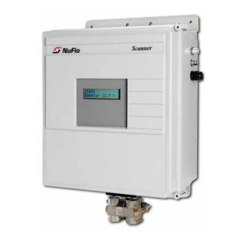
Cameron NUFLO EZ-IN Series User manual

NUFLO™
EZ-IN®Series
Turbine
Flowmeter
Installation Manual
Part No. 9A-100062997, Rev. 01
Measurement Systems
Class I, Group A, B, C, D, Division I
Complies with ASME Standard B31.3

EZ-IN®Series BF Turbine Flowmeter Manual
Part No. 9A-100062997, Rev. 01
September 2008
© 2008 Cameron International Corporation (“Cameron”)
Printed in USA
All Rights Reserved

iii
Table of Contents
Introduction................................................................................................ 5
Installation .............................................................................................. 10
Precautions ....................................................................................... 10
Installation Procedure ....................................................................... 11
Calibration ............................................................................................... 12
Maintenance and Repairs........................................................................ 14
Removing the Meter from the Pipeline.............................................. 14
Disassembling the Hex-Body Meter ................................................. 15
Reassembling the Hex-Body Meter .................................................. 16
Disassembling the Round-Body Meter ............................................. 19
Reassembling the Round-Body Meter .............................................. 20
Returning the Meter to the Pipeline .................................................. 23
Specications and Parts Lists.................................................................. 24
Temperature and Pressure Ratings .................................................. 24
Flow Ranges ..................................................................................... 24
Internal Components Repair Kit for Hex-Body Meters...................... 25
EZ-IN®Series Turbine Flowmeter Manual
iv
Internal Components Repair Kit for Round-Body Meters.................. 27
Retainer Rings for Hex-Body Meters ................................................ 28
Hardware Kits and Centering Rings (Raised Face Flanges) ............ 29
Hardware Kits (Ring Joint Flanges) .................................................. 30
Magnetic Pickups and Replacement Lock Nuts................................ 30

5
Introduction
The EZ-IN®Series Between-Flange Turbine Flowmeter measures
owstream volume in anged pipelines by transmitting electrical pulses to
readout instruments.
The owmeter’s precision turbine has a rotational velocity proportional
to the linear velocity of the uid owing through the meter. As the turbine
rotates, the blades break magnetic lines of force set up by a magnetic pickup
screwed into the meter body. This penetration of the magnetic eld creates
electrical pulses.
Internal components vary, depending on the size of the end connection.
The hex-body owmeter shown in Figure 1, page 6, is designed with a 1-in.
end connection. The round-body owmeter shown in Figure 2, page 7, is
designed with a 2-in. or larger end connection.
For installation, ANSI raised face or ring joint anges and gaskets are
recommended as well as all-thread studs and nuts. Body centering rings and
ow straighteners can also be used.

EZ-IN®Series Turbine Flowmeter Manual
6
Retainer ring
(2 typ.)
Downstream vane
Upstream vane
Rotor
Conduit adapter
Figure 1—Internal components for hex-body owmeters (1-in. end connection)

7
Figure 2—Internal components for round-body owmeters (2-in. or larger end connection)

EZ-IN®Series Turbine Flowmeter Manual
8
An installation handle (Figure 3) is available to allow easier installation and
removal (Part No. 9A-100079570). An optional 3/4-in. thin-wall pickup
lock-nut socket is also available (Part No. 9A-100013146).
Body centering
rings All-thread studs
and nuts
Figure 3—Assembled owmeter with optional installation handle

9
Flowmeter identication data and specications are engraved on the
owmeter body or printed on a stainless steel tag, which is attached to the
meter body (Figure 4).
Figure 4—Product identication tag on owmeter body

EZ-IN®Series Turbine Flowmeter Manual
10
Installation
Precautions
The EZ-IN® Series Between-Flange Turbine Flowmeter can be installed
vertically or horizontally. In either orientation, the arrow on the meter body
must point in the direction of ow in the line.
Before installing the meter, clean all upstream lines.
Do not blow out lines with compressed air or gas once the meter has
been installed.
Do not slug the meter with uid. Carefully ll the line after installing
the meter. After startup, keep the meter full of uid.
Never exceed the minimum or maximum recommended pressure and
temperature limits. See Temperature and Pressure Ratings, page 25.
Never exceed the maximum recommended ow rate for the meter. See
Flow Ranges, page 25.
Avoid hammer blows or other sharp impacts to the meter that could
damage internal parts.
•
•
•
•
•
•

11
If the end connection leaks at the time of installation, remove pressure-
before attempting to tighten the seal.
The customer is responsible for ensuring chemical compatibility
between the owmeter and any uids being metered.
The meter will attain the temperature of the uid. Use caution when
touching the meter body to avoid burns.
Use appropriate bolts and hardware per ANSI B16.5 and, if applicable,
NACE MRO175 / ISO 15156.
Installation Procedure
1. Install a straight section of pipe on either side of the meter. This pipe
must be the same size as the meter end connection with a minimum
length of 10 pipe diameters upstream and 5 pipe diameters downstream.
For example, a owmeter with a 6-in. end connection requires 6-in. pipe.
The section of pipe upstream must be 60 in.; the section downstream
must be 30 in.
2. To create a cradle for the meter, assemble all-thread studs, nuts, (center-
ing rings, if purchased), and gaskets to connect the anges using only
•
•
•
•

EZ-IN®Series Turbine Flowmeter Manual
12
the holes in the bottom half of the anges (Figure 5, page 13). Install
additional nuts inside the anges, if needed, to separate the anges
while inserting the meter. (See “spreader” nuts in Figure 3, page 8.)
Lower the meter between the anges and align the bore with the ow-
line. If centering rings are installed, the meter will rest on them.
Install the remainder of the all-thread studs and nuts through the holes
in the top half of the anges.
Tighten the nuts.
Insert the magnetic pickup assembly into the owmeter and turn it until
it is hand-tight, then back it out ¼ turn. Tighten the lock nut to prevent
the pickup from vibrating.
Calibration
The EZ-IN® Series owmeter is precalibrated with water at the factory
and tagged with the calibration factor in pulses per gallon. For maximum
accuracy with uids other than water, calibrate the meter with the desired
uid in the owline. This meter can be calibrated using any conventional
turbine meter calibration method.
2.
3.
4.
5.

13
Spreader nut
All-thread stud
Pickup adapter extension
Figure 5—Meter installation diagram

EZ-IN®Series Turbine Flowmeter Manual
14
Maintenance and Repairs
If owmeter readings appear erratic, check the owmeter for wear or debris.
Under normal operation with non-abrasive uids, owmeters can provide
years of service without repairs. If a owmeter is exposed to abrasive uids
or long periods of over-range ow rates, an annual check is recommended.
Removing the Meter from the Pipeline
1. Remove all pressure from the line.
Remove the magnetic pickup (Figure 5, Page 13) to avoid damaging it.
Remove one or more of the ange bolts.
Loosen the remaining ange bolt nuts to allow clearance for the meter.
If additional “spreader” nuts were installed, tighten them to help free
the meter.
Lift the meter from between the pipeline anges, using an installation
handle if necessary (Figure 3, page 8).
2.
3.
4.
5.

15
Disassembling the Hex-Body Meter
Assembly and disassembly procedures vary with the type of owmeter
installed. For instructions on repairing a round-body meter, see page 19.
To disassemble a hex-body meter, follow the steps below.
Remove the retaining ring from one end of the meter body.
Remove the vane from the meter body. Some slotted meters may
require a slight twist of the vane to align the vane with the slot in the
meter body. (If the vane is stuck, insert a brass rod through the opposite
vane and the rotor and tap on alternate blades of the vane to loosen.)
Remove the rotor. Handle with care to prevent damage to the shaft.
Remove the retaining ring from the other end of the meter body.
Remove the second vane from the meter body.
Examine the carbide bearing and rotor shaft. If either part is worn or
damaged, replace all internals with a repair kit (page 27).
1.
2.
3.
4.
5.
6.

EZ-IN®Series Turbine Flowmeter Manual
16
Reassembling the Hex-Body Meter
An arrow indicating direction of ow is cast or engraved on the meter
body, rotor, and vanes. When the meter is assembled, all arrows must
point in the direction that product will ow through the meter.
Vanes are designed to t into four notches inside the meter body.
During assembly, both vanes must be positioned such that the vane
blade marked with a ow arrow is closest to the bottom of the bore
(assuming that the conduit adapter is at the top of the meter).
Never use force when assembling meter components. The tungsten
carbide rotor shaft is brittle and can break under excessive force.
•
•
•

17
To reassemble a hex-body meter, follow the steps below:
Insert a vane into the meter body, ensuring that the ow arrow is point-
ing in the direction of ow and the marked blade is positioned at the
bottom of the bore (Figure 6, page 18). The vane should t snugly but
should not require excessive force to install.
Insert a retainer ring behind the vane.
Insert the rotor into the opposite end of the meter body, ensuring that
the ow arrow is pointing in the direction of ow. Handle the rotor with
care to avoid chipping the rotor shaft.
Insert the second vane into the meter body, ensuring that the marked
blade is positioned at the bottom of the bore. Rotate the rotor if neces-
sary to allow the vane to slip into position. Do not use force to drive the
vane into the meter body, as this can result in a broken rotor shaft.
Insert a retainer ring behind the vane.
Spin the rotor by hand. If the rotor does not turn freely or stops abrupt-
ly, disassemble the meter and check the rotor for damage.
1.
2.
3.
4.
5.
6.

EZ-IN®Series Turbine Flowmeter Manual
18
Figure 6—Positioning of vanes
1. Insert the vanes
so that the arrow on
the blade points in the
direction of flow.
2. Make sure that the blade
with the arrow marking is
positioned in the notch closest
to the bottom of the meter bore.

19
Disassembling the Round-Body Meter
Assembly and disassembly procedures vary with the type of owmeter
installed. For instructions on repairing a hex-body meter, see page 15.
To disassemble a round-body meter, follow the steps below:
Remove the three socket-head capscrews from one end of the meter
using a standard Allen wrench.
Pull the bearing support straight from the meter body, rotating it if
necessary.
Caution—Do not pry on the bearing supports. Internal components could
break or shatter. If a bearing support is stuck, soak the meter in solvent or
insert a wooden dowel or brass rod from the other end of the meter and
gently tap on the support to free it.
Remove the rotor. Handle with care to prevent damage to the shaft.
1.
2.
3.

EZ-IN®Series Turbine Flowmeter Manual
20
Remove the three socket-head capscrews from the other end of the me-
ter body.
Remove the second bearing support, rotating it if necessary.
Examine the carbide bearing and rotor shaft. If either part is worn or
damaged, replace all internals with a repair kit (page 28).
Reassembling the Round-Body Meter
An arrow indicating direction of ow is cast or engraved on the meter
body, rotor, and bearing supports. When the meter is assembled, all
arrows must point in the direction that product will ow through the
meter.
During calibration, punch marks are placed on the meter body and the
bearing supports to mark the positions of the bearing supports. During
assembly, the punch marks must be realigned for maximum accuracy.
Never use force when assembling meter components. The tungsten
carbide rotor shaft is brittle and can break under excessive force.
4.
5.
6.
•
•
•
Table of contents
Other Cameron Measuring Instrument manuals

Cameron
Cameron NuFlo MC-II User manual

Cameron
Cameron LEFM 380Ci-R User manual

Cameron
Cameron 351 User manual

Cameron
Cameron NUFLO Scanner 2000 microEFM User manual

Cameron
Cameron Scanner 3100 User manual

Cameron
Cameron NUFLO 1141C User manual

Cameron
Cameron Scanner 3100 EFM User manual

Cameron
Cameron NUFLO MC-III EXP User manual

Cameron
Cameron NUFLO Scanner 2000 microEFM Instructions for use

Cameron
Cameron Barton 199 User manual