Cameron LEFM 380Ci-R User manual

Manual No. IB1406 Rev. 12
CALDON ULTRASONICS
LEFM3xxCi Family of
Gas Ultrasonic Flowmeters with G3
Transmitter
User Manual

LEFM 3xxCi User Manual IB1406 Rev 12
*Mark of Schlumberger.
Other company, product, and service names are the properties of their respective owners.
Copyright © 2017 Schlumberger Limited.All rights reserved.
Manual No. IB1406, Rev. 12
August 2017

LEFM 3xxCi User Manual IB1406 Rev 12
Table of Contents Page i August 2017
Table of Contents
Important Safety Information .........................................................................................................................1
Terms Used in this Manual........................................................................................................................1
Personal Safety.........................................................................................................................................1
........................................................................................................................................................3
Introduction...............................................................................................................................................3
Equipment Description..........................................................................................................................3
Table 1.1 Nominal K-Factors.....................................................................................................................6
Model Number......................................................................................................................................7
Flowmeter Specifications......................................................................................................................8
......................................................................................................................................................11
Direct-Mount Meter and Transmitter Installation (Model 3xxCi)...............................................................11
Flowmeter Body Installation – Best Practices.....................................................................................11
Table 2.1 HoistRing RatedWeights andPart Numbers .........................................................................13
Table 2.2 Flow Ranges forthe 3xxCi Meter............................................................................................17
Table 2.3 Uncalibrated Meter Performance.............................................................................................19
......................................................................................................................................................20
Remote-Mount Meter and Transmitter Installation (Model 3xxCi-R)........................................................20
Remote Mount Terminations Procedure (External Junction BoxOnly)...............................................21
Table 3.1 LEFM 380Ci-R Transducer and RTD Terminations (See Figure 3.2)......................................23
Remote Mount TransmitterInstallation Procedure..............................................................................25
......................................................................................................................................................26
Transmitter Connections – All Models.....................................................................................................26
Transmitter Installation Procedure......................................................................................................26
Table 4.1 Power Terminations.................................................................................................................28
Table 4.2 Analog Inputs (User 1).............................................................................................................29
Table 4.3 Analog Outputs (User2)..........................................................................................................30
Table 4.4 Optional HART Output.............................................................................................................30
Table 4.5 LEFM 380Ci Digital Signals.....................................................................................................31
Table 4.6 Ground Connections................................................................................................................33
Table 4.7 Terminations for Serial Communications.................................................................................34
Meter Installation Check-Out...............................................................................................................35

LEFM 3xxCi User Manual IB1406 Rev 12
Table of Contents Page ii August 2017
......................................................................................................................................................36
Understanding Flow Calculations............................................................................................................36
Measuring Flow Velocities..................................................................................................................36
Measuring Flow Rate..........................................................................................................................37
......................................................................................................................................................38
Operations...............................................................................................................................................38
Definitions...........................................................................................................................................38
Normal Operating Conditions..............................................................................................................38
Table 6.1 LED Diagnostics......................................................................................................................38
Display................................................................................................................................................39
......................................................................................................................................................45
Maintenance............................................................................................................................................45
Introduction.........................................................................................................................................45
7.1 General Inspections – Preventative Maintenance Procedures................................................45
7.2 Transmitter Troubleshooting....................................................................................................46
7.3 Circuit Board Replacement......................................................................................................47
Table 7.1 Circuit Boards..........................................................................................................................47
7.4 IOP – Input/Output and Power Supply Board or Power Fuse Replacement............................48
7.5 CTC and Display Replacement................................................................................................50
7.6 MXR Replacement...................................................................................................................52
7.7 Transducer Installation............................................................................................................55
7.8 Analog Input Verification..........................................................................................................58
7.9 Analog Output and Pulse Output Verification...........................................................................58
......................................................................................................................................................59
Troubleshooting and Diagnostics............................................................................................................59
Diagnostics.........................................................................................................................................59
Table 8.1 Acoustic Signal Diagnostics....................................................................................................60
......................................................................................................................................................63
LEFM 3xxCi and 3xxCi-R Metrological Seals..........................................................................................63
....................................................................................................................................................67
Secondary Seals and Seal Failure Indication..........................................................................................67
Secondary Seals.................................................................................................................................67
....................................................................................................................................................68
Recommended Spare Parts....................................................................................................................68

LEFM 3xxCi User Manual IB1406 Rev 12
Table of Contents Page iii August 2017
Transducer Equipment........................................................................................................................68
Electronic Equipment..........................................................................................................................68
Installation Equipment (Optional)........................................................................................................68

LEFM 3xxCi User Manual IB1406 Rev 12
Important Safety Information Page 1 August 2017
Important Safety Information
Terms Used in this Manual
This symbol identifies information about practices or circumstances that can lead to personal
injury or death, property damage, or economic loss.
This symbol indicates actions or procedures which if not performed correctly may lead to personal
injury orincorrect function of the instrument or connected equipment.
Note – Indicates actions or procedures which may affect instrument operation or may
lead to an instrument response which is notplanned.
Personal Safety
OPERATORS SHOULD NOT REQUIRE ACCESS TO THE INTERIOR OF THE FLOWMETER. ONLY
QUALIFIED PERSONNEL SHOULD SERVICE THE LEFM 380Ci. DO NOT ATTEMPT TO
DISASSEMBLE THE INSTRUMENT OR OTHERWISE SERVICE THE INSTRUMENT UNLESS YOU
ARE A TRAINED MAINTENANCE TECHNICIAN.
If the equipment is used in a mannernot specified by the manufacturer, the protection provided by
the equipment’s safety features may be impaired. Cameron is not responsible for damages or
injuries sustained as a result of inappropriate use.
Before performing system verification and repairprocedures, contact the Valves & Measurement division,
Caldon Ultrasonics.
For additional information or assistance on the application, operation orservicing, call the Cameronoffice
nearest you or visit www.cameron.slb.com.
CAUTION
WARNING
CAUTION

LEFM 3xxCi User Manual IB1406 Rev 12
Important Safety Information Page 2 August 2017

LEFM 3xxCi User Manual IB1406 Rev 12
Section 1 Page 3 August 2017
Introduction
Equipment Description
The Caldon* LEFM 3xxCi1ultrasonic flowmeter is a highly sophisticated bidirectionalflow measurement
system that employs ultrasonic transit time to measure fluid velocity and volumetric flow rate.Its advanced
signal and data processing circuitry help ensure high accuracy and repeatability. The LEFM 3xxCi can be
configured to indicate direction of flow via either a quadraturepulse outputor a digital signal.It can also be
configured to output positive flow pulses on one channeland negative flow pulses on the other.
The LEFM 3xxCi also contains an automatic fault detection system for verifying performance and alerting
personnel whenabnormal operating conditions are detected. For ease of troubleshooting, the LEFM 3xxCi
provides easy-to-interpret diagnostic information via Modbus communications and the local display.
This manual provides detailed instructions on the installationand operation of the flowmeter to include the
viewing of flow parameters and interpretation of diagnostic data viewed via the transmitter’s display. Users
who require a moredetailedview of diagnostic acousticdata can accessthe data via Cameron’s LEFMLink
software. The operation of this software is outside the scope of this manual. See the LEFMLink User
Manual for details.
The LEFM 3xxCi flowmeter has two basic components or subsystems:
•A meter body, including up to eight pairsof transducers forming acoustic pathsand a temperature
sensor
•A transmitter(s)containing a readoutdisplayand acoustic data processingelectronics
The meter body now has updated features that have been introduced in2013. These features complywith
the requirements of Measurement Canada (PS-G-06), OIML R-137, and ISO 17089-1:2010. They include:
•Removable manifold covers for easy access to the transducer components
•Ability to seal the transmitterand meter bodyto all changes affecting metrological performance
•Positive indication of the degradation inany primary seal with a secondary seal design that
complies with the requirements of ISA 12.27.01
The meterdesign typically mounts the transmitter to the meterbody at the factory and theassembly is
shipped asone instrument,ready for installation. Remote-mountunits are available,particularly when there
are extreme temperatures at the meter itself. This manual covers two different configurations. These are
described as follows:
1The term 3xxCi encompasses all versions of the gas ultrasonic flowmeters. Specifically, the 340Ci (4-path), and the 380Ci (8-
path) models are covered. Further, different meter body configurations are covered.

LEFM 3xxCi User Manual IB1406 Rev 12
Section 1 Page 4 August 2017
Model 34xCi: Transmitter mounted to the meterbody (refer to Section 2, Meter Body Installation,
for installation). This model has a factory installed seal between the transmitter and the meter
body.
Model 380Ci:Transmittermounted to the meter body(refer to Section 2, Direct-Mount Meter and
Transmitter Installation, for installation). This modelhas a factory installed seal between the
transmitter and the meterbody. Refer to Figure 1.1 below for a depiction of the meter body and
transmitter assembly.
Model 380Ci-R:Transmitter mounted remotely from the meterbody (refer toSection 1 for
installation). This modelhas a factory installed seal between the transmitterand a junction box for
terminating cables from the meter body.
The 380Ci-R model requires that the transmitter be mounted separately from the meterbody. In those
instances, the transmitter(s) andmeter bodyare shipped separately.
Figure 1.1 LEFM 380Ci Meter Body and Transmitter Assembly, shown with optional sunshield and swivel hoist rings

LEFM 3xxCi User Manual IB1406 Rev 12
Section 1 Page 5 August 2017
LEFM 3xxCi Meter Body
The meterbody containsup to eight pairs of acoustic transducers and a temperature sensor (RTD).
The meter body is a specially designed section ofpipe that contains pairs of transducer housings that are
positioned to provide acoustic paths ata 65° angleto the flowdirection. They are spaced in accordance
with theGaussian Method offlow integration. The transducers are installed inside these housings.
Each transducer module contains a piezoelectric crystal which transmits and receives acoustic energy in
the form of ultrasonic pulses (typically200 kHz). A distinguishing design feature is that the transducer
modules may be removed from their housings for maintenance while the meter body is in the pipeline
without affecting the pressure boundary (i.e. no special extraction tools required).
LEFM 3xxCi Transmitter
The transmitter houses the display, which shows the flow data, including flow rate, total flow volume, gas
properties, analog input data, alarm indication, fault detection, and acousticdiagnostic information.
The transmitter performs all control and timing for the generation and measurement of acoustic pulses.
Acoustic processing is performed byspecializedproprietary boardsthat are designed to achieve high
sampling rates, provide stable ultrasonic signals, and eliminate zero drift. The circuit boards withinthe
transmitter areprogrammed to perform the following functions:
•Step through the ultrasonic path cycles
•Providegain controlfor each ultrasonic path
•Compute flow
•Generate pulse outputs and analog outputs
The transmitteroffers the following inputs/outputs:
•Standard volume pulse output
•The K-factors used to configure transmitters at the factory are listed in Table 1.1. The user may
configure the K-factor as needed.
•Analog Inputs (up to 3)
oProduct temperature
oProduct pressure
•Analog Outputs (up to 2)
oFlow
oAny Modbus Register (See Modbus manual)
•Communications
oRS-485 ports (half duplex; up to 3) – Modbus RTU
oEthernetport (via Copperor Fiber) with Modbus TCPIP
oOptionalHART channel (operates on second analog output)
•Digital Outputs (4)
oStatus
oStandard volume pulse outputs
•The K-factors used for factory transmitter configuration are listed in Table 1.1 below.

LEFM 3xxCi User Manual IB1406 Rev 12
Section 1 Page 6 August 2017
Table 1.1 Nominal K-Factors
Size
Maximum Flow
CFH
K-Factor
(P/CF)
Maximum Flow
m
3
/h
K-Factor
(P/m
3
)
In.
DN
4 100 29,000 240 810 8900
6 150 65,000 110 1845 3900
8 200 114,000 63 3,230 2230
10 250 180,000 40 5,090 1416
12 300 254,000 28.3 7,200 1000
14 350 307,000 23.5 8690 829
16 400 402,000 17.9 11,400 632
18 450 511,000 14.1 14,500 498
20 500 632,000 11.4 17,900 402
24 600 913,000 7.9 25,900 278
26 650 1,203,000 6.0 34,100 210
28 700 1,405,000 5.1 39,800 180
30 750 1,623,000 4.4 46,000 160
32 800 1,857,000 3.9 52,600 140
34 850 2,106,000 3.4 59,600 120
36 900 2,371,000 3.0 67,100 100

LEFM 3xxCi User Manual IB1406 Rev 12
Section 1 Page 7 August 2017
Model Number
Meter Body Model Numbers
The model numberdefinesconstruction and features. From the model number, a user can identify and
verifythe component type, meter size, piping thickness, construction material, ANSI rating,and enclosure
type.
MODEL NUMBER CODE: LEFM 3BC-D-E-F-G-H-J-K-L-M-N-P-Q-R
B = 80 FOR 8 PATH METERS
B = 40 FOR 4 PATH METERS
C = Ci-G3 FOR INTEGRAL ELECTRONICS
C = Ci-R-G3 FOR REMOTE ELECTRONICS AND1 J-BOX PER MANIFOLD
C = Ci-RB-G3FOR REMOTE ELECTRONICS AND 1 J-BOX FOR WHOLE METER
D = NOMINAL PIPE SIZE (e.g., 04 =4 INCH, 16 = 16 INCH ....)
E = PIPE SCHEDULE (SCHEDULE 5 THRU 160 AND XXS)
F = CF FOR FORGED CARBON STEEL
F = CC FOR CAST CARBON STEEL
F = SF FOR FORGED STAINLESS STEEL
F = SC FOR CAST STAINLESS STEEL
F = DF FOR FORGED DUPLEX STEEL
F = DC FOR CAST DUPLEX STEEL
F = LF FOR FORGED LOW TEMPERATURE CARBON STEEL
F = LC FOR CAST LOWTEMPERATURE CARBONSTEEL
F = HF FOR HASTELLOY
F = IF FOR INCONEL FORGED
G = ASME FLANGE RATING (CLASS 150, 300,600, 900, 1500, 2500)
H = B FOR MANIFOLDS INTEGRAL WITHMETER BODY
H = D FOR SPLIT MANIFOLDS INTEGRAL WITH METER BODY
H = E FOR SINGLE TRANSDUCERENCLOSURES INTEGRAL WITH METER BODY
J = W FOR WELD NECK RAISED FACE FLANGES
J = R FOR WELD NECK RTJ FACE FLANGES
J = O FOR OTHER FLANGE VARIETY
J = S FOR SLIP-ON FLANGES
K = L FOR LOCTITE E40EXP POTTING MATERIAL
L = B FOR SECONDARYSEAL DESIGN TRANSDUCER HOUSING IN ACCORDANCE WITH ISA 12.27.01 (DUAL SEAL)
L = C FOR DOUBLE O-RINGS
M = N FOR NO PRESSURE PORT OPTION
M = P FOR PRESSURE PORT OPTION
N = A FOR ALUMINUM MANIFOLDS COVERS
N = S FOR STAINLESS STEEL MANIFOLDS COVERS
P = 1 FOR ONE TRANSMITTER
P = 2 FOR TWO TRANSMITTERS
Q = G FOR GAS TRANSDUCER HOUSINGS
R = "BLANK" FOR NO CUSTOM OPTION
R = C FOR CUSTOM OPTION
Example: For a forged carbon steel 380Ci meter that has a head mounted electronics, 6 inch NPS,
Schedule 40, 150# weld neck flanges with raised faces, nopressure port, aluminum manifold covers,
having the secondary sealdesign and having no other custom features – the modelcode would be:
LEFM380Ci-G3-06-40-CF-150-B-W-L-B-N-A-1-G

LEFM 3xxCi User Manual IB1406 Rev 12
Section 1 Page 8 August 2017
Transmitter Model Number
The model number for the transmitter includes information that defines construction and features.
MODEL NUMBER CODE: G3MFFFCCPSEXYZ
MATERIAL
M = A, ALUMINUM
M = S, STAINLESSSTEEL
FREQUENCY
FFF = 020 FOR 200KHZ
FFF = 100 FOR 1 MHZ
FFF = 160 FOR 1.6 MHZ
FFF = 250 FOR 2.5 MHZ
FFF = 350 FOR 3.5 MHZ
FFF = 500 FOR 5.0 MHZ
FFF = BBD FOR A BROADBAND DESIGN
COMMUNICATIONS
CC = HC FOR TWO RS-485 PORTS, ONE HART PORT, AND ONE COPPER ETHERNET
CC = SC FOR THREE RS-485PORTS (ONE MASTER) AND ONE COPPER ETHERNET (LEGACY =S2)
CC = HF FOR TWO RS-485 PORTS, ONE HART PORT, AND ONE FIBER ETHERNET
CC = SF FOR THREE RS-485PORTS (ONE MASTER) ANDONE FIBERETHERNET
POWER OPTIONS
P = D FOR DC POWER– 24 VOLTS
P = A FOR AC POWER– 120/230 VAC
SUNSHIELD OPTIONS
S = Y FOR WITH SUNSHIELD
S = N FOR WITHOUT SUNSHIELD
ENTRY PORT
E = 1 FORNPT PORTS 3/4 INCH NPT
E = 2 FOR M25 PORTS
E = 3 FOR SPECIAL
APPROVALS
X = 0 FOR NO CSA APPROVAL
X = C FOR CSA APPROVAL
Y = 0 FORNO ATEX APPROVAL
Y = B FOR ATEX EXd IIB APPROVAL
Y = C FOR ATEX EXd IIB + H2APPROVAL
Y = D FOR ATEX EXd IIC APPROVALS
Z = 0 FOR NO IEC APPROVAL
Z = B FOR IECEX EXd IIB APPROVALS
Z = C FOR IECEX EXd IIB + H2APPROVALS
Z = D FOR IECEX EXd IIC APPROVALS
Flowmeter Specifications
Table 1.2 LEFM 3xxCi Transmitter Specifications
Material
Standard Aluminum
Corrosion Resistant Stainless Steel
Size and Weight (if delivered separate from the meter body)
Size
Net Weight
14”x 8” x 6” = 152mm x 356 mm x 203 mm
15 lb. (6.1 kg) Aluminum
40 lb. (15.9 kg) Stainless Steel

LEFM 3xxCi User Manual IB1406 Rev 12
Section 2 Page 9 August 2017
Note – When attached to a junction box, the total could surpass 135 lbs (61 kg),
depending on the junction box material
Power Requirements – DC Power
Voltage Req’d 24 VDC (18 VDC to 30 VDC)
Current Draw 0.25 A at 24 VDC
Power Consumption 6 W
Power Requirements – AC Power
Voltages 120 (60 Hz) / 230 (50 Hz) VAC
Voltage Range (108 VAC to 253 VAC)
Frequency Range (47 Hz to 63 Hz)
Current Draw 0.14 A
Power Consumption
7.3 W
Pulse Outputs
Pulse/Direction Outputs (4 Total) 0-5 V or 0-12 V
Alarm Status (4 Total)
5V or 12 V = normal operation
0V = alarm condition
Communications
RS485 (up to 3 total) 2 Wire – Modbus RTU
Ethernet
Copper or Fiber
HART
Optional
Analog Outputs (2 total)
4-20 mA
(max load 650 Ohms)
Analog Inputs (3 total)
4-20 mA
Meter body RTD is standard

LEFM 3xxCi User Manual IB1406 Rev 12
Section 2 Page 10 August 2017
Environment Requirements
Storage Temperature -58°F (-50°C) to 185°F (85°C)
Operating Temperature -58°F (-50°C) to 158°F (70°C)
Altitude
Up to 5000 meters (16400 feet) for DC applications, 2000 meters for AC
applications (Contact Cameron for applications at higher elevations)
This transmitter is intended for use in a permanently connected installation, Equipment Class II, Pollution
Degree 2, Continuous operation.

LEFM 3xxCi User Manual IB1406 Rev 12
Section 2 Page 11 August 2017
Direct-Mount Meter and Transmitter Installation (Model 3xxCi)
The LEFM 3xxCi flowmeters are designed for usewith a broad range ofprocess and environmental
conditions. Durable construction permits conventional installation practices. The flowmeter body is typically
fabricated of stainless steel, carbon steel, or duplexsteel, depending oncustomer requirements. The
flowmeter is designed to be as strong asor stronger than pipe and flanges ofthe same schedule, pressure
class, and material. For site stress analysis, the metercan be conservatively treated as equivalentpipe.
Installation procedures vary, depending on whether the transmitter is attached directly to the meter body, or
mounted remotely from the meter body. This sectiondescribes thedirect-mount installation in which the
transmitter is mounted directly to the meter body (Model 380Ci). Section 1 addresses the remote-mount
installation method in which the transmitter is mounted separately from the flowmeter, typically due to
extreme environmental reasons (forexample,high or lowpipe temperatures). Remote mounting of the
electronics is for Model 380Ci-R.
Flowmeter Body Installation – Best Practices
The weights of the flowmeter body are listed in Table 1.3 and Table 1.4. Never use the transmitter,
conduit or junction boxes for lifting or maneuveringthe meter body. These components are not
designed for theforces required to move the meter body and could be damaged.
If the equipment is likely to come into contact with aggressive substances, then it is the
responsibility of the user to take suitable precautions that prevent it from being adversely affected,
thus ensuring that the type of protection is not compromised.
No external supports or special mounting pads are required or recommended forthe
LEFM meter body. However, the piping immediately upstream and downstream of the flowmeter should be
well supported in accordance with good piping practices andsite seismic requirements. See Section 1 for
LEFM weight and size information.
CAUTION
CAUTION

LEFM 3xxCi User Manual IB1406 Rev 12
Section 2 Page 12 August 2017
Lifting/Hoisting the Meter Body
If the swivel hoist rings have been used previously, inspect them for signs of wear, corrosion, or
stress. If the rings appear damaged or corroded, DO NOT USE.
Hoist Ring Installation
1. Before installing hoistrings, refer to your company’shoisting and rigging standards. If no such
company standards exist, refer to the Department of Energy (DOE) STD-1090-2011(Hoisting and
Rigging Standard). Additional information can be foundin OSHA 29 CFR1926.251(Rigging
Equipment for Material Handling) and 1926.552 (Material Hoists, Personnel Hoists, and Elevators).
2. Identify the assembled weight ofthe meterbody from the serial tag or by referencing Table1.4.
3. Place the meter on a stable surface or platform capable ofsupporting its assembledweight.
Failure to properly stabilize and support the meter body during installationor removal could allow
the meter to shift or roll, posing a hazard that may result in equipment damage or serious injury,
up to and including death.
4. Remove the plug bolts and sealing washers from the tapped holes on top of each meter body end
flange and set them aside. The plug bolts will be replaced after the hoist ring is no longer required,
as shown in Figure 2.1.
Figure 2.1 Stainless steel bolt and washer in tapped hole of meter body end flange
5. Use only Cameron swivel hoist rings (ordered separately; see Table 2.1) in the meter body end
flanges. DO NOT USE the following:
a. Eyebolts
b. Other hoist rings with the same screw size
c. Heavy-duty hoist rings
WARNING
Stainless Steel Bolt
Sealing Washer
WARNING

LEFM 3xxCi User Manual IB1406 Rev 12
Section 2 Page 13 August 2017
6. Screw the swivel hoist rings into the tapped holes. To ensure thehoist ringshold theirrated load,
the baseof the hoistring must be in full contact withthe surface ofthe tapped holes before
attempting to lift/hoist the meter body.
7. Torque the swivel hoist ring attachments to the site recommended limit for that bolt size. DO NOT
over-torque.
8. Verify that the ringsmove freely in all directions.
Table 2.1 Hoist Ring Rated Weights and Part Numbers
Rated Weight
(lbs)
Rated Weight
(kg)
Thread
Cameron Part No.
660
299
M8
9A-1MMA4
1400
635
M10
9A-1MMA5
2200
998
M12
9A-1MMA6
3300
1497
M16
9A-1MMA7
5500
2495
M20
9A-1MMA8
8800
3992
M24
9A-1MMA9
11000
4990
M30
9A-1MMB1
15400
6985
M36
9A-1MMB2
Sling Attachment
Ensure that the meter body is detached from all piping, pipe fittings, and/or metertubes before
lifting/hoisting the meter. Failure to take this precaution may result in damageto equipment and/or
personal injury, up to and including death.
Failure to properly stabilize and support the meter body during installation or removal could allow
the meter to shift or roll, posing a hazard that may result in equipment damage or serious injury,
up to and including death.
NEVER attempt to thread one sling throughboth hoist rings. DO NOT exceed an angle of 90
degrees between the slings. Choose slings that exceed the swivel hoist ring load rating. Failure to
follow these precautions may result in hoist ring failure, equipment damage, or serious personal
injury, up to and including death.
1. Select two slingsof equal length that exceedthe load rating for the weight of the assembled meter
body.
2. Visually inspect the slings for signs of wear, abrasion, or other damage. DO NOT USE if damage is
detected.
3. Attach the slingsto the hoist rings, ensuring that the angle between the slingsis 90 degrees or less
(see Figure 2.2). DO NOTwrap slingsaround the meter bodyor the transmitterenclosure.
WARNING
WARNING
WARNING

LEFM 3xxCi User Manual IB1406 Rev 12
Section 2 Page 14 August 2017
Figure 2.2 The angle (shown here at 30° from vertical and 60° total) may range from 0° to 45° (from vertical) or 0° to 90° (total). The angle
must be chosen so that lifting method does not interfere with the electronics unit
4. To avoid damaging the transmitter enclosure, ensure that the slings do not come into contact with
it. Consider using a spreader bar (asshown in Figure 2.3), in order to ensure that the angle
between the slings doesnot exceed 90 degrees.
Figure 2.3 Hoist rings used at 0° with a lifting bar above the electronics unit allow for uniform lifting.

LEFM 3xxCi User Manual IB1406 Rev 12
Section 2 Page 15 August 2017
To avoid damaging the swivel hoist rings, never use cables, hooks, or chains to lift the meter body.
Lift the metergradually. Exposing the swivel hoist rings to shock loads can result in damage to the
hoist ring. DO NOT USE any swivel hoist ring exposed to shock loads.
5. After lifting, remove the swivelhoist rings and store away from exposure to
moisture, extreme temperatures, and other adverse conditions.
6. Reinsert the plug bolts into the tapped holesto protect them from debris and corrosion.
Meter Installation
Install the flowmeter so that:
•The acoustic paths are horizontal (with the transmitter and nameplate on top) to decrease the
likelihood of debris accumulating in the sensor wells.
•The flow arrow indicates the flow direction for positive flow.
•All wiring to the transmitter is routed in shielded conduit/ armored cablethat meetssite
environment specifications.
•All power connections on site shallgo through anequipment switch orcircuit breaker employed as
a disconnectingdevice. This switch shall be easily accessed and be marked as the disconnecting
switch for the transmitter. This switch shallmeet the requirements of IEC 60947-1 and IEC 60947-
3 and site electrical codes.
•If using DC power, powercable must beinstalled in separate conduit fromall othercabling. This is
to meet requirements of IEC 61000-4-4 (2004-07).
•380Ci Installations: Upstream of the meterthere should be at least 5 diametersof straight pipe of
the same nominaldiameteras the meter. If a straightening/conditioning element is used, 10
diameters of straight pipe between the conditioner and flowmeter are recommended with an
additional 5 diameters upstream of the flow conditioner. Downstream of the meter, there should be
at least 3diameters of straight pipe of the same nominaldiameter as the meter. Refer toFigure 2.
for details.
•340Ci Installations: Upstream of the meterthere should be at least 10diameters of straightpipe of
the same nominaldiameteras the meter. If a straightening/conditioningelement isused, 10
diameters of straight pipe between the conditioner and flowmeter are recommended with an
additional 5 diameters upstream of the flow conditioner. Downstream of the meter, there should be
at least 3diameters of straight pipe of the same nominaldiameter as the meter.
•Process temperature and pressure should be measured within 2 to5 diameters downstream of the
meter. The pressure measurement maybe made at the downstream spool ahead of the
temperature measurementor optionally at the meter body itself.
CAUTION
This manual suits for next models
1
Table of contents
Other Cameron Measuring Instrument manuals

Cameron
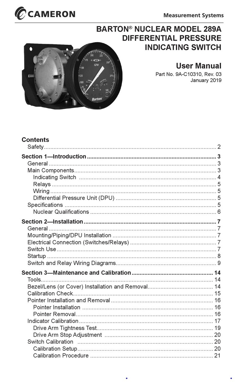
Cameron BARTON 289A User manual

Cameron
Cameron Scanner 2000 microEFM Instructions for use

Cameron
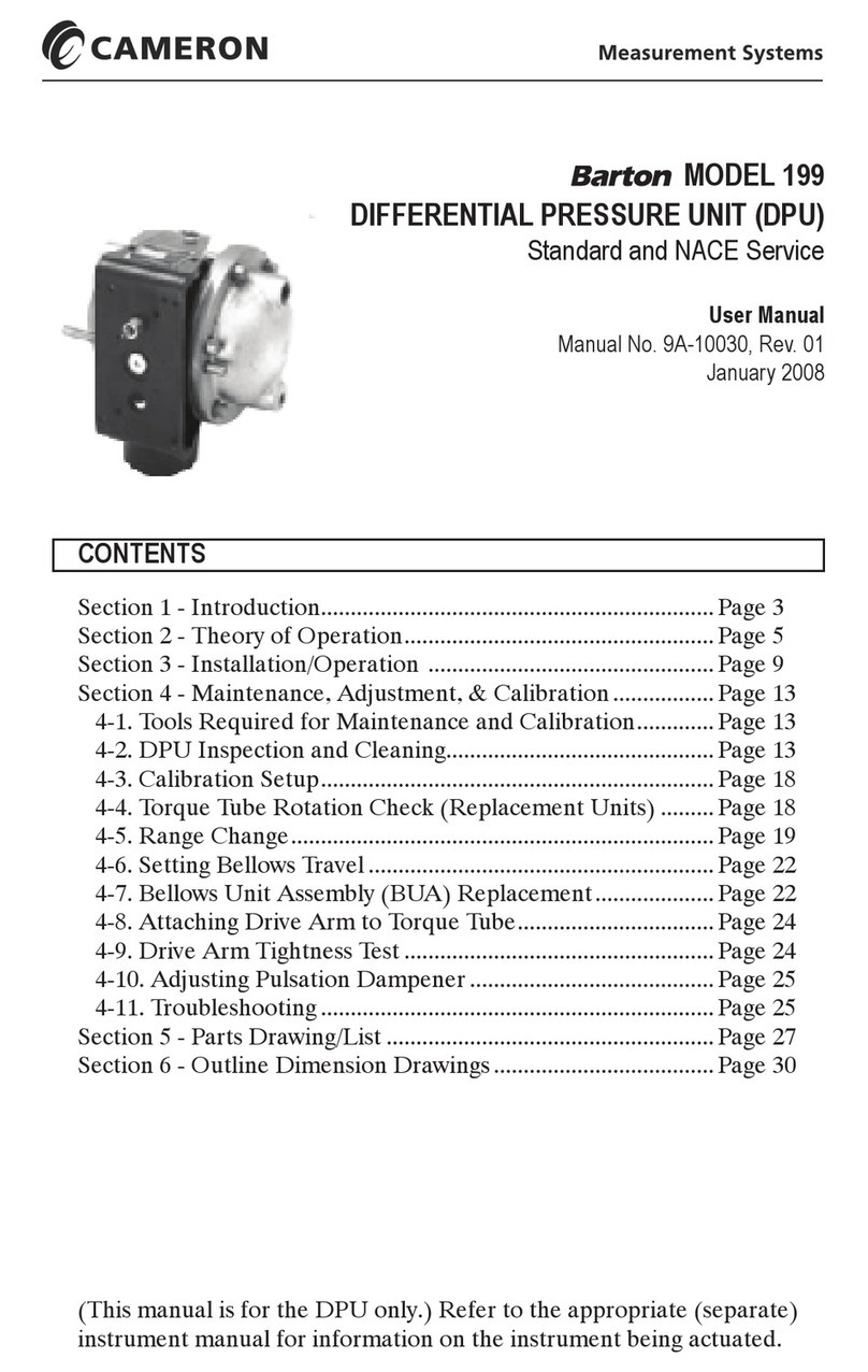
Cameron Barton 199 User manual

Cameron
Cameron LEFM 200 User manual

Cameron
Cameron NUFLO EZ-IN Series User manual

Cameron
Cameron NUFLO MC-III User manual

Cameron
Cameron NUFLO MC-III EXP User manual

Cameron
Cameron Scanner 3100 User manual

Cameron
Cameron Scanner 3100 EFM User manual

Cameron
Cameron NUFLO 1141C User manual