iv
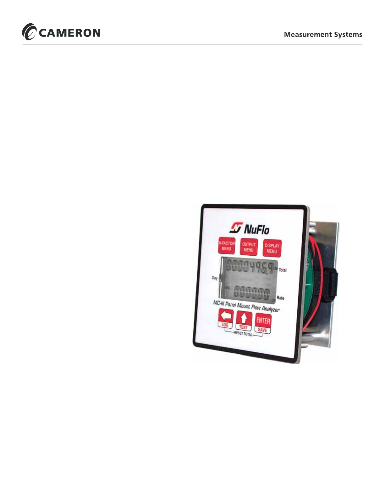
Table of Contents MC-III™ Panel Mount Flow Analyzer
Entering the Baud Rate .................................................................................................................................... 35
Section 4—Conguration and Operation via Software............................................................................... 37
Installing the Software ...................................................................................................................................... 37
Accessing Help ................................................................................................................................................. 37
Connecting to the Software .............................................................................................................................. 38
Automating Functions on Software Startup ............................................................................................... 39
Changing Autorun Settings ........................................................................................................................ 40
Express Connect Option ............................................................................................................................ 40
Changing the Communications Port .......................................................................................................... 41
Software Connection in Multi-Device Network ........................................................................................... 41
Setting Log Download Preferences .................................................................................................................. 43
Conguring the MC-III Panel Mount ................................................................................................................. 44
Conguration Wizard ................................................................................................................................. 46
Table 4.1—Menus for Conguring Parameters .......................................................................................... 47
MC-III Main Screen .................................................................................................................................... 48
Buttons and Tools....................................................................................................................................... 49
System Setup ................................................................................................................................................... 52
Time/Date Synchronization ....................................................................................................................... 52
Contract Hour ............................................................................................................................................. 52
LCD Contrast Adjustment .......................................................................................................................... 52
Security Setup ............................................................................................................................................ 53
Firmware Version Number ......................................................................................................................... 53
Serial Number ............................................................................................................................................ 53
Communications Port ....................................................................................................................................... 54
Slave Address ............................................................................................................................................ 54
Baud Rate ................................................................................................................................................. 54
Bus Delay ................................................................................................................................................... 55
Bus Timeout ............................................................................................................................................... 55
Software Communication Options ............................................................................................................. 55
Wellsite Information .......................................................................................................................................... 56
Turbine Input .................................................................................................................................................... 57
Volume Display .......................................................................................................................................... 57
Rate Display ............................................................................................................................................... 57
Input Type/Sensitivity Conguration ........................................................................................................... 58
Cut-Off Thresholds ..................................................................................................................................... 58
Calculation Period ...................................................................................................................................... 58
K-Factor Entry .................................................................................................................................................. 59
K-Factor Units ............................................................................................................................................ 59
K-Factor Type............................................................................................................................................. 59
K-Factor Backup ........................................................................................................................................ 60
Gas Volume Correction (Supercompressibility Calculation) ...................................................................... 61
4-20 mA Output ................................................................................................................................................ 63
Enabling 4-20 mA Output .......................................................................................................................... 65
4-20 mA Output Testing.............................................................................................................................. 65
Pulse Output ..................................................................................................................................................... 67
Conguring Pulse Output ........................................................................................................................... 67
Pulse Output Testing .................................................................................................................................. 68
Saving and Uploading Conguration Files ....................................................................................................... 69
Saving a Conguration File ........................................................................................................................ 69
Uploading a Conguration File ................................................................................................................... 70
Advanced Access ............................................................................................................................................ 72