Camille Bauer SIRAX BT7000 User manual

BETRIEBSANLEITUNG
AC/DC Stromwandler mit Messumformer-Funktionalität
SIRAX BT7000 / BT7050
Operating manual
AC/DC Current transformer with transmitter functionality
SIRAX BT7000 / BT7050
Camille Bauer Metrawatt AG
Aargauerstrasse 7
CH-5610 Wohlen/Schweiz
Tel: +41 56 618 21 11
Fax: +41 56 618 21 21
www.camillebauer.com

PM 1001931 000 00 Stromwandler für AC und DC SIRAX BT7000/BT7050 2/24
Inhaltsverzeichnis
1. Rechtliche Hinweise……………………………………………………………………………………………………… 3
1.1 Sicherheits und Warnhinweise …………………………………………………………………………………………… 3
1.2 Qualifiziertes Personal …………………………………………………………………………………………………… 3
1.3 Bestimmungsgemässer Gebrauch ………………………………………………………………………………………… 3
1.4 Haftungsausschluss ……………………………………………………………………………………………………… 3
1.5 Rückmeldung …………………………………………………………………………………………………………… 3
1.6 Reparaturen und Änderungen ……………………………………………………………………………………………… 3
1.7 Kalibration und Neuabgleich ……………………………………………………………………………………………… 3
1.8 Entsorgung ……………………………………………………………………………………………………………… 4
1.9 Rücksendung …………………………………………………………………………………………………………… 4
2. Einleitung………………………………………………………………………………………………………………… 4
2.1 Bestimmung des Dokukments …………………………………………………………………………………………… 4
2.2 Lieferumfang …………………………………………………………………………………………………………… 4
2.3 Weitere Unterlagen ……………………………………………………………………………………………………… 4
3. Funktionsbeschreibung ………………………………………………………………………………………………… 4
4. Montage und Installation ………………………………………………………………………………………………… 4
5. Elektrische Anschlüsse ………………………………………………………………………………………………… 5
6. Technische Daten………………………………………………………………………………………………………… 6
7. Programmierung ………………………………………………………………………………………………………… 7
7.1 Programmierung SIRAX BT7050 …………………………………………………………………………………………… 7
7.2 Programmierung SIRAX BT7000 …………………………………………………………………………………………… 7
7.2.1 Programmierung über DIP-Switch………………………………………………………………………………………… 7
7.2.2 Programmierung über Software ………………………………………………………………………………………… 8
7.2.2.1 Konfiguration ………………………………………………………………………………………………………… 8
7.2.2.2 Modbus Adress-register ………………………………………………………………………………………………10
8. Kennzeichnung des Typenschildes ………………………………………………………………………………………11
9. Zeichenerklärung…………………………………………………………………………………………………………11
10. Masszeichnungen ………………………………………………………………………………………………………12

PM 1001931 000 00 Stromwandler für AC und DC SIRAX BT7000/BT7050 3/24
1. Rechtliche Hinweise
1.1 Sicherheits und Warnhinweise
In diesem Dokument werden Sicherheits- und Warnhinweise verwendet, welche zur persönlichen Sicherheit und vermeidung von Sachschäden
befolgt werden müssen.
1.2 Qualifiziertes Personal
Das in diesem Dokument beschriebene Produkt darf nur von Personal gehandhabt werden, welches für die jeweilige Aufgabenstellung qualifiziert
ist. Qualifiziertes Personal hat die Ausbildung und Erfahrung um Risiken und Gefährdungen im Umgang mit dem Produkt erkennen zu können. Es
ist in der Lage die enthaltenen Sicherheits- und Warnhinweise zu verstehen und zu befolgen.
1.3 Bestimmungsgemässer Gebrauch
Das in diesem Dokument beschriebene Produkt darf nur für den von uns beschriebenen Anwendungszweck eingesetzt werden. Die in den tech-
nischen Daten angegebenen maximalen Anschlusswerte und zulässigen Umgebungsbedingungen müssen dabei eingehalten werden. Für den
einwandfreien und sicheren Betrieb des Gerätes wird sachgemässer Transport und Lagerung sowie fachgerechte Lagerung, Montage, Installati-
on, Bedienung und Wartung vorausgesetzt.
1.4 Haftungsausschluss
Der Inhalt dieses Dokuments wurde auf Korrektheit geprüft. Es kann trotzdem Fehler oder Abweichungen enthalten, so dass wir für die Vollstän-
digkeit und Korrektheit keine Gewähr übernehmen. Dies gilt insbesondere auch für verschiedene Sprachversionen dieses Dokuments. Dieses
Dokument wird laufend überprüft und ergänzt. Erforderliche Korrekturen werden in nachfolgende Versionen übernommen und sind via unsere
Webpage www.camillebauer.com verfügbar.
1.5 Rückmeldung
Falls Sie Fehler in diesem Dokument feststellen oder erforderliche Informationen nicht vorhanden sind, melden Sie dies bitte via E-Mail an:
customer-support@camillebauer.com
1.6 Reparaturen und Änderungen
Reparatur und Änderungen dürfen ausschließlich vom Hersteller durchgeführt werden. Önen Sie das Gehäuse des Gerätes nicht. Falls irgend-
welche unbefugten Änderungen am Gerät vorgenommen werden, erlischt der Garantieanspruch. Für Geräte, die nicht im Werk geönet wurden,
kann keine Gewährleistung oder Garantie übernommen werden. Wir behalten uns das Recht vor, das Produkt für Verbesserungen zu verändern.
1.7 Kalibration und Neuabgleich
Jedes Gerät wird vor der Auslieferung abgeglichen und geprüft. Der Auslieferungszustand wird erfasst und in elektronischer Form abgelegt. Die
Messunsicherheit von Messgeräten kann sich während des Betriebs ändern, falls z.B. die spezifizierten Umgebungsbedingungen nicht eingehal-
ten werden.
Ein Nichtbeachten führt zu Tod oder schwerer Körperverletzung.
Ein Nichtbeachten kann zu Sach- oder Personenschäden führen.
Ein Nichtbeachten kann dazu führen, dass das Gerät nicht die erwartete Funktionalität erfüllt oder beschädigt wird.
Die Installation und Inbetriebnahme darf nur durch geschultes Personal erfolgen. Überprüfen Sie vor der Inbetriebnahme, dass:
- die maximalen Werte aller Anschlüsse nicht überschritten werden, siehe Kapitel "Technische Daten",
- die Anschlussleitungen nicht beschädigt und bei der Verdrahtung spannungsfrei sind
- Energierichtung und Phasenfolge stimmen.
Das Gerät muss ausser Betrieb gesetzt werden, wenn ein gefahrloser Betrieb (z.B. sichtbare Beschädigungen) nicht mehr möglich ist. Dabei
sind alle Anschlüsse abzuschalten. Das Gerät ist an unser Werk bzw. an eine durch uns autorisierte Servicestelle zu schicken.
Ein Önen des Gehäuses bzw. Eingri in das Gerät ist verboten. Das Gerät hat keinen eigenen Netzschalter. Achten Sie darauf, dass beim
Einbau ein gekennzeichneter Schalter in der Installation vorhanden ist und dieser vom Benutzer leicht erreicht werden kann.
Bei einem Eingri in das Gerät erlischt der Garantieanspruch.
Es ist zu beachten, dass die auf dem Typenschild angegebenen Daten eingehalten werden!
Es sind die landesüblichen Vorschriften bei der Installation und Auswahl des Materials der elektrischen Leitungen zu befolgen!
PM 1001931 000 00 Stromwandler für AC und DC SIRAX BT7000/BT7050 4/24
1.8 Entsorgung
Geräte dürfen nur fachgerecht entsorgt werden!
Die Entsorgung der Geräte und Bestandteile darf nur unter Einhaltung guter professioneller Praktiken und nationaler Vorschriften
entsorgt werden. Eine falsche Entsorgung kann die Umwelt gefährden.
1.9 Rücksendung
Alle an Camille Bauer Metrawatt AG gesandten Geräte müssen frei von allen gefährlichen Verunreinigungen sein (Säuren, Laugen, Lösungsmit-
teln, usw.). Benutzen Sie die Originalverpackung oder eine geeignete Transportverpackung zur Rücksendung des Geräts.
Beschädigung bei der Rücksendung
Für Schäden, die durch eine unsachgemäße Rücksendung hervorgerufen werden, wird keine Gewährleistung oder Garantie
übernommen.
2. Einleitung
2.1 Bestimmung des Dokuments
Dieses Dokument beschreibt die Stromwandler für AC und DC SIRAX BT7000 und BT7050. Es richtet sich an Installateure, Inbetriebsetzer,
Service- und Wartungspersonal.
Gültigkeitsbereich
Diese Betriebsanleitung ist für alle Varianten der Stromwandler für AC und DC SIRAX BT7000 und BT7050 gültig.
Vorkenntnisse
Allgemeine Kenntnisse der Elektrotechnik sind erforderlich. Für Montage und Anschluss wird die Kenntnis der landesüblichen Sicherheitsbestim-
mungen und Installationsnormen vorausgesetzt.
2.2 Lieferumfang
• Stromwandler für AC und DC SIRAX BT7000 oder BT7050 mit Montage-Set
• Sicherheitshinweise (de, en, fr, it, es, nl, cz)
2.3 Weitere Unterlagen
Folgende weitere Dokumente zum Gerät sind elektronisch via www.camillebauer.com verfügbar:
• Datenblatt (de, en)
• Sicherheitshinweise (de, en, fr, it, es, nl, cz)
• Betriebsanleitung (de, en)
• Flyer Stromwandler
3. Funktionsbeschreibung
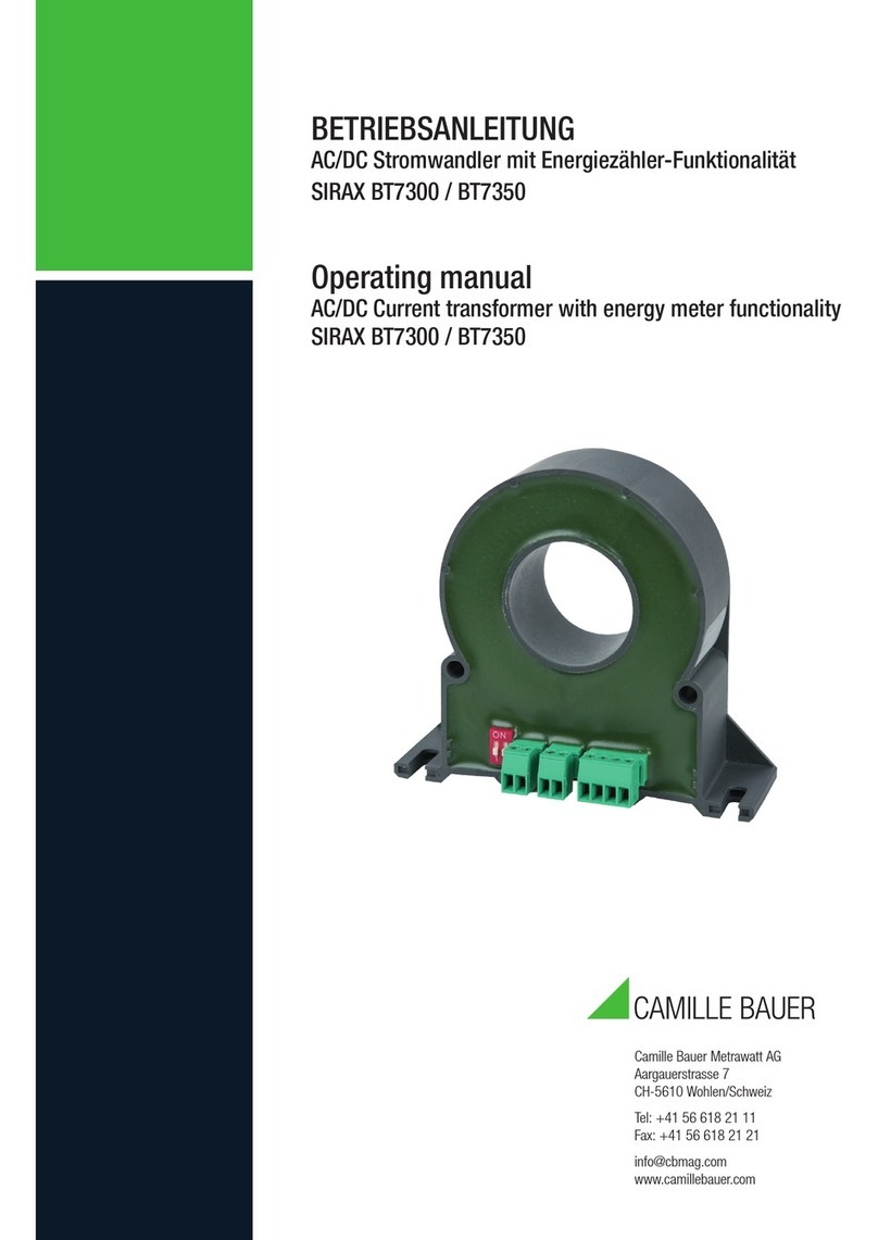
Der SIRAX BT7000 und BT7050 sind Stromwandler zur Überwachung von 1-phasigen AC- und DC-Systemen bis zu einem maximalen Strom von 50
A. Die Strommessung erfolgt galvanisch getrennt zur gemessenen Leitung. Die Geräte sind die ideale Lösung für Anwendungsfälle, bei denen der
Strom überwacht werden muss. Sie eignen sich perfekt zur Überwachung von mittleren/grossen Photovoltaik-Anlagen, Batterieladesystemen und
Industrieprozessen.
4. Montage und Installation
Sorgen Sie während der Montage, Installations- und Wartungsarbeiten für eine sichere Arbeitsumgebung. Unterbrechen Sie die
Stromzufuhr des Primärleiters und sichern Sie diese gegen unbeabsichtigtes Wiedereinschalten.
Magnetfelder mit hoher Intensität können die vom Transformator gemessenen Werte variieren. Vermeiden Sie die Installation in
der Nähe von Permanentmagneten, Elektromagneten oder Eisenmassen, die starke Veränderungen im Magnetfeld verursachen.
Wenn es Unregelmäßigkeiten gibt, empfehlen Sie, den Transformator in dem am besten geeigneten Bereich neu auszurichten
oder zu bewegen.
• Die Montage erfolgt über Schraubnuten für vertikale und horizontale Schalttafelmontage oder über Befestigungselemente für vertikale und
horizontale DIN-Hutschienenmontage.
• Die Einbaulage der Geräte ist beliebig.
• Schliessen Sie nun das Gerät gemäss Anschlussschema an.

PM 1001931 000 00 Stromwandler für AC und DC SIRAX BT7000/BT7050 5/24
Wenn Sie das Gerät in der horizontalen Lage
verwenden möchten, dann montieren Sie die
Befestigungselement wie auf dem Bild abge-
bildet durch Drücken in der Mitte des Clips.
Wenn Sie das Gerät in der vertikalen Lage
verwenden möchten, dann montieren Sie die
Befestigungselement wie auf dem Bild ab-
gebildet durch aufschieben der Haken in die
vorgesehenen Schlitze.
Für die horizontale Hutschienenmontage ha-
ken Sie zuerst die Unterseite ein und dann
drücken Sie mit beiden Händen wie auf dem
Bild abgebildet.
Für die senkrechte Hutschienenmontage ha-
ken Sie zuerst die Unterseite ein und dann
drücken Sie mit beiden Händen wie auf dem
Bild abgebildet.
Um die Geräte von der DIN-Hutschiene lösen zu können, verwenden Sie einen Schraubenzie-
her und hebeln Sie die Befestigungselemente nach oben wie auf den Bildern abgebildet. Die
Lamellen lösen sich von der Hutschiene.
5. Elektrische Anschlüsse
Achtung: Lebensgefahr! Sicherstellen, dass beim Anschluss alle Leitungen spannungsfrei sind !
Es ist zu beachten, dass die auf dem Typenschild angegebenen Daten eingehalten werden!
Es sind die landesüblichen Vorschriften bei der Installation und Auswahl des Materials der elektrischen Leitungen zu befolgen!
V
1 2
- +
11..30Vdc
V
RS485
USB
Anschlussschema BT7000Anschlussschema BT7050

PM 1001931 000 00 Stromwandler für AC und DC SIRAX BT7000/BT7050 6/24
6. Technische Daten
SIRAX BT7000 SIRAX BT7050
Eingang
Messtyp TRMS (monopolar)
Eingangsbereich
50 A AC/DC;
25 A AC/DC (über Dip-Switch);
bipolar (±50 A DC; ±25 A DC);
über RS485/Modbus RTU
50 A AC/DC;
25 A AC/DC (über Dip-Switch);
bipolar (±50 A DC; ±25 A DC)
Hilfsenergie 12 ... 30 V DC 11 ... 30 V DC
(Passiv loop powered)
Verbrauch max. 20 mA < 3.5 mA
Ausgang
Ausgangsbereich 0 ... 10 V
RS485 (Modbus RTU) 4 ... 20 mA
Reaktionszeit 1000 ms (Analogausgang)
30 ms (seriellen Ausgang) 1000 ms (Analogausgang)
Bandbreite bei -3dB DC oder 20 ... 2000 Hz
Genauigkeit
Genauigkeit 0.5% F.S.
Auflösung 12 Bit
Temperaturkoezient < 200 ppm/°C
Crest Faktor 2
Hysterese 0.15% F.S.
Umgebungsbedingungen
Umgebungstemperatur -15 ... +65 °C
Lagertemperatur -40 ... +85 °C
Relative Feuchte 10 ... 90 % (ohne Betauung)
Einsatzhöhe max. 2000 m
Sicherheit
Isolation 3 kV auf blankem Draht
Überspannung 2000 A (Puls); 300 A (kontinuierlich)
Gehäuseschutzart IP IP20
Mechanische Eigenschaften
Gehäusematerial PTB
Vergussmasse Epoxy Resins
Brennbarkeitsklasse UL94 V-0, selbstverlöschend, nicht tropfend, halogenfrei
Gewicht 72 g
DIP Switch 8 Pol 2 Pol
LED Permanent Gelb (Power ON)
Blinkend Gelb (Kommunikation) Permanent Gelb (Power ON)
Dimensionen 46.1 x 63 x 26.4 mm (ohne Klemmen)
Anschlüsse
Anschlüsse Steckklemmen 3.5 mm, 5 Pol Steckklemmen 3.5 mm, 2 Pol
Anschlussquerschnitt 1.5 mm2
Anzugsdrehmoment max. 0.25 Nm
Normen
Eingehaltene Normen EN61000-6-4; EN64000-6-2; EN61010-1

PM 1001931 000 00 Stromwandler für AC und DC SIRAX BT7000/BT7050 7/24
7. Programmierung
7.1 Programmierung SIRAX BT7050
Der SIRAX BT7050 hat zwei DIP-Schalter, durch die man die Skala
25 A oder 50 A stellen und zwischen monopolar oder bipolar wählen
kann (siehe DIP-Switch Tabelle). Die gelbe LED in der Nähe der Ste-
cker zeigt das Vorhandensein einer Energieversorgung an.
Wenn die bipolare Funktion für Wechselstrom verwendet wird, dann
beträgt der gelesene Werr 0 A (12 mA), da der Durchschnittswert
gelesen wird.
Jegliche Änderungen durch den DIP-Schalter machen
das Abschalten der Stromversorgung erforderlich. Es
ist eine Sicherheitsbedingung, um jegliche Störung
auf dem Gerät zu verhindern.
DIP-Schalter Einstellungen BT7050
Beschreibung 1 2
Monopolar (TRMS) 0
Bipolar (Mittelwert) 1
50 A 0
25 A 1
7.2 Programmierung SIRAX BT7000
Der SIRAX BT7000 kann auf zwei verschiedene Arten programmiert werden. Zum einen über die DIP-Schalter und zum Anderen über die Pro-
grammiersoftware.
7.2.1 Programmierung über DIP-Switch
Über die DIP-Schalter lässt sich die Skala 25 A oder 50 A stellen,
zwischen monopolar oder bipolar wählen und die Modbus-Adresse
(bis max. 15 Adressen) einstellen. (siehe DIP-Switch Tabelle).
Wenn die bipolare Funktion für Wechselstrom verwendet wird, dann
beträgt der gelesene Werr 0 A (5 V), da der Durchschnittswert gelesen
wird.
Die DIP-Schalter Einstellung ist nicht aktiviert, wenn
einer der vier Ersten DIP-Schalter auf 0000 gestellt
ist, der Rest der DIP-Schalter ist dann deaktiviert.
Alle Einstellungen kommen vom EEPROM.
Jegliche Änderungen durch den DIP-Schalter ma-
chen das Abschalten der Stromversorgung erforder-
lich. Es ist eine Sicherheitsbedingung, um jegliche
Störung auf dem Gerät zu verhindern.
DIP-Schalter Einstellungen BT7000
Beschreibung 1 2 3 4 5 6 7 8
EEPROM Einstellung 0 0 0 0
ADD = 1 0 0 0 1
ADD = 2 0 0 1 0
ADD = 15 1 1 1 1
Baudrate 2400 0 0
Baudrate 9600 0 1
Baudrate 38400 1 0
Baudrate 57800 1 1
Monopolar (TRMS) 0
Bipolar (Mittelwert) 1
50 A 0
25 A 1
Input / Output Bipolar
Input
Output
A
mA
4
12
20
-50 A
-25 A
+50 A
+25 A
Input / Output
Input
Output
A
mA
4
20
0+50 A
+25 A
Beispiel:
Wenn Sie den Messbereich von 0...50 A auf 0...25 A einstellen möchten, stellen Sie den DIP-Schalter Nr. 8 auf ON und stellen Sie auch einen
der ersten vier DIP-Schalter auf ON (wenn Sie das nicht tun, werden weiterhin die EEPROM Einstellungen verwendet).
Wenn Sie von Monopolar auf Bipolar umstellen möchten, stellen Sie den DIP-Schalter Nr. 7 auf ON und stellen Sie auch einen der ersten vier
DIP-Schalter auf ON (wenn Sie das nicht tun, werden weiterhin die EEPROM Einstellungen verwendet).

PM 1001931 000 00 Stromwandler für AC und DC SIRAX BT7000/BT7050 8/24
7.2.2.1 Konfiguration
Starten Sie die Software mit der Datei SIRAX BT7000-BT7100_004_
v121.jar
Klicken Sie nun auf "WEITER" um in das Menüfenster Verbindung zu
gelangen.
In diesem Modus können Sie wählen, ob Sie das Gerät über eine
direkte Verbindung via RS485-USB, oder im Offline-Modus program-
mieren möchten.
Wählen Sie den Modus "Verbindung mit RS485 Anschluss", dann
gelangen Sie zum Menü "Einstellung DIP-Schalter"
Wählen Sie den Modus "Keine Verbindung (OFF-Line), dann gelangen
Sie DIREKT zum Menü "Konfiguration".
7.2.2 Programmierung über Software
Der SIRAX BT7000 lässt sich über die serielle RS485-USB Schnittstelle und der Programmiersoftware programmieren. Laden Sie sich die Pro-
grammiersoftware kostenlos von unserer Homepage www.camillebauer.com herunter.
Bevor Sie die Software verwenden können, kontrollieren Sie, ob Sie Java (32-Bit) auf Ihrem Rechner installiert haben. Wenn nicht, dann laden Sie
die Java Software von der Hompage www.java.com herunter.
Um die Menüsprache der Software ändern zu können, gehen Sie in das heruntergeladene Verzeichnis der Software. Önen Sie das File "004.
ini" mit einem Text Editor Programm. Ändern Sie nun die aufgeführte Sprache z.B. "EN" in die gewünschte Sprache z.B. "DE". Bitte beachten Sie,
dass nur die im Verzeichnis aufgeführten Sprachen geändert werden können.
Input / Output Bipolar Input / Output
Output
OUT_START
IN_START
OUT_STOP
Input
A
IN_STOP
-50 A
10
5
-25 A
+50 A
+25 A
V
OUT_START
(Ex. 2 V)
OUT_STOP
(Ex. 8 V)
IN_START
(Ex. 10 A)
Input
Output
A
IN_STOP
(Ex. 40 A)
10
050 A
V

PM 1001931 000 00 Stromwandler für AC und DC SIRAX BT7000/BT7050 9/24
Stellen Sie die DIP-Schalter gemäss Vorlage ein. Genaue Angaben der
einzelnen Positionen der DIP-Schalter entnehmen Sie aus der Tabelle
"DIP-Schalter Einstellungen BT7000" auf Seite 7.
Drücken Sie auf "Weiter".
Um mit dem SIRAX BT7000 zu kommunizieren, überprüfen Sie den ver-
fügbaren COM PORT, indem Sie auf die Schaltfläche "AKTUALISIEREN"
klicken. Ihr PC wird eine virtuelle COM für die Kommunikation mit dem
SIRAX BT7000 zuweisen.
Klicken Sie auf den Button "VERBINDUNG MIT DEM GERÄT HERSTEL-
LEN", Sie sehen ein Fenster, in dem Sie gefragt werden, ob Sie mit
dem Gerät verbunden sind. Klicken Sie dann auf diesen Button in
diesem Fenster "WEITER". Nachdem Sie die Verbindung hergestellt
haben, können Sie mit der Konfiguration des Geräts auf den unten
beschriebenen Einstellungsseiten fortfahren.
Wählen Sie nun die Art der Konfigurationserstellung aus.
Konfigurieren Sie nun die gewünschten Parameter Ihres Gerätes.
Drücken Sie auf "Weiter".

PM 1001931 000 00 Stromwandler für AC und DC SIRAX BT7000/BT7050 10/24
7.2.2.2 Modbus Adress-Register
Modbus
Adresse Register Name Parameter Beschreibung Register-Typ Lesen /
Schreiben
Standard-
Werte Bereich
40001 Maschinen_ID Maschinen ID Unsigned 16 bits R 4
40002 FW_Version Firmware Version Unsigned 16 bits R
40003 Adresse Modbus Adresse Unsigned 16 bits R/W 1 1 ... 250
40004 Verzögerung Antwortverzögerung Unsigned 16 bits R/W 1 1 ... 1000
40005 Baudrate Baudrate:
0=1200 / 1=2400 / 2=4800 /
3=9600 / 4=19200 / 5=38400 /
6=57600 / 7=115200
Unsigned 16 bits R/W 1 0 ... 7
40006 Parität Typ Parität:
0=8, N, 1
1=8, O, 1 (ODD)
2=8, E, 1 (EVEN)
Unsigned 16 bits R/W 0 0 ... 2
40007 (LO)
40008 (HI)
In_Start Start Eingang (A) Floating 32 bits R/W 0
40009 (LO)
40010 (HI)
In_Stop Stop Eingang (A) Floating 32 bits R/W 50
40011 Out_Start_V Start Ausgang (mV) Unsigned 16 bits R/W 0 0 ... 10000
40012 Out_Stop_V Stop Ausgang (mV) Unsigned 16 bits R/W 10000 0 ... 10000
40013 filt 1 Unsigned 16 bits R/W 1 1 ... 32
40014 filt Unsigned 16 bits R/W 4096 1000 ... 20000
Wählen sie nun ob Sie die Konfiguration in einem File speichern, oder
diese an das Gerät übermitteln möchten.
Mit dieser Anzeige können Sie die Funktionalität des Geräte überprü-
fen.

PM 1001931 000 00 Stromwandler für AC und DC SIRAX BT7000/BT7050 11/24
40029 Unterdrückung Grenzwert (mA) Unsigned 16 bits R/W 250
40037 (LO)
40038 (HI)
RMS_A RMS Stromwert (A) Floating 32 bits R
40040 Befehl 0xC1C0: speichern Flash-Einstellungen
0xC1A0: Zurücksetzten Software
Unsigned 16 bits R/W
40048 Status Status Register:
Bit 0 = 1: Fehler Flash-Einstellungen
Bit 1 = 1: Fehler Flash-Kalibrierung
Bit 2 = 1: Überbereich
Bit 3 = 1: Unterbereich
Unsigned 16 bits R
40050 RMS_100 RMS Stromwert (Ax100) Unsigned 16 bits R
40051 (LO)
40052 (HI)
RMS_sw RMS Stromwert (A) getauscht Floating 32 bits R
40053 (LO)
40054 (HI)
Ah Zähler Ah (zurücksetzbar) Floating 32 bits R/W
40055 A_Max Max. Stromwert / 100 (zurücksetzbar) Unsigned 16 bits R/W
40056 A_Min Min. Stromwert / 100 (zurücksetzbar) Unsigned 16 bits R/W
40057 Data High Kalibrierdaten (Jahr, Monate) Unsigned 16 bits R
40058 Data Medium Kalibrierdaten (Tag, Stunden) Unsigned 16 bits R
40059 Data Low Kalibrierdaten (Minuten, Sekunden) Unsigned 16 bits R
8. Kennzeichnung der Typenschilder
SIRAX BT7000
Article-No.: 179938
20161118105725
M. ID: 25FW: 001HW: 04
SIRAX BT7050
Article-No.: 179946
20161118105725
M. ID: 25FW: 001HW: 04
Camille Bauer Metrawatt AG
Aargauerstrasse 7
5610 Wohlen / Switzerland
9. Zeichenerklärung
Symbol Bedeutung
Geräte dürfen nur fachgerecht entsorgt werden!
CE-Konformitätszeichen. Das Gerät erfüllt die Bedingungen der zutreenden EG-Richtlinien. Siehe Konformitätserklärung.
Achtung! Allgemeine Gefahrenstelle. Betriebsanleitung beachten.
Achtung: Lebensgefahr!
Bitte beachten

PM 1001931 000 00 Stromwandler für AC und DC SIRAX BT7000/BT7050 12/24
Bipolar
25 A
ON
1 2
21
- +
11..30Vdc
TRMS AC/DC
current transformer
50A
35.00
15.00
46.10
63.00
SIRAX BT7050
10. Dimensionen
35.00
15.00
46.10
63.00
SIRAX BT7000

PM 1001931 000 00 Current transformer for AC and DC SIRAX BT7000/BT7050 13/24
Table of Contents
1. Legal information…………………………………………………………………………………………………………14
1.1 Safety and warning notices…………………………………………………………………………………………………14
1.2 Qualified personal …………………………………………………………………………………………………………14
1.3 Intended use………………………………………………………………………………………………………………14
1.4 Disclaimer of liability ………………………………………………………………………………………………………14
1.5 Feedback …………………………………………………………………………………………………………………14
1.6 Repair work and modifications ……………………………………………………………………………………………14
1.7 Calibration and new adjustment ……………………………………………………………………………………………14
1.8 Disposal …………………………………………………………………………………………………………………15
1.9 Return ……………………………………………………………………………………………………………………15
2. Introduction ………………………………………………………………………………………………………………15
2.1 Purpose of this document …………………………………………………………………………………………………15
2.2 Scope of supply …………………………………………………………………………………………………………15
2.3 Further documents ………………………………………………………………………………………………………15
3. Functional description ……………………………………………………………………………………………………15
4. Assembly and installation ………………………………………………………………………………………………15
5. Electrical connections ……………………………………………………………………………………………………16
6. Technical specifications …………………………………………………………………………………………………17
7. Programming ……………………………………………………………………………………………………………18
7.1 Programming SIRAX BT7050 ………………………………………………………………………………………………18
7.2 Programming SIRAX BT7000 ………………………………………………………………………………………………18
7.2.1 Programming over DIP-switch ……………………………………………………………………………………………18
7.2.2 Programming over software………………………………………………………………………………………………19
7.2.2.1 Conficuration …………………………………………………………………………………………………………19
7.2.2.2 Modbus Adress-Register ………………………………………………………………………………………………21
8. Identification of the type label ……………………………………………………………………………………………22
9. Sign explanation …………………………………………………………………………………………………………22
10. Dimensions drawings……………………………………………………………………………………………………23

PM 1001931 000 00 Current transformer for AC and DC SIRAX BT7000/BT7050 14/24
1. Legal information
1.1 Safety and warning notices
In this document safety and warning notices are used, which you have to observe to ensure personal safety and to prevent damage to property.
1.2 Qualified personnel
The product described in this document may be handled by personnel only, which is qualified for the respective task. Qualified personnel have
the training and experience to identify risks and potential hazards when working with the product. Qualified personnel are also able to understand
and follow the given safety and warning notices.
1.3 Intended use
The product described in this document may be used only for the application specified. The maximum electrical supply data and ambient con-
ditions specified in the technical data section must be adhered. For the perfect and safe operation of the device proper transport and storage as
well as professional assembly, installation, handling and maintenance are required.
1.4 Disclaimer of liability
The content of this document has been reviewed to ensure correctness. Nevertheless it may contain errors or inconsistencies and we cannot
guarantee completeness and correctness. This is especially true for dierent language versions of this document. This document is regularly
reviewed and updated. Necessary corrections will be included in subsequent version and are available via our webpage www.camillebauer.com.
1.5 Feedback
If you detect errors in this document or if there is necessary information missing, please inform us via e-mail to:
customer-support@camillebauer.com
1.6 Repair work and modifications
Repair work and modifications shall exclusively be carried out by the manufacturer. Do not open the housing of the device. In case of any tampe-
ring with the device, the guaranty claim shall lapse. We reserve the right of changing the product to improve it.
1.7 Calibration and new adjustment
Each device is adjusted and checked before delivery. The condition as supplied to the customer is measured and stored in electronic form.
The uncertainty of measurement devices may be altered during normal operation if, for example, the specified ambient conditions are not met.
If the warning notice is not followed death or severe personal injury will result.
If the warning notice is not followed damage to property or severe personal injury may result.
If the warning notice is not followed the device may be damaged or may not fulfill the expected functionality.
The installation and commissioning should only be carried out by trained personnel.
Check the following points before commissioning:
- that the maximum values for all the connections are not exceeded, see „Technical data“ section,
- that the connection wires are not damaged, and that they are not live during wiring,
- that the power flow direction and the phase rotation are correct.
The instrument must be taken out of service if safe operation is no longer possible (e.g. visible damage). In this case, all the connections must
be switched o. The instrument must be returned to the factory or to an authorized service dealer.
It is forbidden to open the housing and to make modifications to the instrument. The instrument is not equipped with an integrated circuit brea-
ker. During installation check that a labeled switch is installed and that it can easily be reached by the operators.
Unauthorized repair or alteration of the unit invalidates the warranty.
Please observe that the data on the type plate must be adhered to!
The national provisions have to be observed in the installation and material selection of electric lines!

PM 1001931 000 00 Current transformer for AC and DC SIRAX BT7000/BT7050 15/24
1.8 Disposal
Device may only be disposed in a professional manner!
The disposal of devices and components may only be realised in accordance with good professional practice observing the
country-specifi c regulations. Incorrect disposal can cause environmental risks.
1.9 Return
All devices delivered to Camille Bauer Metrawatt AG shall be free of any hazardous contaminants (acids, lyes, solutions, etc.).
Use original packaging or suitable transport packaging to return the device.
Damage by returning
Damages caused by improper returning, no warranties or guarantees can be given.
2. Introduction
2.1 Purpose of this document
This document describes the current transformer SIRAX BT7000 and BT7050. It is intended to be used by Installation personnel, commissioning
engineers, Service and maintenance personnel.
Scope
This handbook is valid for all versions of the current transformer SIRAX BT7000 and BT7050. Some of the functions described in this document
are available only, if the necessary optional components are included in the device.
Required knowledge
A general knowledge in the field of electrical engineering is required. For assembly and installation of the device knowledge of applicable national
safety regulations and installation standard is required.
2.2 Scope of supply
• Current transformer SIRAX BT7000 or BT7050 with Connection set
• Safety instructions (ge, en, fr, it, es, nl, cz)
2.3 Further documents
The following documents are provided electronically via www.camillebauer.com:
• Datasheet (ge, en)
• Safety instructions (ge, en, fr, it, es, nl, cz)
• Operating manual (ge, en)
• Flyer current transformer program
3. Functional description
The SIRAX BT7000 and BT7050 are current transformers for monitoring 1-phase AC and DC systems up to a maximum current of 50 A. The
current measurement is galvanically separated from the measured line. The devices are the ideal solution for applications where power needs to be
monitored. They are perfect for monitoring medium / large photovoltaic systems, battery charging systems and industrial processes.
4. Assembly and installation
Ensure a safe working environment during assembly, installation and maintenance work. Disconnect the power supply of the
primary conductor and secure it against unintentional reconnection.
Magnetic fields of high intensity can vary the values measured by the transformer. Avoid installation near permanent magnets,
electromagnets or iron masses that induce strong changes in the magnetic field. If there are any irregularities, we recommend
realigning or moving the transformer in the most appropriate area.
• Mounting is via screw grooves for vertical and horizontal panel mounting or via fastening elements for vertical and horizontal DIN rail moun-
ting.
• The installation of the devices is arbitrary.
• Now connect the device according to the wiring diagram.

PM 1001931 000 00 Current transformer for AC and DC SIRAX BT7000/BT7050 16/24
If you want to use the device in a horizontal
position, mount the hook as shown in the pic-
ture by pressing the center of the clip.
If you want to use the device in the vertical
position, then assemble the hook as shown
in the picture by sliding them into the slots
provided.
For horizontal DIN rail mounting, first hook in
the bottom and then press with both hands as
shown in the picture.
For vertical DIN rail mounting, first hook in the
underside and then press with both hands as
shown in the picture.
In order to be able to detach the devices from the DIN rail, use a screwdriver and pry up the
fastening elements as shown in the pictures. The slats detach from the DIN rail.
5. Electrical connections
Attention: danger to life! Ensure under all circumstances that the leads are free of potential when connecting them!
It is to be noted, that the data given on the type plate are respected!
The national regulations for the installation and selection of the material of the electrical cables must be followed!
V
1 2
- +
11..30Vdc
V
RS485
USB
Connection scheme BT7000Connection scheme BT7050

PM 1001931 000 00 Current transformer for AC and DC SIRAX BT7000/BT7050 17/24
6. Technical specifications
SIRAX BT7000 SIRAX BT7050
Input
Type of measure TRMS (monopolar)
Input range
50 A AC/DC;
25 A AC/DC (over Dip switch);
bipolar (±50 A DC; ±25 A DC);
over RS485/Modbus RTU
50 A AC/DC;
25 A AC/DC (over Dip switch);
bipolar (±50 A DC; ±25 A DC)
Power supply 12 ... 30 V DC 11 ... 30 V DC
(Passive loop powered)
Absorption max 20 mA < 3.5 mA
Output
Output range 0 ... 10 V
RS485 (Modbus RTU) 4 ... 20 mA
Response time 1000 ms (analog output)
30 ms (serial output) 1000 ms (analog output)
Band width at -3dB DC or 20 ... 2000 Hz
Accuracy
Accuracy 0.5% F.S.
Resolution 12 Bit
Temperature coecient < 200 ppm/°C
Crest factor 2
Hysteresis 0.15% F.S.
Environmental conditions
Working temperature -15 ... +65 °C
Storage temperature -40 ... +85 °C
Humidity 10 ... 90 % (not condensing)
Altitude max 2000 m
Safety
Isolation 3 kV on bare wire
Overload 2000 A (pulse); 300 A (continuos)
Protection class IP20
Mechanical properties
Housing material PTB
Filling Epoxy Resins
Flammability UL94 V-0, self-extinguishing, non-dripping, halogen-free
Weight 72 g
DIP switch 8 pole 2 pole
LED Permanent yellow (Power ON)
Blinking yellow (communication) Permanent yellow (Power ON)
Dimensions 46.1 x 63 x 26.4 mm (without terminals)
Connections
Connections Plug-in terminals 3.5 mm, 5 Pol Plug-in terminals 3.5 mm, 2 Pol
Cross-sectional area 1.5 mm2
Torque max 0.25 Nm
Standards
Adhered standards EN61000-6-4; EN64000-6-2; EN61010-1

PM 1001931 000 00 Current transformer for AC and DC SIRAX BT7000/BT7050 18/24
7. Programming
7.1 Programming SIRAX BT7050
The SIRAX BT7050 has two DIP switches that allow you to set the
25 A or 50 A scale and choose between monopolar or bipolar (see
DIP switch table). The yellow LED near the connector indicates the
presence of a power supply.
When the AC bipolar function is used, the read value is 0 A (12 mA)
since the average value is read.
Any changes made by dip-switch required to switch
o the power supply. It’s a safety condition in order to
prevent any manumission on the device.
DIP-switsch settings BT7050
Description 1 2
Monopolar (TRMS) 0
Bipolar (Mean Value) 1
50 A 0
25 A 1
Input / Output Bipolar
Input
Output
A
mA
4
12
20
-50 A
-25 A
+50 A
+25 A
Input / Output
Input
Output
A
mA
4
20
0+50 A
+25 A
7.2 Programming SIRAX BT7000
The SIRAX BT7000 can be programmed in two dierent ways. On the one hand via the DIP switches and on the other hand via the programming
software.
7.2.1 Programming over DIP-switch
The DIP switches can be used to set the 25 A or 50 A scale, choose
between monopolar or bipolar and set the Modbus address (up to a
maximum of 15 addresses). (see DIP switch table).
When the AC bipolar function is used, the read value is 0 A (5 V) since
the average value is read.
The setting is not enabled if the first fourth dip-swit-
ches are set to 0000, the rest of dip-switch are
disabled. All settings coming from EEPROM.
Any changes made by dip-switch required to switch
o the power supply. It’s a safety condition in order
to prevent any manumission on the device.
DIP-switsch settings BT7000
Description 1 2 3 4 5 6 7 8
EEPROM settings 0 0 0 0
ADD = 1 0 0 0 1
ADD = 2 0 0 1 0
ADD = 15 1 1 1 1
Baudrate 2400 0 0
Baudrate 9600 0 1
Baudrate 38400 1 0
Baudrate 57800 1 1
Monopolar (TRMS) 0
Bipolar (Mean Value) 1
50 A 0
25 A 1
Example:
If you want to set the measure range from 0...50 A to 0... 25A, please, put ON the dip-switch n°8 and put ON also one of the first four dip-switch
(if you don’t do that it continue to take the EEPROM setting).
If you want to modify from Monopolar (default) to Bipolar function by dip-switch, please, put ON the dip n°7 and put ON also one of the first dip-
switch (if you don’t do that it continue to take the EEPROM setting).

PM 1001931 000 00 Current transformer for AC and DC SIRAX BT7000/BT7050 19/24
Input / Output Bipolar Input / Output
Output
OUT_START
IN_START
OUT_STOP
Input
A
IN_STOP
-50 A
10
5
-25 A
+50 A
+25 A
V
OUT_START
(Ex. 2 V)
OUT_STOP
(Ex. 8 V)
IN_START
(Ex. 10 A)
Input
Output
A
IN_STOP
(Ex. 40 A)
10
050 A
V
7.2.2 Programming over Software
The SIRAX BT7000 can be programmed via the serial RS485-USB interface and the programming software. Download the programming software
for free from our homepage www.camillebauer.com.
Before you can use the software, check if you have Java (32-bit) installed on your computer. If not, download the Java software from the home-
page www.java.com.
To change the menu language of the software, go to the downloaded directory of the software. Open the file "004.ini" with a text editor program.
Now change the listed language, e.g. "EN" in the desired language e.g. "DE". Please note that only the languages listed in the directory can be
changed.
7.2.2.1 Configuration
Start the software with the file SIRAX BT7000-BT7100_004_v121.jar
Now click on "NEXT" to get into the menu window Connection.
In this mode, you can choose to program the device via a direct
connection via RS485-USB, or in offline mode.
Select the mode "Connection with RS485 connection", then you get to
the menu "DIP switch setting"
If you select the mode "no connection (OFF-Line)", then you arrive
DIRECTLY to the menu "configuration".

PM 1001931 000 00 Current transformer for AC and DC SIRAX BT7000/BT7050 20/24
Set the DIP switches according to the template. Detailed information
on the individual positions of the DIP switches can be found in the
table "DIP switch settings BT7000" on page 7.
Press "Next".
To communicate with the SIRAX BT7000, check the available COM
PORT by clicking on the "UPDATE" button. Your PC will assign a virtual
COM for communication with the SIRAX BT7000.
Click the "CONNECT TO THE DEVICE" button, you will see a window
asking if you are connected to the device. Then click on this button in
this window "CONTINUE". After you have established the connection,
you can proceed with the configuration of the device on the setting
pages described below.
Now select the type of configuration creation.
Now configure the desired parameters of your device.
Press "Next".
This manual suits for next models
3
Table of contents
Languages:
Other Camille Bauer Transformer manuals

Camille Bauer
Camille Bauer SIRAX BT7200 User manual

Camille Bauer
Camille Bauer SIRAX CT3 Series User manual

Camille Bauer
Camille Bauer SIRAX Series Installation instructions

Camille Bauer
Camille Bauer SIRAX BT7300 Installation instructions

Camille Bauer
Camille Bauer SIRAX CT6 Series User manual

Camille Bauer
Camille Bauer SIRAX BT7300 User manual