manuals.online logo
Brands
  1. Home
  2. •
  3. Brands
  4. •
  5. Camoplast
  6. •
  7. Offroad Vehicle
  8. •
  9. Camoplast Tatou UTV T4S Instruction sheet

Camoplast Tatou UTV T4S Instruction sheet

Other manuals for Tatou UTV T4S

12

Other Camoplast Offroad Vehicle manuals

Camoplast ATV T4S Instruction sheet

Camoplast

Camoplast ATV T4S Instruction sheet

Camoplast ATV T4S Instruction sheet

Camoplast

Camoplast ATV T4S Instruction sheet

Camoplast Tatou UTV T4S Instruction sheet

Camoplast

Camoplast Tatou UTV T4S Instruction sheet

Camoplast ATV T4S Instruction sheet

Camoplast

Camoplast ATV T4S Instruction sheet

Camoplast Tatou UTV T4S Instruction sheet

Camoplast

Camoplast Tatou UTV T4S Instruction sheet

Camoplast Tatou UTV T4S Instruction sheet

Camoplast

Camoplast Tatou UTV T4S Instruction sheet

Camoplast Tatou UTV T4S Instruction sheet

Camoplast

Camoplast Tatou UTV T4S Instruction sheet

Camoplast Tatou UTV T4S Instruction sheet

Camoplast

Camoplast Tatou UTV T4S Instruction sheet

Camoplast ATV T4S Instruction sheet

Camoplast

Camoplast ATV T4S Instruction sheet

Camoplast 1099-01-1105 User manual

Camoplast

Camoplast 1099-01-1105 User manual

Popular Offroad Vehicle manuals by other brands

Polaris Sportsman 570 EFI owner's manual

Polaris

Polaris Sportsman 570 EFI owner's manual

Polaris RANGER XP 1000 EPS 2018 owner's manual

Polaris

Polaris RANGER XP 1000 EPS 2018 owner's manual

Yamaha Tri Moto 125 Service manual

Yamaha

Yamaha Tri Moto 125 Service manual

APRILIA QUASAR 100 manual

APRILIA

APRILIA QUASAR 100 manual

Yamaha YFM350X Warrior owner's manual

Yamaha

Yamaha YFM350X Warrior owner's manual

Polaris RZR 900 owner's manual

Polaris

Polaris RZR 900 owner's manual

Baja motorsports ATV 90 Setup instructions

Baja motorsports

Baja motorsports ATV 90 Setup instructions

Suzuki LT-A700X owner's manual

Suzuki

Suzuki LT-A700X owner's manual

Ski-Doo SCANDIC WT Operator's guide

Ski-Doo

Ski-Doo SCANDIC WT Operator's guide

Polaris Sportsman 550 XP EPS owner's manual

Polaris

Polaris Sportsman 550 XP EPS owner's manual

Arctic Cat 120 sno pro Operator's manual

Arctic Cat

Arctic Cat 120 sno pro Operator's manual

Yamaha RS90PB owner's manual

Yamaha

Yamaha RS90PB owner's manual

Arctic Cat ALTERRA 450 Service manual

Arctic Cat

Arctic Cat ALTERRA 450 Service manual

Dinli DL702 Service manual

Dinli

Dinli DL702 Service manual

Polaris RZR XP 1000 Service manual

Polaris

Polaris RZR XP 1000 Service manual

Polaris Sportsman 9922233 owner's manual

Polaris

Polaris Sportsman 9922233 owner's manual

Yamaha SXV70ML owner's manual

Yamaha

Yamaha SXV70ML owner's manual

Ski-Doo SKANDIC Operator's guide

Ski-Doo

Ski-Doo SKANDIC Operator's guide

manuals.online logo
manuals.online logoBrands
  • About & Mission
  • Contact us
  • Privacy Policy
  • Terms and Conditions

Copyright 2025 Manuals.Online. All Rights Reserved.

Installation Guidelines
Directives d’installation
Kawasaki
5000-04-0610-U4MAN
VERSION E
® and TM are trademarks of Camoplast Inc./® et Mc sont des marques de Camoplast Solideal inc.
All rights reserved./Tous droits réservés. ©2015 Camoplast Solideal Inc
Printed in Canada/Imprimé au Canada
IMPORTANT
Please read carefully each part of this document as well as the User Manual prior to assembling,
installing and using the track system.
Veuillez lire attentivement ce document, en entier, ainsi que le Manuel de lutilisateur avant
dassembler, dinstaller et dutiliser le système de traction.
Page3
Installation Guidelines / Directives d’installation
FRONT ANCHOR BRACKET PARTS LIST / LISTE DE PIÈCES - ANCRAGE AVANT
Figure 1


























ITEM P/N DESCRIPTION QTY
1 1004-04-0610 FRONT BRACKET KIT / ENSEMBLE ANCRAGE AVANT 1
2 1004-04-0610-ASS FRONT ANCHOR BRACKET / ANCRAGE AVANT 2
3 1006-02-0015-F FRONT BRACKET COVER / COUVERT ANCRAGE AVANT 2
4 1006-04-0018-F FRONT BRACKET COVER / COUVERT ANCRAGE AVANT 2
5 1033-08-0030 HEX BOLT / BOULON HEX - HCS, M8-1.25X30, 8.8, ZP, DIN931 2
6 1033-10-0065 HEX BOLT / BOULON HEX - HCS, M10-1.5X65, 8.8, ZP, DIN931 2
7 1071-08-0001 NYLON NUT / ÉCROU NYLON - NN, M8-1.25, 8, ZP, DIN985 2
8 1071-10-0001 NYLON NUT / ÉCROU NYLON - NN, M10-1.5, 8, ZP, DIN982 2
Page 4
©2015 Camoplast Solideal Inc.
REAR ANCHOR BRACKET PARTS LIST / LISTE DE PIÈCES - ANCRAGE ARRIÈRE
Figure 2
WHEEL LUG NUT / ÉCROU DE ROUE
Figure 3
Installation Guidelines / Directives d’installation

 

 




 

 



ITEM P/N DESCRIPTION QTY
9 1002-04-0610 REAR BRACKET KIT / ENSEMBLE ANCRAGE ARRIÈRE 1
10 1002-04-0610-ASS ANTI-ROTATION REAR BRACKET / ANCRAGE ANTIROTATION ARR. 1
11 1006-04-0610-F REAR BRACKET COVER / COUVERT ANCRAGE ARRIÈRE 1
12 1033-10-0065 HEX BOLT / BOULON HEX - HCS, M10-1.5X65, 8.8, ZP, DIN931 3
13 1071-10-0001 NYLON NUT / ÉCROU NYLON - NN, M10-1.5, 8, ZP, DIN982 3

ITEM P/N DESCRIPTION QTY
14 1178-10-X001 WHEEL LUG NUT / ÉCROU DE ROUE - LN, M10-1.25x20, 8, ZP 16
Page5
STABILIZING ROD / BRAS STABILISATEUR
Figure 4
Installation Guidelines / Directives d’installation

ITEM P/N DESCRIPTION QTY
15 1001-01-0102 STABILIZING ROD ASSY / BRAS STABILISATEUR ASSEMBLÉ 2
Page 6
©2015 Camoplast Solideal Inc.
VERIFICATION / VÉRIFICATION
CAUTION: Before beginning the installation,
make sure that you have received all the
components included in the parts lists of the
preceding pages.
ATTENTION : Avant de débuter l'installation,
assurez-vous d’avoir reçu toutes les
composantes incluses dans les listes de pièces
aux pages précédentes.
INFORMATION
1. For installation purposes, directional arrows have
been cut out of the main components in the anchor
bracket kits. These arrows indicate the front of the
vehicle relative to the component. See Figure 5.
1. Pour faciliter le positionnement des ancrages au
véhicule, des flèches indiquant l’avant du véhicule
ont été découpées aux composantes principales
des ancrages. Assurez-vous que ces flèches
pointent en direction de l’avant du véhicule lors de
l’assemblage de celles-ci. Voir la Figure 5.
Figure 5
Installation Guidelines / Directives d’installation
Page7
PREPARATION / PRÉPARATION
WARNING AVERTISSEMENT
Never place any part of your body under the
vehicle unless it is securely placed on appropriate
stands. Severe injuries could occur if the vehicle
collapses or moves. Do not use a lifting device as a
secure stand.
Ne jamais exposer des parties de votre corps
sous le véhicule à moins que celui-ci ne repose
sur des supports appropriés. Si le véhicule devait
capoter ou se déplacer, cela pourrait vous
occasionner des blessures graves. Ne pas
utiliser un dispositif de levage en guise de
support permanent.
1. Position the vehicle on a flat and level surface (or on
a suitable lifting device), shift the transmission to
neutral and turn off engine.
1. Placer le véhicule sur une surface plane et au
niveau (ou sur un dispositif de levage), mettre la
transmission au point mort et arrêter le moteur.
2. Identify and position each unit of the track system
near the position indicated on the sticker affixed on
the frame. Refer to Figure 6.
2. Identifier et placer chaque système de l’ensemble
de traction près de la position d’installation indiquée
sur l’étiquette apposée au châssis. Voir la Figure 6.
Figure 6
Installation Guidelines / Directives d’installation
Page 8
©2015 Camoplast Solideal Inc.
REAR TRACK SYSTEMS / SYSTÈMES DE TRACTION ARRIÈRE
1. Using a lifting device, raise the rear of the
vehicle and install appropriate stands. Ensure
that the vehicle is immobilized and safe to work
on.
1. Au moyen d’un dispositif de levage, soulever
l’arrière du véhicle et installer des cales de
sûreté. Assurez-vous que le véhicule est bien
immobile et qu’on peut y travailler en sécurité
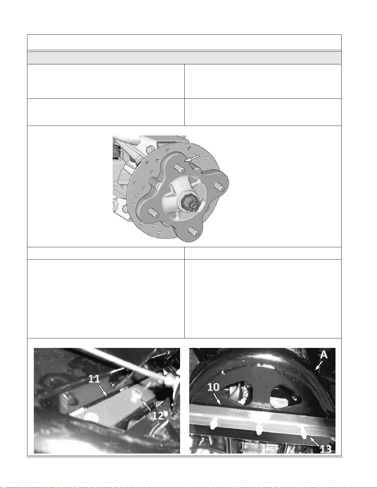
2. Remove rear wheels. Make sure that wheel
studs and wheel hubs are free of dirt. See
Figure 7.
2. Enlever les roues arrière. Assurez-vous que les
goujons de roue et les moyeux de roue sont
exempts de toute saleté. Voir la Figure 7.
Figure 7
3. If applicable, remove CV joint protectors.
3. Retirer, au besoin, les protecteurs de joint homocinétique.
4. Position the rear bracket cover (11) above the
rear frame (A). Align holes in cover with existing
holes in frame and insert the M10 bolts (12).
From underneath, bring the rear anchor bracket
(10) up to the M10 bolts just inserted, align holes
in bracket with bolts and install bracket over the
bolts. The anchor bracket’s end plates must be
positioned towards the rear of the vehicle. Install
the nuts (13) supplied and tighten the bolts to 50
N•m [37 lb-ft] of torque. See Figure 8.
4. Positionner le couvert (11) de l'ancrage arrière
au-dessus du châssis arrière (A). Aligner les
trous du couvert aux trous existant du châssis et
insérer les boulons (12) aux trous. Positionner
l'ancrage arrière (10) aux boulons
préalablement insérés, les oreilles de l'extrémité
du tube doivent être en direction de l'arrière du
véhicule. Installer les écrous (13) fournis et
serrer les boulons à un couple de 50 N•m [37
lb–ft]. Voir la Figure 8.
Figure 8
Installation Guidelines / Directives d’installation
Page9
5. Attach the rear suspension stabilizing rod (15) to
the undercarriage bracket using the washers
(A), bushing (B) and nut (C). See Figure 9.
5. Fixer le bras stabilisateur (15) au trou de la
pièce d’ancrage du système de traction au
moyen des rondelles (A), d’un espaceur (B) et
d’un écrou (C). Voir la Figure 9.
Figure 9
6. Secure the undercarriage to the rear hub using
the wheel nuts (14) provided in the installation
kit. Refer to Figure 10.
NOTE: If needed, take rubber protector off of hub.
NOTE: Ensure that the cotter pin of the axle nut
does not interfere with the undercarriage
hub.
NOTE: Follow the torque specification indicated by
the vehicle’s manufacturer when tightening
wheel nuts.
6. Fixer le système de traction au moyeu de roue
arrière. Utiliser les écrous de roue (14) fournis
dans l’ensemble d’installation. Voir la Figure 10.
NOTE : Retirer le protecteur en caoutchouc du
moyeu, s’il y a lieu.
NOTE : Assurez-vous que la goupille fendue de
l’écrou de l’essieu n’interfère pas au
coeur du moyeu du système de traction.
NOTE : Serrer les écrous de roue au couple de
indiqué par le fabricant du véhicule.
Figure 10
Installation Guidelines / Directives d’installation
Page 10
©2015 Camoplast Solideal Inc.
CAUTION: Orientation of the bolt (C) which
secures the stabilizing rod in place is crucial.
Wrong orientation can cause breakage on
track systems and vehicle components.
7. Attach the rear suspension stabilizing rod (A) to
the rear anchor bracket end plate (B) using the
bolt (C), bushing (D), washer (E) and nut (F).
Tighten to 50 N•m [37 lb•ft]. Refer to Figure 11.
NOTE: Ensure that parts are assembled in the
correct order.
ATTENTION : L’orientation des boulons (C)
qui retiennent les bras stabilisateurs est
cruciale. Une mauvaise orientation peut
entraîner des bris aux systèmes et aux
composantes du véhicule.
7. Fixer le bras stabilisateur (A) au point de fixation
de l’ancrage arrière (B) au moyen du boulon (C),
de l’espaceur (D), de la rondelle (E) et de l’écrou
(F). Serrer à un couple de 50 N•m [37 lb•pi]. Voir
la Figure 11.
NOTE : Assurez-vous d’assembler les pièces dans
l’ordre indiqué.
Figure 11
8. Inspect the rear track systems and ensure that
all assembly bolts were correctly tightened
during installation. Lower the vehicle to the
ground and proceed to install the front track
systems.
8. Inspecter les systèmes de traction arrière et
s’assurer que tous les boulons ont été serrés
correctement lors de l’installation. Abaisser
ensuite le véhicule au sol et procéder à
l’installation des systèmes de traction avant.
Installation Guidelines / Directives d’installation