H
V
A
C
P
R
O
D
U
C
S
H
V
A
C
P
R
O
D
U
C
S
H
V
A
C
P
R
O
D
U
C
S
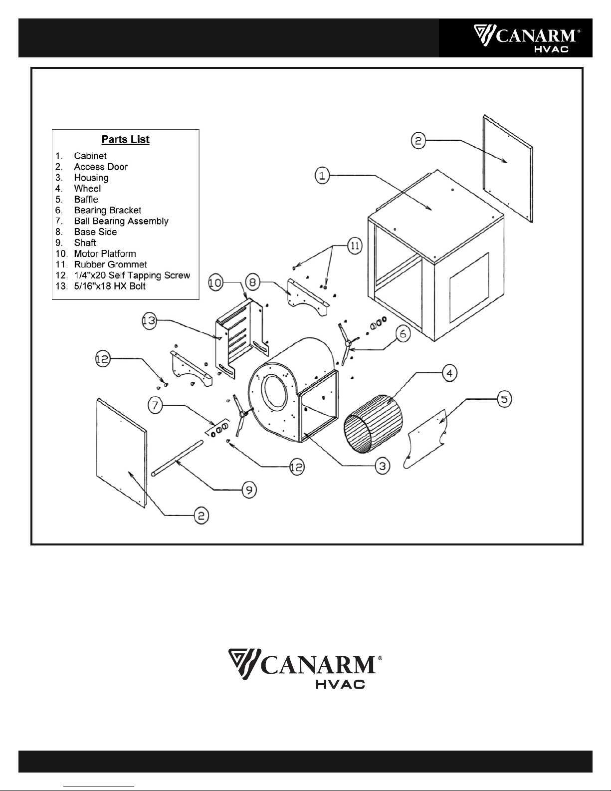
200 & IDB SERIES
INLINE DUCT BLOWERS
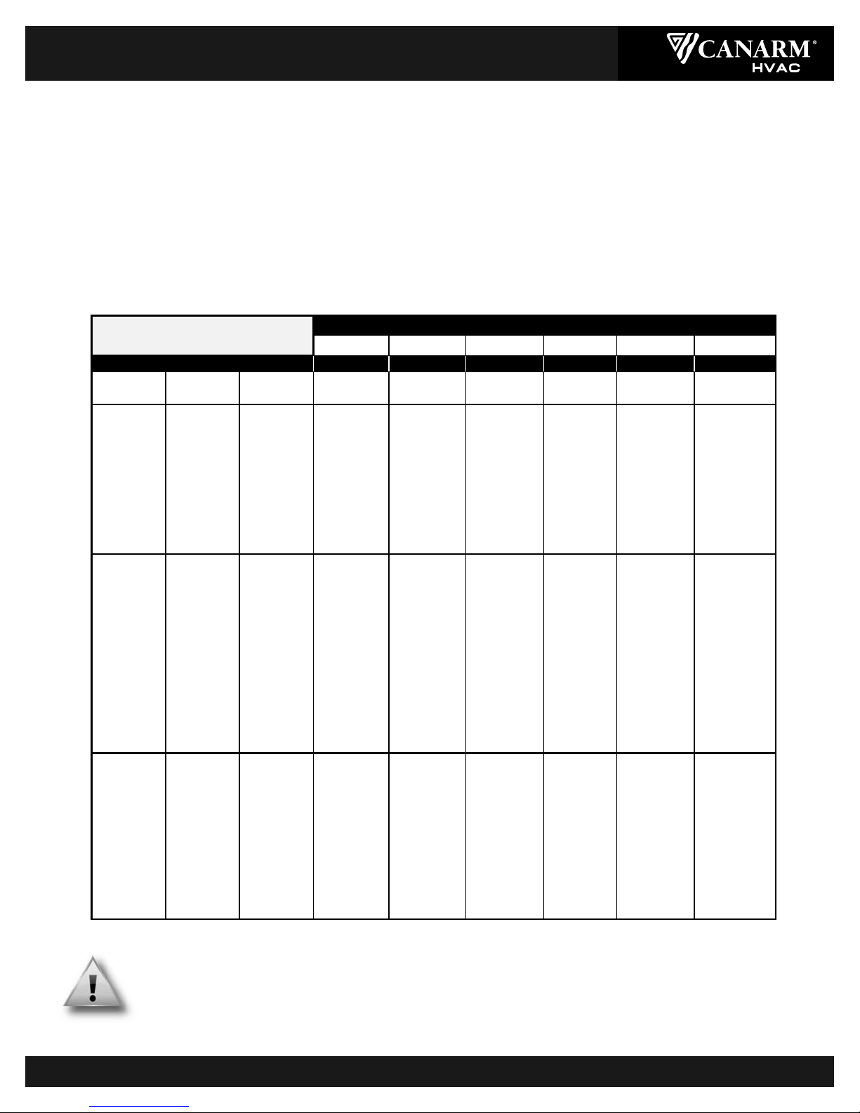
MOTOR, PULLEYS & BELTS (See Table below)
1. Mount the blower pulley on the blower shaft and tighten the set screw securely on the key of the shaft.
2. Mount the motor pulley on the motor shaft. Leave some clearance between the pulley and the motor end bell. Tighten the set screws
on the key of the motor shaft.
3. Install the motor on the motor platform using the hardware provided.
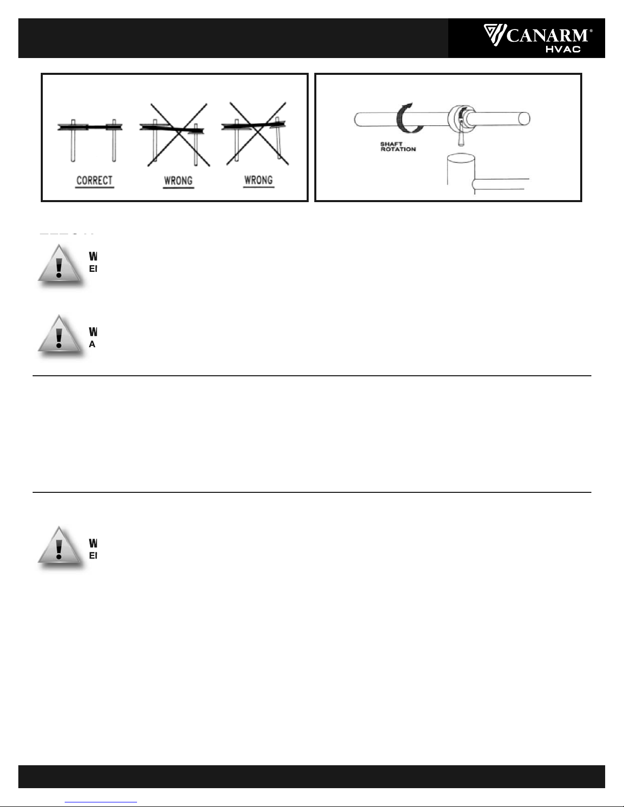
4. With the platform in its minimum position, install the V-belt within the pulley grooves. Position the motor on the motor platform to
ensure proper pulley alignment (see Fig. 2) and secure to the motor platform. (A straight edge across the face of the driven pulley
should be parallel to the belt once proper alignment has been achieved).
Note: Adjustments in the variable speed pulley require pulley re-alignment.
5. Pivot the motor platform to tension the V-belt and lock in place using the 2 bolts on both sides of the blower. (Ideal belt tension is the
lowest tension at which the belt will not slip during start up. A rule of thumb suggests that 3/4" of deflection mid-span under medium
finger pressure (2-3 lbs.) for every foot of span is appropriate.)
WARNING
EXCESSIVE BELT TENSION IS THE MOST FREQUENT CAUSE OF BEARING WEAR AND RESULTING NOISE.
PROPER BELT TENSION IS CRITICAL FOR QUIET EFFICIENT OPERATION.
Ideal belt tension is the lowest value under which belt slip will not occur at peak load conditions.
207 / IDB07 209 / IDB09 210 / IDB10 212 / IDB12 215 / IDB15 218 / IDB18
3/4 3/4 1- 1/21- 1/235
Motor
Pulley
Blower
Pulley
RPM
Range
48
FRAME
48
FRAME
56T/143T & 145T
FRAME
56T/143T & 145T
FRAME
56T/143T & 145T
FRAME
182T/184T
FRAME
- - - - - - - - - - - - - -
IVL34AL104335-511 - - - - - - - - 4L530 4L570- -
& AL94 373-569 - - - - - 4L480 4L510 4L550 - -
1VP34AL84421-642- - 4L430 4L460 4L4904L530 - -
AL74 483-7374L3704L410 4L4404L480 4L510 - -
AL64567-865 4L360 4L3904L420 4L450 4L490- -
3/4 HP AL51 685-10464L3404L3704L400 4L4404L470- -
MAX. AK41 862-1316 4L310 4L360 4L3904L420 4L450 - -
AK30 1170-1786 4L2904L3404L360 4L400 - - - -
BK160H168-333 - - - - - - - - B66
BK140H308-384 - - - - - - - - B61
BK130H333-416 - - - - - - B56 B59
BK120H363-454 - - - - - - B54B57IVL34
IVL34BK110H398-500 - - - - B48B52 B55 &
&BK100H440-555 - - - - B46B50 B53 1VP34
1VP34 BK90H492-625 4L400 4L430 B44 B48B51 not
BK80H559-714 4L380 4L410 B42B46B50 available
BK70H646-833 4L360 4L400 B40B44 B481-1/8"
BK60H766-1000 4L3404L380 B39B43B46bore
BK50H940-1230 4L320 4L360 B37B41B45
BK40H1150-1553 4L310 4L350 B36 B39--
BK130H431-546- - - - - - B57B60 B65
BK120H469-595- - - - B51 B55 B58 B63
BK110H514-655 - - 4L480 B49 B53 B56 B62
BK100H568-728 - - 4L460 B47 B51 B54B60
IVP44 BK90H636-819 4L410 4L440B45B49 B53 B58
BK80H722-936 4L3904L430 B44 B47 B51 B56
BK70H835-10924L3704L410 B42B46B49 B54
BK60H990-13094L350 4L390B40B44 B48- -
BK50H1215-16074L330 4L370B38 B41- - - -
BK40H1509-20484L310 - - - - - - - - - -
MODEL
DRIVE TABLE
MAX HP
200_IDB-M-04_16_13 Page 2 of 4