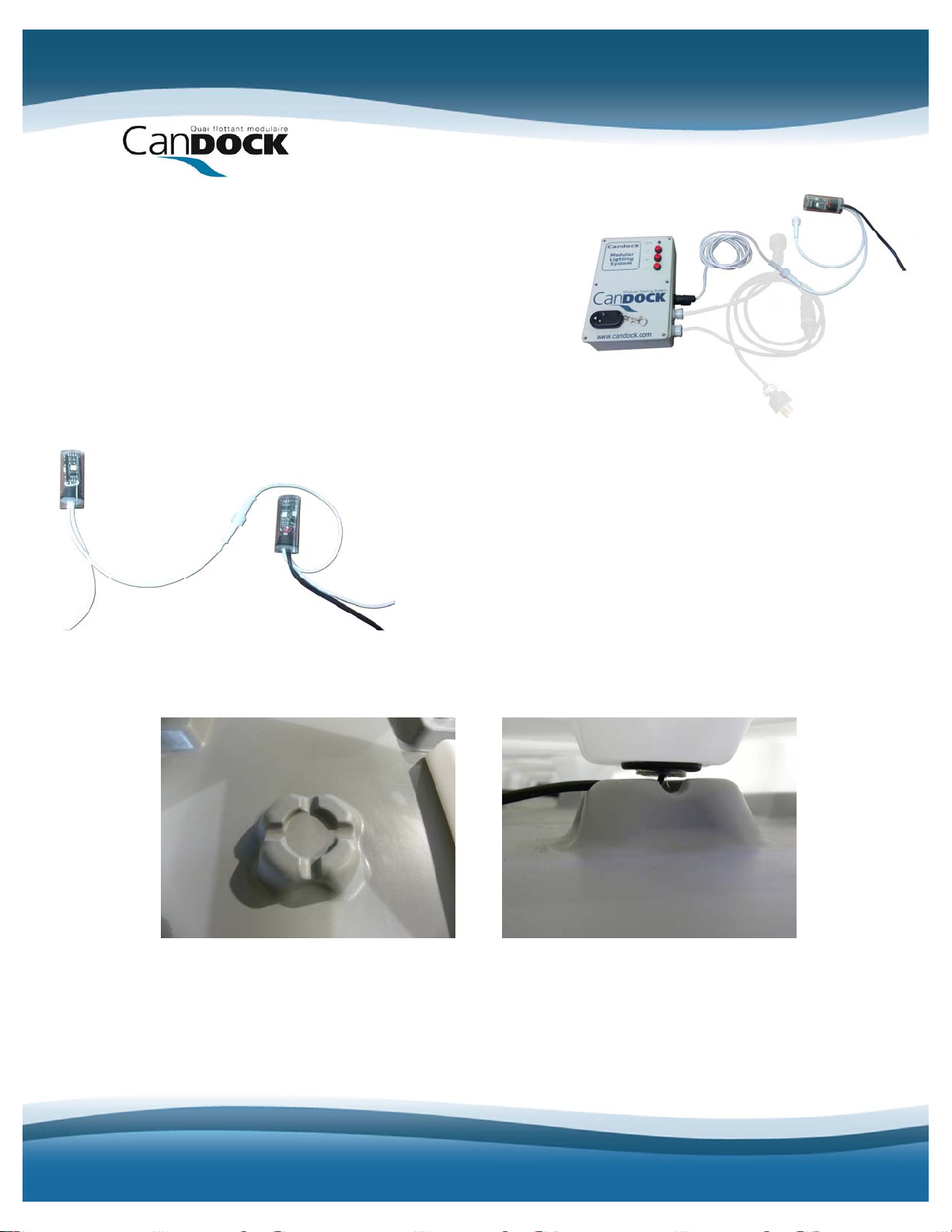
CanDock RGB User manual

INSTALLATION MANUAL
CANDOCK RGB LIGHTS

2
Here are very important details regarding the assembly of Candock RGB lights:
THE FOLLOWING INSTRUCTIONS ARE GUIDELINES TO BE FOLLOWED AND
DAMAGES
CURRED BY THE NON-COMPLIANCE WITH THESE GUIDELINES.
grated light
ystems. Candock Inc. cannot be held responsible in any way for any damages
RESPECTED. CANDOCK WILL NOT BE RESPONSIBLE FOR
IN
All distributors are required and responsible to provide theoretical and practical
training to clients on the complete use of the Candock docks inte
s
resulting from the fact that the client has not received adequate training.

3
A) PRELIMINAIRIES
1. Installation of the Candock modular floating dock.
Com e the dock’s installation without installing the service lids. To do so, refer to
the manua CTION MANUAL"
available at your dealer or online at www.candock.com
plet
l called: "CANDOCK G2 LINE CUBES INSTRU
B) INSTALLATION
A. Put the main 12v power cable in place by putting it on the path created by
Use the cable provided by Candock or a no. 14 12v low
voltage cable made for external features, 2 multi-stranded wires.
OTE:
the service bases.
NIf you must install side lids (lids with
inges), we recommend that you attach them
mediately to their base and to leave them open.
h
im

4
2. Each set of lights has a small rubber ring you must first install on the
service lids.
nges of the hole done
t the factory inside it.
side, it will
o longer be inserted on the other
3. Track the following connector linked to the control box, then split it in two
by following the direction of the arrow indicated on it.
.You must uninstall the part of the connector that is
not linked to the control box (right side on previous
picture) by gently removing the small white latch
The ring has a small slit that allows
putting the fla
a
You will notice that if you push the
ring completely on one
n
side. This is normal, leave the ring at
the middle of the hole.
4
with a small flat screwdriver and by slightly turning
the white part. It will then easily come out of the
black part.

5
5. Unscrew the tip located at the
de.
6. Put the 12v power cable inside the connector by putting the different
ake out the cable enough on the other side of the connector to be able to
plit the cable on 3cm and rip on 1cm.
9. onnect the wire bearing the writings to the one
y gently pulling on the wire, put the white part
11. lose the other extremity of the connector by xaggerating) to make
other end of the connector.
There are 3 small pieces insi
pieces as shown below.
7. T
link it to the previously removed white part.
8. S
C
connector bearing Land the other wire to the
bearing N. Screw in place solidly using the silver
screws.
10. B
back inside the black part and turn to block it in
place.
C
screwing the lid in place. Screw tightly (without e
sure it is sealed.

6
12. Take the black wire linked to the
13. Each light has a black wire (light power
4. Each light has a small black connector in two parts. Take the lower part of
15. Each metallic part of the connector allows an electrical connection with a
control box that has no connector at
its end and connect it to a power
plug adapted for your country. The
blue wire being the negative one,
the brown wire being the positive
one, and the yellow and green wire
being the ground.
cable) and two white wires (light control).
1the connector (bigger one) and put the main cable in the biggest part.
Beware, polarity must be respected to avoid damaging the light and/or
the control box. The part of main power wire bearing the writings must be
linked to the side of the light wire of the light marked in white.
specific side of the wires on it. Make sure the wires lie such as shown in
the following picture. The part of the wire of the main supply bearing
writings must be linked to the side of the
supply wire of the light marked in white.
They must therefore be on the same side
in their respective space.

7
16. Firmly press the wires in the connector. After put the
7. Using both thumbs, press firmly on both parts of the
8. You can now put the lights in place.
se the special tool to enlarge the rubber ring. Place the pointed part in the
Maintain the tool in place with one hand and
emove the tool quickly and immediately insert
20. Gently push the light until the end of
superior part of the connector on the inferior part, making
sure the wires are lying flat.
1connector until you hear a click on each side of the
connector.
1
U
ring and press on the tool for a few seconds.
19. keep the light in the other.
R
the light in the ring.
the light is at the same level as the
ring.

8
21. he lights’ power supply is now
22. These connectors can only be
23. You can now close the lids.
24. Position the light so the wires are lined up with the small cavities in the
25. At this step, you must open the control box by unscrewing the 6 screws
T
complete. You must now link the lights
between each other so the communication
can be made between them and the
control box. Take the white wire of the
control box that should normally already
be linked to it and connect it to the first
light of the series.
connected in one way. The only thing
you now need to do is link the lights
together using the white wires.
service base to avoid them being crushed when the lid is put in place.
that are on top.

9
26. ently remove the lid by paying attention not to disconnect the wires
27. Inside you will find a selector that allows you to choose the appropriate
8. Locate the following selectors. This is where you need to
9. Close the lid and screw tightly to preserve seal.
30. Connect the control box to a supply source and
31. Make sure all the lights are working. If a light is not working, press firmly
32. Finalize the set up of the lids.
eep the control box active during this step to make sure the connections
G
linking the base to the lid.
voltage. Put the selector in the right position. (Beware, selectors are very
fragile)
2select the number of lights used in the system. The lower
selector indicates tens and the above selector units. Ex.: 8
lights (Above 8, Low 0), 25 lights (Above 5, Low 2)
Maximum number of lights that can be use is 63.
(Beware, selectors are very fragile)
2
activate the system by pressing on the OFF
switch (it is possible that the system is already
in function by default). By pressing a second
time on the switch you are turning the system
off. You may also use the remote control.
on the connector to make sure the connexion is made properly. If this does
not work, then check that the wires are placed correctly in the connector.
33. K
were not damaged during the installation of the lids and that lights turn off.

10
34. The system has 10 different selections for the lights: red, blue, green,
35. You can change the selections by using the UP and DOWN switches on
36. Note that the control box is conceived to be inserted under a lid, but this
C) NOTES
yellow, red progressive lighting and turn off. Blue progressive lighting and
turn off, green progressive lighting and turn off, yellow progressive
lighting and turn off, rainbow effect, various lights / various colors.
Customized programming is possible and configurations are
unlimited!!! Contact us for more information.
the control box or by using the remote control provided with the system
(up or down arrow)
involves that the system will only be controlled by the remote control.
I. Lights can be installed and lids closed as you go along.
II. You must make sure not to go over your transformer’s capacity that is of
II. You must never install a cable of more than 100m or 300ft, to avoid power
Contrary to white LED lights that do not have any polarity, RGB lights
onnectors are only conceived for a 14-2 low voltage power cable.
I. If you must remove a light that is already installed in a lid, never remove it
63 lights.
Ilosses.
IV. must be connected in the correct way to avoid any damage. Please follow
instructions to the letter.
V. C
Vby pulling on the wire. Completely push the light inside the lid, remove
the ring and then it will be easy to remove the light from the lid.
Table of contents