Cane Creek Cycling Components • 355 Cane Creek Road • Fletcher, NC 28732
ph:
828.684.3551 • fax: 828.684.1057 • web: www.canecreek.com • e-mail: [email protected]Hooked tool Needle-nose pliers
Required Tools:
8mm socket wrench
section B.Otherwise,the shock is ready to reassemble.
8.Reinstall the lock ring on the piston shaft.The rod wiper end should go onto the shaft first.
9.Reinstall the seal bushing on the piston shaft.Use the assembly collar (Figure 10) supplied in the seal kit to
simplify this step.Place the assembly collar into the open end of the piston shaft and slide the seal bushing
(larger end first) down over the collar into place on the shaft.Be careful not to cut or pinch the seals while
reinstalling the seal bushing.Once the seal bushing is in place remove the assembly collar.
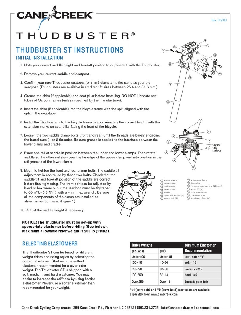
10.Place the compression shim on the step in the compression rod.It should sit flat.Now place the slotted
end of the compression cylinder on the shim.
11.Screw the piston back onto the shaft being careful not to disturb the compression cylinder and compres-
sion shim.Tighten the piston using the spanner wrench or socket wrench with special spanner head.Apply
Cane Creek De-friction Lube to the interior of the large cylinder.Hold the glide ring in place on the piston and
carefully slide the large cylinder down over the piston.
12.Remove the piston end of the shock from the vice,and place the valve end in the vice again.Slide the seal
bushing down the shaft and into the open end of the large cylinder as far as it will go.Now slide the lock ring
over the seal bushing and screw it onto the large cylinder.The lock ring should capture the wire ring at the
end of the threads leaving half of it exposed.Be sure that the wire ring is evenly in place all the way around
the shock.
13.Aligntheeyeletsbyturning the piston shaft.InflatetheAD-12withahand shock pump to about150psi.
Submerge it in water to see if any bubbles come from the shock indicating leaks.If a leak is detected,disas-
semble the shock again and check the appropriate seal for cuts or dirt.If there are no leaks,the shock can be
remounted on the bike and inflated to riding pressure.It may be difficult to compress the shock the first time
since the negative air spring chamber has not been charged.It is charged when the shock is compressed
about 1/2 inch (13 mm).Once it is filled the shock will function normally.
Section B:Tuning Modifications
The AD-12 Rear Shock is designed to be used
with a wide variety of bike frames.The shocks
are built and tuned at the factory for a
particular bike.If the factory settings are not
appropriate for your preferences or riding
abilities you can change the factory setting
relatively easily.There are four different factors
involvedin tuning the AD-12.Air pressureistheeasiesttovary and is usually based on the rider’s weight.
Compression and rebound damping can be set using the adjuster knobs as previously discussed.And,the
volume of the shock can be varied to change the shape of the spring curve.The volume is set by the volume
adjustment plate located in the piston shaft.Moving the plate to a position deeper inside the shaft will
increase the shock’s air volume and make the spring curve more linear.A smaller shock air volume will make
the spring curve more progressive causing the shock to bottom-out less frequently.Changing the air volume
setting is described in the following instructions.If you want to know the setting on your shock or if you have
other questions prior to disassembling it,please call a technical service representative at 800-234-2725.
1.To change the shock’s volume(or repair a leak in the piston shaft eyelet bushing,AD0127)the black,volume
adjustment plate within the piston shaft must first be removed.With the piston shaft still clamped in the vice,remove the aluminum
rebound rod and compression rod by pulling them up and out of the black plate (Using a dry lint free cloth will improve your grip.Do not
use tools that will damage the surface).They will probably come out together.(Figure 7)
2.Insertthe hooked tool into the volumeadjustment plate’sopening and carefullypullitupward,being careful not to damage theplate.
Work from side to side not allowing the plate to become jammed within the shaft.Once you have removed the plate,you will find the
rebound ramp and compression ramp loose inside the piston shaft.They were attached to the rods you removed in step 1.If you are simply
repairing a leak,you can replace the seals on the plate as shown in figure 8,and move to step 4.
3.A small,metal retaining ring will be visible in one of three internal grooves of the piston shaft.This ring positions the plate within the
shaft.Remove the retaining ring from its groove using your fingernail.Do not use tools that could scratch the inside of the shaft.Movethe
ring to the desired groove and snap it back in place.
4.Slide the rebound rod out of the compression rod if they are not already apart,and check the o-ring seal on the rebound rod.You can
replace it with AD0125 from the seal kit.
5.Nest the rebound ramp inside the compression ramp and insert the blunt end of the rebound rod into the hole.If it does not stay
attached,a slight amount of grease on the end of the rebound rod will help keep things together.(Figure 9)
6.Carefully insert the rebound rod assembly into the black ramp housing in the bottom of the piston shaft.The ramped side of the re-
bound and compression ramps should face toward the external adjuster knobs.Both adjuster knobs should be backed out 2 - 3 turns from
the full-in position when reassembling the shock.Note:the adjuster knobs should never be removed from the piston shaft.Doing so
will damage them.
7.Before reinstalling the volume adjustment plate inspect the seals for cuts or dirt that may allow leaks.Lubricate the seals and push the
platecarefullydownintothe shaft,keepingit level (Be careful not tocutorpinchthesealswhilereinstallingthe volume adjustmentplate).
The sharp end of the rebound rod will protrude loosely through the hole in the center of the plate.If the plate gets stuck remove the
rebound rod,plate,and ramps;and start over.When properly installed,the groove (or four side holes in the shaft if the plate is in the highest
position) will be barely visible just above the plate.
8.Slide the compression rod (shiny end up) down over the rebound rod and through the hole in the plate.It will be a little tight going past
the seals.Be careful not to cut them in the process.
9.The shock is readyfor re-assembly.Returnto step8ofSection A.
WARRANTY
Cane Creek Cycling Components warrants its bicycle components for a period of two years from the original date of purchase. Any
Component that is found to be defective in materials or workmanship will be repaired or replaced at the discretion of Cane Creek. This
warranty applies to the original owneronly. This warranty does not coverdamage or failure resultingfrommisuse,abuse,alteration,
neglect,wear and tear,crash or impact,lack of maintenance or other conditions judged by Cane Creek to be abnormal,excessive, or
improper. Itis mandatorythata ReturnAuthorization Number (RA#)isobtainedbycalling Cane Creek beforeanyproduct is returned.
Additionally,a dated Proof of Purchase must accompany the product when returned. (Revised 5.12.2003)
volume
adjustment
late
comp.
ramp
reboun
ramp
comp.
ro
reboun
ro
iston
shaft
retaining
ring
Figure7
o-ringsea
AD012
hooked
tool
Figure8
o-ringsea
D0110
o-ringseal
D0106
volume
adjustmen
plate
Figure9
rebound
rod
rebound
ramp
compression
ramp
seal
bushing
assembly
collar
iston
shaft
lock
ring
Figure10
