Cutting Steerer Tube:
Cut the steerer tube using a good quality
hacksaw and an appropriate guide. To ensure
a clean cut always use a sharp, ne toothed
hacksaw blade. Be sure to le and de-burr the
freshly cut edge before assembly. It can be helpful
when cutting threaded steerers to thread the
headset top cover or a threading die onto the fork
before cutting. Once cut, simply un-thread the top
cover or die to clean-up the threads.
Steerer Tube Length
For the safe and proper installation of a
threaded headset system it is imperative that the
top of the fork’s steerer tube does not bottom out
on the locknut when fully assembled. In order to
achieve this it may be necessary to cut the steerer
tube or insert additional spacers between the top
cover and locknut. To prevent damage to the
aluminum locknut, ensure that the locknut threads
on at least 3 full revolutions before tightening. If it
does not, the steerer tube is too short or there are
too many spacers in the assembly.
The following formula may be used to
determine the proper steerer tube length:
Installing the Bearing Cups:
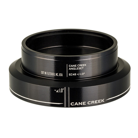
Press the upper and lower bearing cups
into the head tube using a good quality headset
press. It is often easier and more precise to press
in one cup at a time.
The 100 headsets are equipped with drop-
in bearings for easy replacement and tolerance to
frame/fork misalignment. When pressing the cups
into the frame the bearings should be removed.
Cup installation is best done using Cane Creek
headset installation tools to press directly on the
bearing seats. These tools are designed to ensure
the safe installation of all Cane Creek Headsets
and are available through your local Cane Creek
dealer.
Installing the Crown Race:
Press the fork crown race onto the fork
with an appropriate crown race installation tool until
the bottom of the race is ush with the fork crown.
This should be a press t.
Frame and Fork Preparation:
Use head tube reaming and facing tools
to prepare the top and bottom of the frame’s head
tube. (Be sure to use the correct reamer diameter
corresponding to the headset being installed.)
Use a crown race cutting tool to turn and
face the crown race seat of the fork, again being
sure to use the correct diameter tool.
Adjusting the Headset Assembly:
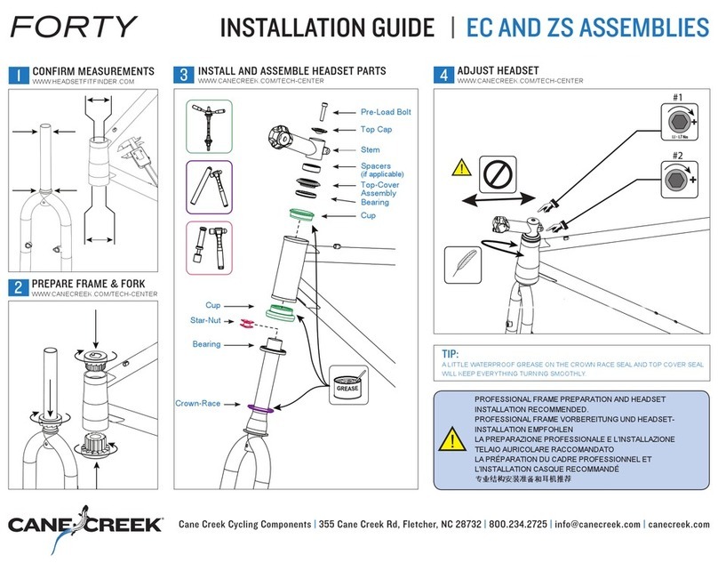
With the headset installed and assembled
insert the fork into the frame. Apply a quality water-
proof grease to the fork threads and thread the
top cover onto the fork until it makes contact with
the upper bearing. Next assemble the key-washer
and any necessary spacers and then thread-on the
lock nut but do not tighten. Carefully tighten the
top cover until all play is taken out of the headset
assembly, this should require very little force. To
lock this adjustment in place it is necessary to
rmly tighten the locknut against the top cover. Do
this by holding the top cover in place with a 32mm
wrench while tightening the locknut with another
32mm wrench. Check for play by rmly holding the
front brake and rocking the bike backwards and
forwards. With the headset properly adjusted there
should be no play in the assembly and the fork
should rotate easily without binding.
ST Length = Lower Stack Height(11.65mm)
+ Head Tube Length + Upper Stack Height
(25.5mm) + Height of Spacers(if any) - 2mm
Notes:
If the headset will not tighten properly check to1.
be sure your steerer tube has enough threads
to allow the top cover to fully contact the upper
bearing.
If there are problems threading the top cover2.
and locknut onto the fork, ensure that the
threads are clean and un-damaged.
If the headset binds, be sure that the preload3.
adjustment is not too tight. If binding occurs
even with proper adjustment this could be a sign
that the frame and/or fork needs to be reemed
and faced.
After an initial break-in period it may be 4.
necessary to repeat this process. As with all
threaded headset systems regular checks
should be made to check the headset for proper
adjustment.
Installation and removal of the upper seal:
Cane Creek 100 Classic headsets are
equipped with a special rubber seal above the
upper bearing to help guard against contamination.
On the threaded headset this seal is press-t onto
the top cover. If it becomes necessary to remove
or replace this seal the process is fairly easy.
To remove the seal use a small, thin, at-
bladed screw-driver or similar instrument to pry the
seal off of its seat. This should not take very much
force.
To install the seal, nd a cylinder with an
inside diameter very slightly larger than 29.1mm (a
socket or 1-1/8” crown race works nicely). Place
Set-Screw Adjustment:
The 100 Classic is equipped with a key-
washer that goes between the top cover and the
locknut. The purpose of this washer is to separate
the rotation of the top cover and locknut. The “key”
is formed by the small set-screw installed in the
washer and is designed to interface with the small
slot machined into the threads of most steerer
tubes.
These slots are not necessarily
standardized so the set-screw conguration allows
the user to adjust the depth of the “key” to t his or
her particular fork. Also, if the fork is not equipped
with said slot, the key may be completely removed
from the washer.
To adjust the key, use the included 1.5mm
hex wrench to move the set-screw in and out of
the washer. The screw should be adjusted as far
inwards as possible while still allowing the washer
to ride freely up and down the steerer tube. The
set-screw should also not be adjusted so far out
that the key-washer assembly will not nest inside
the recess on the top of the top cover.
the seal over the conical face on the top cover and
ensure that the concave face of the seal faces
towards the bearing. Next, place the cylinder
over the seal and press rmly with hand pressure
only. There should be a slight popping or scraping
noise as the seal slides over the top cover. Check
to ensure that the seal is seated correctly and re-
assemble the headset.
