Cane Creek Helm User manual

SUSPENSION FORK INSTRUCTION MANUAL

2

3
Safety Warning Information
Tools Needed
Fork Features Overview
Crown Race Installation
Steerer Tube Cutting and Star Nut Installation
Stem Installation and Headset Preload
Front Brake and Cable Guide Screw/Cover Installation
D-Loc Axle Installation
Air Spring
Air Volume Adjustment
Damper Adjustments
Internal Travel Adjustment
Service and Maintenance Schedule
Warranty Information
04 ....
05 ....
06 ....
07 ....
08 ....
09 ....
10 ....
11 ....
13 ....
16 ....
18 ....
20 ....
25 ....
26 ....
Table of Contents

4
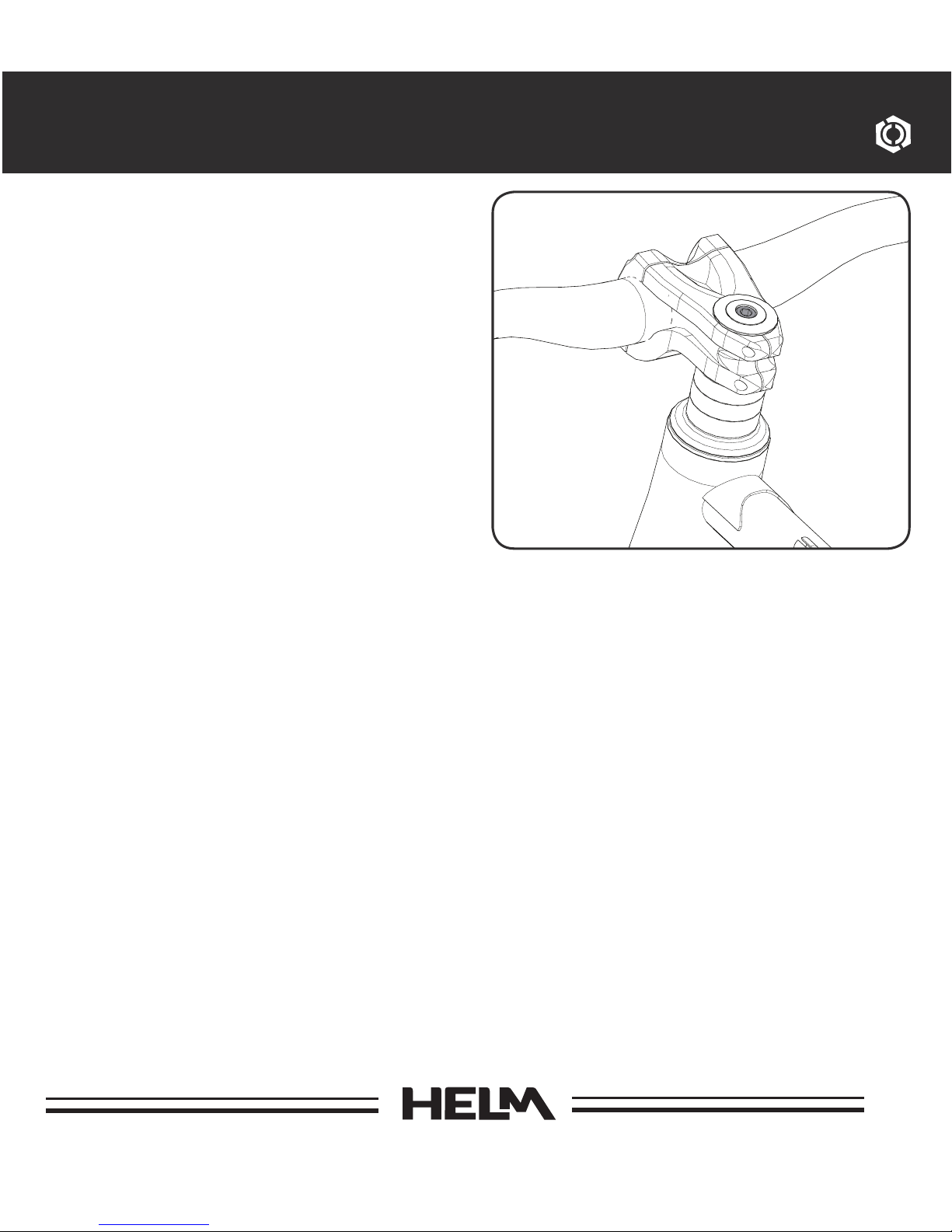
The fork is an important part of your
bicycle. Before installing and using
your new front fork, carefully read this
owner’s manual to learn the correct
installation and adjustment procedures
of this fork.
Warning
Improperly installed and/or adjusted
forks can cause serious harm or death
and may severely damage your bicycle.
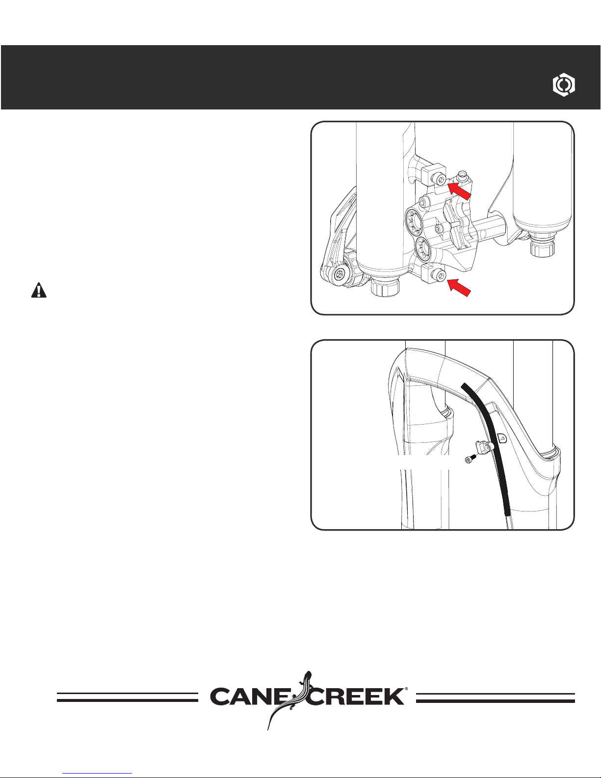
Warning
A broken or malfunctioning fork may
cause loss of vehicle control and result
in SERIOUS INJURY OR DEATH. If the
fork ever loses oil, air or makes
unusual noises, stop riding and have
the fork inspected by a Cane Creek
Authorized Suspension Service Center
or call the Cane Creek Customer
Service Team.
Warning
Modification, improper service or use
of aftermarket replacement parts voids
the warranty and may cause the fork to
malfunction, resulting in loss of vehicle
Safety Warnings
control and SERIOUS INJURY OR
DEATH. Do not modify your bike frame
or fork. Use only genuine Cane Creek
Helm parts.
Follow service maintenance
recommendations. Fork service
should be performed by Cane Creek
Cycling Components or a Cane Creek
Authorized Suspension Service Center.
Visit www.canecreek.com or contact
us at 800-234-2725 to locate a Cane
Creek Authorized Suspension
Service Center.

5
Tools Needed
Tools Needed For Installation:
• Saw for cutting steerer
• Crownrace setter (Recommended
Cane Creek part code HST005)
• Star Nut Setter (Recommended:
Cane Creek part code .TL1100 and
.TL1102)
• 2.5mm hex wrench
Tools Needed For Maintenance:
• 2.5mm hex wrench
• 13mm wrench
• 18mm wrench
• 22mm wrench
• 30mm wrench
Specialized tools and materials are
needed for the installation of your Cane
Creek parts. Installation of Cane Creek
parts by a qualified bicycle mechanic is
highly recommended.

6
Fork Features Overview
Wheel Spacing Boost 110mm
Brake Connection Post Mount 180mm Rotor Size Adaptor Needed
For 200mm Rotor
Tire Clearance Maximum Tire
Size
Air Pressure Minimum = 30psi Maximum = 150psi Recommended
Sag 15-25%
Compression Low Speed 20 Clicks
Compression High Speed 10 Clicks
Rebound Low Speed 15 Clicks
Volume Reduction Indexed 8 Positions
Travel Reduction Indexed System 10mm Reducer Maximum 7
Reducers (100mm
Travel)
Max 65mm wide by 714mm tall. WARNING: Due
to wide variations in rim and tire widths, always
check tire clearance before riding. Remove air
and compress the fork completely to verify at
least 10mm of clearance across the complete
arc of the tire and the crown.

7
Crown Race Installation:
After installing a headset into the bicycle
frame, install the crown race included
with the headset onto the fork according to
the headset manufacturers instructions.
Crown Race Installation

8
Steerer Tube Cutting:
Measure the steerer tube twice and
cut to length according to the stem
manufacturers instructions.
WARNING: Do not install more than
30mm of spacers below the stem.
Star Nut Installation:
Use a star nut setter tool to install
a star nut into the steerer tube at a
depth of 15mm.
Steerer Tube Cutting and Star Nut Installation

9
Stem Installation and Headset Preload:
Install fork into frame and stem on
steerer tube. Tighten headset and
stem according to the manufacturer’s
instructions.
Stem Installation and Headset Preload

10
Front Brake and Cable Guide Installation
Front Brake and Cable Guide Screw/
Cover Installation:
Install brake caliper according to the
brake manufacturer’s instructions.
Route the front disc brake hose or
cable housing on the inside of the
lower fork leg through the disc brake
housing guide.
WARNING: Ensure that all bolts are
tightened to the correct torque and
that fork movement is not restricted by
improper assembly when the suspension
is fully compressed or extended.
Torque to 1Nm Max

11
1. Remove D-LOC axle from fork
by opening the cam lever, then
moving the axle lock latch to the
“unlocked” position and slide the
axle out of the fork.
2. Install front wheel into the dropouts
and insert the D-LOC axle with text
“THIS SIDE UP” facing towards
the head tube through the dropout.
Use an anti seize or grease on axle
shaft to promote longevity of axle
function.
D-Loc Axle Installation
THIS SIDE UP
1.
2.
Cam Lever
Latch Lock

12
3. Lock the D-LOC axle lock latch.
4. Use the tension adjuster to
adjust the axle’s clamp strength
and close axle lever to complete
wheel installation.
WARNING: An improperly
tensioned axle, a lever not
completely engaged or a lever not
positioned in the upward closed
position could result in disengagement
of the axle and possibly causing
serious injury or death.
D-Loc Axle Installation
3.
4.
Tension Adjuster

13
Setting Sag is a crucial part of set up as it
affects the ride height and head angle of
bicycle. Follow these steps carefully.
1. Unscrew AIR top cap to reveal air
valve and thread on shock specific
pump.
2. Start by adding around half of your
body weight (in lbs) in psi to the
positive chamber of the fork.
For example a 150lb rider, should
start with 75psi and adjust from
there if necessary.
3. Unscrew cap on lower leg to reveal
the negative air chamber equalizing
system. Unthread equalizing valve
and press button in to allow air into
the negative chamber. Charging
negative air chamber via the
equalizing button will reduce overall
pressure in the positive chamber.
Air Spring Set Up
REMOVEREMOVE
1.
3.

14
WARNING: The fork can become
lowered when applying downward
force while the negative air equalizer
button is pressed, falsely lowering
the travel of the fork as more air
volume is moved from the positive
chamber to the negative chamber.
If this occurs, press negative air
chamber equalizer button down
and pull up on the uppers of the
fork until full travel is restored.
4. Move sag ring indicator to the
wiper seal of the fork according to
the illustration.
5. Dressed in full riding gear, mount
bicycle via normal descending ride
position. Push down on fork to
cycle travel 3-5 times. Then return
sag ring indicator to the wiper seal
at your sag position.
6. Step off bicycle and measure the
sag O-ring movement distance.
Sag should be set approximately
15-25% of the total fork travel. Set
sag with damper compression
settings fully open to prevent damper
influence during this procedure.
Air Spring Set Up
4.
6.
Wiper Seal

15
7. Too little sag: Release air pressure
from air valve, and equalize
negative chamber. Too much sag:
Increase air pressure and equalize
negative chamber.
For sag recommendations and trouble-
shooting contact Cane Creek Cycling
Components customer service at
1-800-234-2725
Recomended Air Pressure:
We recommend inflating the Helm fork
with air pressure equal to half of your
body weight (in lbs) in psi. Example 150lb
rider weight, start with 75psi and adjust
from there if necessary.
Due to variations in travel, volume
reduction settings, and rider standing
position air pressure will vary. This guide
is intended to be used during initial set
up and only provides recommendations
for air pressure and is not intended to
define settings in air pressure.
Air Spring Set Up
To much.
To little.
7.

16
If sag is set properly, but you are using
all of the fork’s travel prematurely,
a reduction of volume should be
performed. Cane Creek’s air volume
reduction system allows any rider to
achieve their desired “bottomless”
feel without the need for additional
materials. The system uses a static
piston that is positioned on an indexed
rod. This piston can be moved down the
rod to decrease volume in the positive
air chamber and increase the ramp of
the air spring. Increased ramp = more
progressive.
1. WARNING: If working on air
spring be sure to remove all air
from positive and negative air
chambers.
2. Remove AIR top cap on left side leg
and release air pressure from the
top of the fork.
WARNING: Be sure all air
pressure is released before the
next step.Using a 30mm Wrench,
turn air valve assembly counter-
clockwise.
Air Volume Adjustment
1.
Tools Needed:
• 30mm Wrench
• Shock Pump
Air Top Cap
Air Valve
Assembly

17
3. Remove air valve assembly and
unthread the air volume piston
wing nut.
4. Reposition air volume piston to
desired reduction and refasten the
air volume piston wing nut.
5. Reinstall air valve assembly, torque
to 36Nm, and set sag.
Air Volume Adjustment
3./4.
4.
Wing Nut
Air Volume
Piston

18
Compression Damping:
Compression damping controls the
how easily the fork compresses under
impacts.
Low Speed Compression:
Is used to manage traction and chassis
stabilization. LSC adjustment eliminates
pedal induced “bob”, influences small
bump sensitivity, reduces brake dive
and determines how the bike will react
to weight changes. To adjust, turn
middle adjuster on the top of the right
side leg labeled Low Speed Compression.
Turn clockwise to increase damping, turn
counterclockwise to decrease damping.
High Speed Compression:
Is critical to absorbing energy from
high impact forces, such as square
edge hits and harsh landings. It also
aids in bottom-out resistance. To adjust,
turn outside adjuster on the top of
the right side leg labeled High Speed
Compression. Turn clockwise to increase
damping, turn counterclockwise to
decrease damping.
Damper Adjustments
High Speed
Compression
Low Speed
Compression

19
Damper Adjustments
Rebound Damping:
Rebound damping controls the speed
at which the fork will return to normal
height after a compression cycle. To
adjust, turn adjuster on the bottom of
the right side leg labeled Rebound. Turn
clockwise to increase damping, turn
counterclockwise to decrease damping.
Rebound

20
Internal Travel Adjustment
Cane Creek Helm fork travel is preset
from the factory, but travel can be
changed internally in 10mm increments
if desired. Two travel reducers are
included with every HELM fork.
Tools required:
• 13mm Wrench
• 18mm Wrench
• 22mm Wrench
• Travel Reducers
WARNING: READ ALL STEPS
BEFORE PERFORMING TRAVEL
ADJUSTMENT Follow these steps
carefully to avoid foul assembly,
warranty void, or serious injury. If you
do not feel confident performing this
procedure, contact a professional bike
mechanic or a Cane Creek authorized
Service Center. *For a detailed step by
step video of this process, visit http://
www.canecreek.com/tech-center/sus-
pension/service-videos*
1. Remove air cap from top of fork,
remove charge air cap off bottom of
fork, unthread air charge button on
bottom of fork.
1.
Travel Reducers
Table of contents
Other Cane Creek Bicycle Accessories manuals

Cane Creek
Cane Creek 100 Classic User manual

Cane Creek
Cane Creek DB Kitsuma User manual

Cane Creek
Cane Creek DROPT Service manual

Cane Creek
Cane Creek AngleSet EC44 User manual

Cane Creek
Cane Creek eeSilk System manual

Cane Creek
Cane Creek CANE CREEK AD5 REAR SHOCK User manual

Cane Creek
Cane Creek EC Operating and maintenance instructions

Cane Creek
Cane Creek eeSilk System manual

Cane Creek
Cane Creek CANE CREEK THUDBUSTER User manual

Cane Creek
Cane Creek Helm MKII User manual