Canoga Perkins 2240 User manual

Modems
Model 2240
Fiber Optic Modem
Users Manual

2
Canoga Perkins
Caution!
This product may contain a laser diode emitter operating at a wavelength of 1300 nm - 1600 nm. Use
of optical instruments (for example: collimating optics) with this product may increase eye hazard.
Use of controls or adjustments or performing procedures other than those specified herein may result
in hazardous radiation exposure.
Under normal conditions, the radiation levels emitted by this product are under the Class 1 limits in 21
CFR Chapter 1, Subchapter J.
Notice!
This device contains static sensitive components. It should be handled only with proper Electro-
static Discharge (ESD) grounding procedures.
ATTENTION!
Cet équipement peut avoir une diode laser émettant à des longueurs d'onde allant de 1300nm à
1600nm. L’utilisation d’instruments optiques (par exemple : un collimateur optique) avec cet
équipement peut s’avèrer dangereuse pour les yeux. Procéder à des contrôles, des ajustements ou toute
procédure autre que celles décrites ci-après peut provoquer une exposition dangereuse à des radia-
tions.
Sous des conditions normales, le niveau des radiations émises par cet équipement est en dessous des
limites prescrites dans CFR21, chapitre 1, sous chapitre J.
NOTE!
Cet équipement contient des composants sensibles aux décharges électro-statiques. Il doit
absolument être manipulé en respectant les règles de mise à la terre afin de prévenir de telles
décharges.

2240 Fiber Optic Modem
3
Notice!
Canoga Perkins has prepared this manual for use by customers and Canoga Perkins person-
nel as a guide for the proper installation, operation and/or maintenance of Canoga Perkins
equipment. The drawings, specifications and information contained in this document are the
property of Canoga Perkins and any unauthorized use or disclosure of such drawings,
specifications and information is prohibited.
Canoga Perkins reserves the right to change or update the contents of this manual and to
change the specifications of its products at any time without prior notification. Every effort has
been made to keep the information in this document current and accurate as of the date of
publication or revision. However, no guarantee is given or implied that the document is error
free or that it is accurate with regard to any specification.
CANOGA PERKINS CORPORATION
An Inductotherm Company
20600 Prairie Street
Chatsworth, CA 91311-6008
Business Phone: (818) 718-6300
(Monday through Friday 7 a.m. - 5 p.m. Pacific Time)
FAX: (818) 718-6312 (24 hrs.)
Web Site: www.canoga.com
Email: [email protected]
Copyright © 1991, 1992, 1993, 1994, 1996, 1997, 1998, 2000, 2001
Canoga Perkins Corporation
All Rights Reserved
Model 2240
Fiber Optic Modem
Model Number 2240 - UM
Users Manual
Part Number 6911100
Rev. K 06/2001
To reference Technical Advisories and Product Release Notes, go to Canoga Perkins’
website:http://www.canoga.com/cservice.htm

4
Canoga Perkins
Model 2240 Fiber Optic Modem

2240 Fiber Optic Modem
5
Table of Contents
1. Description .................................................... 11
1.1 2240 Modem................................................................11
1.1.1 Functions, LEDs and Switches ............................................. 12
1.2 2201 Rack Chassis ......................................................13
1.3 2202 Modem Shelf ......................................................13
1.4 2200R Series Redundant Card..................................14
1.5 Modem Operation ......................................................14
1.5.1 General .................................................................................. 14
1.5.2 System Test and Diagnostics ................................................ 16
1.5.3 Transmit Section ................................................................... 16
1.5.4 Receive Section ..................................................................... 17
1.5.5 Expanded Interface Control Channels .................................. 17
1.5.6 Expanded Interface Auxiliary Channels ............................... 17
1.5.7 Fiber Optics ........................................................................... 18
1.6 Loss Budget.................................................................18
1.7 Initial Unit Testing .....................................................18
2. Installation and Setup .................................. 19
2.1 Installation ..................................................................19
2.1.1 Unpacking the Unit ............................................................... 19
2.1.2 Standalone Modem Installation ............................................ 19
2.1.3 Rack-Mount Modem Installation .......................................... 20
2.1.4 Fiber Cable and Connectors .................................................. 20
2.1.5 2202 Modem Shelf Installation............................................. 21
2.1.6 Custom Oscillator Installation .............................................. 21
2.2 Setup ............................................................................22
2.2.1 HI / LO Optic Power Switch ................................................. 22
2.2.2 Internal Control Switches...................................................... 24
2.2.2.1 Carrier Detect (CD) Signal Options ................................... 24
2.2.2.2 Internal Clock Option Switches ......................................... 25
2.2.2.2.1 TBL / NORM Switch ...................................................... 25
2.2.2.2.2 CLK / EXT Switch .......................................................... 25
2.2.3 Signal Ground Strap.............................................................. 26
2.2.4 SCT Normal / Invert Jumper ................................................. 26
2.2.5 EXTRA CLOCK Jumper ...................................................... 27

6
Canoga Perkins
3. Mode and Rate Selection ............................ 29
3.1 Operating Mode / Data Rate Selection .....................29
3.2 External Clock Modes................................................31
3.2.1 Sampled External Clock Mode - Mode 0............................... 31
3.2.2 Locked External Clock Mode - Mode 7................................. 32
3.3 Internal Clock Modes - Modes 1, 2, 3, 4 ...................32
3.3.1 Standard Internal Clock Rates (Groups 1, 2 and 3) ............... 33
3.3.2 Custom Internal Clock Rates (Group 4) ................................ 33
3.4 Slave Clock Mode - Mode 5 .......................................35
3.4.1 Loopback Clock for Slave Mode ........................................... 35
3.5 Asynchronous Mode - Mode 6...................................35
3.6 Consideration of Propagation Delays .......................37
3.7 Internal Clock Option Switches .................................38
3.7.1 TBL / NORM Switch ............................................................. 38
3.7.2 CLK / EXT Switch ................................................................ 38
4. Data Interfaces.............................................. 41
4.1 Data Interfaces Overview ..........................................41
4.2 RS-423 / 232D Model 432...........................................42
4.2.1 RTS_BIAS Jumper ............................................................... 44
4.2.2 DCD Jumper ......................................................................... 44
4.2.3 CTS_GATE Jumper .............................................................. 44
4.2.4 DSR Jumper .......................................................................... 45
4.2.5 CH_GND Jumper.................................................................. 45
4.3 RS-449 / 422 Model 422..............................................45
4.3.1 RS_BIAS Jumper .................................................................. 48
4.3.2 RR Jumper............................................................................. 48
4.3.3 CS_GATE Jumper ................................................................ 48
4.3.4 DM Jumper ........................................................................... 49
4.3.5 CH_GND Jumper.................................................................. 49
4.3.6 UNBAL_REF Jumper ........................................................... 49
4.4 RS-530 Interface Model 430 ......................................50
4.4.1 RTS_BIAS Jumper ............................................................... 52
4.4.2 DCD Jumper ......................................................................... 52

2240 Fiber Optic Modem
7
4.4.3 DSR Jumper .......................................................................... 52
4.4.4 CHASSIS_GND Jumper ....................................................... 52
4.4.5 SCT Switch ........................................................................... 54
4.4.6 CTS_GATE Jumper .............................................................. 54
4.4.7 CTS_OUT Jumper ................................................................ 54
4.4.8 CTS (A) Jumper .................................................................... 54
4.4.8.1 KG_SWING Jumper .......................................................... 54
4.4.8.2 KG_OUT Jumper ............................................................... 54
4.5 CCITT V.35 (ISO 2593-1993) Model 436.................55
4.5.1 RTS_BIAS Jumper ............................................................... 58
4.5.2 DCD Jumper ......................................................................... 58
4.5.3 CTS_GATE Jumper .............................................................. 58
4.5.4 DSR Jumper .......................................................................... 59
4.5.5 CH_GND Jumper.................................................................. 59
4.6 Multi-Channel Interfaces...........................................60
4.6.1 RS-449 / RS-423 Model MC1 .............................................. 60
4.6.1.1 RS-449 / DC-37 Interface .................................................. 61
4.6.1.1.1 RS_BIAS Jumper ............................................................ 63
4.6.1.1.2 RR Jumper....................................................................... 63
4.6.1.1.3 CS_GATE Jumper .......................................................... 63
4.6.1.1.4 CH_GND Jumper............................................................ 64
4.6.1.1.5 UNBAL_REF Jumper ..................................................... 64
4.6.1.2 RS-423 / DB-25 Interface .................................................. 64
4.6.2 V.35 / RS-423 Model MC2 .................................................. 66
4.6.2.1 CCITT V.35 / MRC 34 Interface ....................................... 67
4.6.2.1.1 RTS_BIAS Jumper ......................................................... 69
4.6.2.1.2 DCD Jumper ................................................................... 70
4.6.2.1.3 CTS_GATE Jumper ........................................................ 70
4.6.2.1.4 CH_GND Jumper............................................................ 70
4.6.2.2 RS-423 / DB-25 Interface .................................................. 71
4.7 T1 / E1 Interfaces .......................................................71
4.7.1 Transparent Bipolar - Models 4BX ....................................... 71
4.8 TTL / BNC Interface Model -BN ..............................75
4.9 Programmable Buffered Interface / Model P53 ......76
4.9.1 Jumper Settings ..................................................................... 80

8
Canoga Perkins
4.9.2 Generic Interface ................................................................... 81
4.9.3 External Station ..................................................................... 82
4.9.4 Internal ................................................................................. 83
4.9.5 External ................................................................................. 84
4.9.6 DTE Adapter ......................................................................... 85
4.9.7 Legacy Adapter ..................................................................... 86
4.10 High-Speed RS-422 / Mil-Std 188-114C .....................
Interfaces..........................................................................87
4.10.1 Model TW ........................................................................... 87
4.10.2 Model TW8 ......................................................................... 90
4.10.3 Model T22........................................................................... 91
4.10.4 Model T88........................................................................... 91
4.10.5 Model D22 .......................................................................... 91
4.10.6 Model D88 .......................................................................... 91
4.11 Interface Reconfiguration........................................93
4.12 Standalone Reconfiguration ....................................94
5. Troubleshooting............................................ 95
5.1 Diagnostic Procedures................................................95
5.2 Local and Remote Loopback.....................................95
5.2.1 Loopback Tests ...................................................................... 95
5.2.2 Remote Loopback Test .......................................................... 96
6. Diagnostic Procedures.................................. 97
6.1 2240 / 2201 Diagnostic Procedures............................97
6.1.1 Required Equipment ............................................................. 97
6.2 Loopback Test Diagnostic Procedure.......................98
6.3 Fiber Optic Diagnostic Procedure ..........................100
7. Specifications .............................................. 101
7.1 Optical Interface.......................................................101
7.2 System Electrical ......................................................102
7.3 Indicators and Controls ...........................................103
7.4 Physical / Environmental:........................................103
7.5 2240 Fiber Optic Modem Configurations ..............104
APPENDIX A Limited Warranty.................. 105

2240 Fiber Optic Modem
9
List of Figures
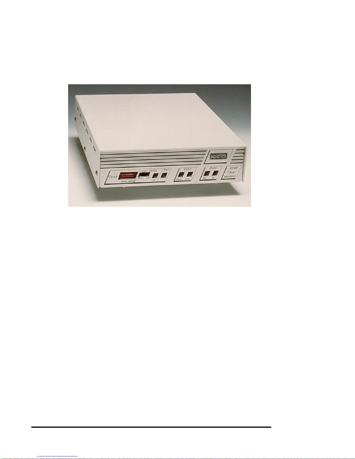
1-1 Model 2240 Modem .......................................................................................... 11
1-2 Model 2201 Rack Chassis................................................................................. 13
1-3 Model 2202 Modem Shelf................................................................................. 14
1-4 2240 Functional Block Diagram ...................................................................... 15
2-1 2240 Standalone Rear Panel Layout ............................................................... 20
2-2 Location of Oscillators ..................................................................................... 21
2-3 Eight-Position Internal Options DIP Switch .................................................. 23
2-4 Factory Setting for CD / DCD or CD / SYNC Switches ................................ 24
2-5 Extra Clock Pins in Tail Circuit Application at Clock Source End ............ 28
3-1 2240 Front Panel Mode / Rate Switches ......................................................... 29
3-2 Typical Tail Circuit Implementation .............................................................. 36
3-3 RS-449 / 422 Null Cable Diagram for 2240 .................................................... 36
3-4 Location of Internal Switches and Jumpers................................................... 39
4-1 Interchangeable Interfaces............................................................................... 41
4-2 Transparent Bipolar Interface Connectors .................................................... 74
4-3 Example of Link Between Bipolar and Clocked Interface............................ 74
4-4 BNC Connectors ............................................................................................... 75
4-5 Available Strapping Options for Programmable Buffered Interface.......... 78
4-6 Board Layout for Programmable Buffered Interface................................... 79
4-7 Programmable Buffered Interface, Model P53, Basic DCE RS-530............ 81
4-8 External Station Programmable Buffered Interface, Model P53,
DCE RS-530 .................................................................................................. 82
4-9 Programmable Buffered Interface, Model P53, External Station ............... 82
4-10 Internal Programmable Buffered Interface, Model P53, DCE RS-530....... 83
4-11 Internal Programmable Buffered Interface, Model P53 .............................. 83
4-12 External Programmable Buffered Interface, Model P53, DCE RS-530...... 84
4-13 External Programmable Buffered Interface, Model P53.............................. 84
4-14 Programmable Buffered Interface, Model P53 [DTE].................................. 85
4-15 Programmable Buffered Interface, Model P53 [Legacy Adapter] .............. 86
4-16 Four TwinAx Connectors (BJ-77, 3-Lug)....................................................... 90
4-17 Five TwinAx Connectors (BJ-77, 3-Lug)........................................................ 91
4-18 Interface Card Installation .............................................................................. 93
5-1 Local Loopback from User-End of Fiber Link .............................................. 95
5-2 Remote Loopback from User-End of Fiber Link........................................... 96

10
Canoga Perkins
List of Tables
1-A Control Leads Available................................................................ 12
2-A Link Loss Range ............................................................................ 22
3-A Mode Switch Positions................................................................... 30
3-B Locked External Rates .................................................................. 30
3-C Standard Internal Clock Rates..................................................... 31
3-D Group 4 Internal Clock Rate Divide Ratio.................................. 33
3-E Standard Oscillator and Divide Factors ...................................... 34
4-A RS-232D Pinouts ............................................................................ 43
4-B RS-449 Pinouts ............................................................................... 46
4-C RS-530 Signals and Pin Assignments........................................... 51
4-D Settings For the CTS (A) Jumper................................................. 54
4-E CCITT V.35 Pinouts ...................................................................... 56
4-F Pinout Differences (-435 vs. -436)................................................. 57
4-G RS-366A Adapters ......................................................................... 60
4-H RS-449 Pinouts for Model MC1 ................................................... 61
4-I RS-423 Pinouts for Model MC1 ................................................... 65
4-J RS-366A Adapters ......................................................................... 66
4-K CCITT V.35 Pinouts for MC2 ...................................................... 68
4-L Pinout Differences (MC2/435 vs. MC2/436)................................ 69
4-M Configuration Switch Settings...................................................... 72
4-N Transparent Bipolar Line Interfaces........................................... 73
4-O BNC Supported Signals................................................................. 76
4-P Delay Times for Programmable Buffered Interfaces ................. 79
4-Q Jumper Settings and Descriptions................................................ 80
4-R Strap Configurations for RLSD (CD) Output ............................ 80
4-S TwinAx Supported Signals ........................................................... 87
4-T Model Characteristics ................................................................... 88
4-U Jumper Strap Options................................................................... 89
4-V Models D22 and D88 Connector Pin Assignments ..................... 92
6-A Link Loss Range .......................................................................... 100
7-A Launch Power and Rx Sensitivity .............................................. 102

2240 Fiber Optic Modem
11
1. Description
1.1 2240 Modem
The 2240 is a full-featured modem for full-duplex operation over fiber optic cable.
The 2240 is available in Standalone and Rack-Mount models.
Figure 1-1.
Model 2240
Modem
The 2240 modem operates at speeds from DC (0 bps) to 1.500 Mbps in asynchronous
mode, 0 bps to 2.050 Mbps in synchronous mode (depending on the Rate and Mode
selection refer to Section 3), including the common rates of 1.536 Mbps, 1.544 Mbps,
and 2.048 Mbps. Refer to Section 2, "Installation," for further details.
The 2240s are intended to operate with one of a wide variety of electrical interfaces, as
listed below.
RS-423 / 232 CCITT V.35
RS-449 Transparent T1 / E1
RS-449 / RS-423 (MC1) CCITT V.35 / RS-423 (MC2)
RS-530 Programmable RS-422
Twinax 422 TTL / BNC
Twinaxial Mil-Std 188-114C DC-37 Mil-Std 188-114
Various configurations of the 2240 provide local and end-to-end modem controls
including those listed in Table 1-A.

12
Canoga Perkins
Various configurations of the 2240 provide local and end-to-end modem controls
including those listed in Table 1-A.
Table 1-A.
Control Leads
Available
1.1.1 Functions, LEDs and Switches
The 2240 Modem incorporates a Loopback Control switch, labeled "Loop," located
on the front panel. Use of this switch is outlined in Sections 5 and 6.
Indicator lights are provided for Power On, Receive and Transmit Data activity,
Local and Remote sync, and Loop On. All of these indicators are located on the
front panel of the modem in both standalone and rackmount versions.
An 8-position DIP switch on the front panel is for the control of operating modes
and internal clock rates. Use of this switch is outlined in Section 3.
The electrical interface connection and fiber optic connections are made at the rear
panel of the modem.
The HI / LO optical power switch (refer to Section 2.2.1) is also located at the rear
panel of the modem.
Data / Clock Controls
Send Data Request to Send
Receive Data Clear To Send
Send Timing Data Set Ready
Receive Timing Data Carrier Detect
Terminal Timing Local Test
Remote Test
Sec. Request to Send
Sec. Data Carrier Detect
Data Terminal Ready
Ring Indicator

2240 Fiber Optic Modem
13
1.2 2201 Rack Chassis
The 2201 Rack Chassis (see Figure 1-2) is designed to accommodate up to ten 2200
series modems, except for the MC1 and MC2 interfaces. For the Model 2240 Modem
with MC1 and MC2 interfaces, only five modems may be installed in the Rack Chassis.
The 2201 Rack Chassis offers a variety of features including local audible / visible and
remote power failure alarms, optional redundant power supply. Rack-mount modems
are hot-swappable.
Figure 1-2.
Model 2201
Rack Chassis
1.3 2202 Modem Shelf
The Model 2202 Modem Shelf (see Figure 1-3) is designed to accommodate either
one or two standalone 2200 series modems. Hardware is provided for securing the
modems side by side in the shelf. The 2202 is designed to fit easily into a 19-inch
equipment rack, either flush mount or recess mount.

14
Canoga Perkins
1.4 2200R Series Redundant Card
This card allows a single electrical interface to be shared between two modems
installed in a 2201 Rack Chassis. This model can be operated in three modes:
Remote control, Manual control and Automatic. In the Remote control mode, two
contact closure inputs (which are also RS-232 level compatible) are provided to
permit forcing the modem to receive on either the primary or secondary link.
Transmission occurs only over the selected link.
Two 2240s can operate as a single redundant pair when operating in a 2201 Rack
Chassis. The 2200R board is the redundancy controller and signal switch. The
combination of these three boards (two rack-mount modem cards and a 2200R card)
occupy three slots to provide a redundant fiber optic path. Special interface boards,
Redundant Paddle Boards (4PB) are substituted for the normal I/O boards in the two
modems. Refer to the 2201 Rack Chassis / 2200R Redundant Modem Card User
Manual.
1.5 Modem Operation
1.5.1 General
The 2240 Modem can use an external clock, provide the master clock, or one end
can be slaved to the other for either of these cases. The electrical connection
between the data equipment and the 2240 Modem differs from model to model
depending on which interface is employed (modem is usually DCE). The electronic
conversion from voltage level to optical signal level is similar in all applications. For
a description of the available interfaces, refer to Section 4. Figure 1-4 provides a
functional block diagram of a the 2240 Modem.
Figure 1-3.
Model 2202
Modem Shelf

2240 Fiber Optic Modem
15
Figure 1-4.
2240 Functional
Block Diagram

16
Canoga Perkins
The modem functions as a 10-channel multiplexer. The following discussion
assumes an 8.19 MHz composite. Lower composite speeds result in proportionally
lower submultiples. Clock and data are carried on a 4.096 Mbps and 2.048 Mbps
channel, respectively. Each of the three control leads and five Auxiliary lines are
carried on a 64 kbps channel. The remaining 1.536 kbps bandwidth splits into 1.024
Mbps for multiplexer synchronization, 256 kbps for low-speed channel synchroniza-
tion and 256 kbps for supervisory channels. Each 64 kbps channel can be used to
carry an async data signal if the user's equipment can tolerate the 16 microseconds of
pulse distortion due to sampling.
The composite speed of the 2240 Modem varies between 4.1 and 8.2 Mbps, depend-
ing on the selected mode of operation. A detailed description of mode selection is to
be found in Section 3. A brief description follows.
The modem has two basic external clock operating modes: "Sampled" and "External
Locked." In the Sampled mode, the composite speed is fixed at 8.192 MHz and
clock, data and control / auxiliary channels are sampled at 4.096, 2.048 and .064
MHz, respectively. This mode is recommended for low data speed applications (less
than 128 kbps).
For the "External Locked" modes, the composite speed is a multiple of an external
clock. For T1 and E1, the multiple is four and the resulting composite rates are 6.176
and 8.192 MHz, respectively. Also, for the "External Locked" modes, the sampling
frequency for the control and auxiliary channels is 1/128th of the composite rate.
Therefore, this sampling rate can vary from 32 to 64 kHz, resulting in sampling jitter
of 32 to 16 µsec, respectively.
1.5.2 System Test and Diagnostics
Both Local and Remote test modes can be invoked via a front panel switch. These
are useful for diagnosing system problems. Refer to Sections 5 and 6 for more
details on these test modes. Two front panel LEDs, Loc and Rem Sync, also help to
isolate system problems by indicating whether the local and remote composites are
synchronized.
1.5.3 Transmit Section
Each interface signal input to the modem is converted to logic level for use by the
modem circuit. The logic level signal is then multiplexed and encoded into a bi-
phase data stream, which in turn is converted to an optical signal for transmission
over the fiber optic cable.

2240 Fiber Optic Modem
17
The heart of the 2240 transmitter is a ten-channel multiplexer. This multiplexer takes
the clock, data and control lead inputs from the interface, multiplexes them, then adds
framing and supervisory information. This composite data is then converted into a
Manchester-coded signal which drives the modulator of the optical transmitter.
The function of the multiplexer is highly dependent on the operating mode of the modem
(refer to Section 3). Supervisory information is related to frame synchronization and
loopback status.
1.5.4 Receive Section
An optical receiver circuit converts the incoming signal to a biphase logic signal. It is
then de-multiplexed into all necessary interface signals.
The receiver first extracts the clock and data information from the Manchester-coded
optical signal. After frame-bit lock is established, the de-multiplexer separates out the
clock, data and control lead signals, as well as the supervisory information. The supervi-
sory states are mainly routed to control status indicators, while the remaining signals are
routed to the interface circuits. The operation of the receiver is somewhat dependent on
the 2240 operating mode, but much less dependent than the transmitter.
1.5.5 Expanded Interface Control Channels
The 400 series of 2200 Series Fiber Optic Modem Interfaces can support additional
Control Leads up to a maximum of four. There are three channels dedicated to use for
Control. Refer to descriptions of these interfaces in Section 4, "Data Interfaces." The
fourth is the Aux Channel 1 input and output which is available on the expanded
interface connector.
1.5.6 Expanded Interface Auxiliary Channels
The 2240 has five Auxiliary Channels. One of these channels is available on the
expanded interface connector and the other four on the Auxiliary Interface Connector
(see Figure 3-4). The MC1 and MC2 interfaces make use of all eight control and
auxiliary channels (refer to Section 4).

18
Canoga Perkins
1.6 Loss Budget
The maximum possible transmission distance is dependent on the overall power
loss over the fiber optic link. This is called the link loss. The modem’s loss
budget is determined by comparing the launch power at the modem with receiver
sensitivity at the other end of the link. The difference is the loss budget.
For reliable operation over a long term, i.e., several years, the link loss should be
at least 3 dB less than the modem’s loss budget. This allows for minor increases
in link loss through terminations and any slight deterioration in optical power
output.
The connectors are clearly marked as to their function, either Transmit (Tx) or
Receive (Rx), on the back panel of the 2240 standalone units, and on the rear of
the 2201 Rack Chassis.
The 2240 modem can be used with most popular sizes of multimode and single
mode optic cable; including 50/125, 62.5/125 and 8-10/125.
NOTE: When using 85/125 or 100/140 micron fiber optic cable, an
in-line attenuator may need to be installed between the 2240 and the
Receive (Rx) fiber optic cable for proper modem operation.
1.7 Initial Unit Testing
The Remote and Local Sync indicators on the front panel constantly indicate link
integrity. The Local Sync indicator blinks off momentarily if an error has been
detected. The Loopback Test feature may be used to verify that the fiber optic
modem link and electrical interface are installed correctly.
1.5.7 Fiber Optics
Each interface signal input to the modem is converted to logic level for use by the
modem circuit. The logic level signal is then multiplexed and encoded into a
biphase data stream, which in turn is converted to optical signal level for transmis-
sion over the fiber optic cable.

2240 Fiber Optic Modem
19
2. Installation and Setup
2.1 Installation
Installation for the 2240 Fiber Optic Modem includes unpacking the unit, and
considerations for installing the standalone and rackmount models.
2.1.1 Unpacking the Unit
Each 2240 Modem is shipped factory tested, and packed in protective cartons.
Unpack the unit and retain the shipping carton and protective packing for reuse in
the event a need arises for returning it to the factory.
To assure proper operation of the modem, please inspect it and its shipping carton
carefully for damage. If damage is sustained to the unit, file a liability claim
immediately with the freight carrier.
2.1.2 Standalone Modem Installation
Installing the standalone version of the 2240 Modem is relatively straightforward.
It should be located conveniently to the operator and the electrical and optical
cables. Fiber optics cables should be isolated from foot traffic to prevent possible
damage.
The standalone power supply, which is attached to the unit, is a wall-type trans-
former or in-line for 115/230 VAC. It should be plugged into a standard AC wall
outlet that incorporates a ground line.
NOTE: The in-line transformer has a slide switch on the bottom
which is used to select the AC line voltage being used. This switch
must be set correctly.
WARNING:
AN INCORRECT SETTING MAY DAMAGE THE MODEM AND/
OR THE TRANSFORMER.

20
Canoga Perkins
2.1.3 Rack-Mount Modem Installation
The 2201 Rack Chassis is designed for installation in a standard 19-inch wide
equipment rack. Tabs are provided on each side of the unit, and are predrilled for
standard spacing. Refer to the 2201 Rack Chassis User Manual for more information
on installing a 2201.
When installing a modem or panel, the Nylatch retainer should be in an outward, or
released condition. Slide the modem card into the rack until it engages fully with the
PC board edge connector, then push the Nylatch retainers in.
For each modem installed, compatible communications cables and appropriate fiber
optic cables, terminated with the appropriate type connectors, will be required.
2.1.4 Fiber Cable and Connectors
The Transmit (Tx) from the local modem should be connected to the Receive (Rx) at
the remote modem and the Receive (Rx) from the local modem should be connected
to the Transmit (Tx) at the remote modem.
The connectors are clearly marked as to their function, either Transmit (Tx) or
Receive (Rx) on the back panel of the 2240 standalone units. Figure 2-1 is shown
with the V.35 Interface.
Figure 2-1.
2240 Standalone
Rear Panel Layout
Table of contents
Other Canoga Perkins Modem manuals