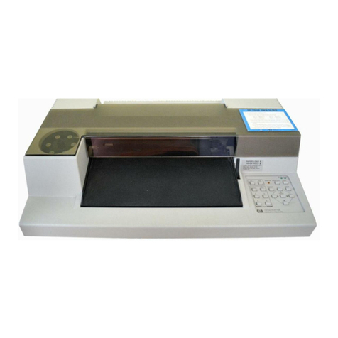
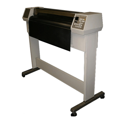
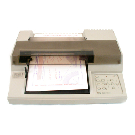
HP 7470A Owner's manual

INTERFACING
AND
PROGRAMMING
MANUAL
HP 7470A
Graphics Plotter
RS 232 C/CCITT V24
DESIGNED FOR
SYSTEMS

The United States Federal Communications Commission
(in 47CFR 15.838)has specified that the following notice
be brought to the attention of users ofthis product.
FEDERAL COMMUNICATIONS COMMISSION
RADIO FREQUENCY INTERFERENCE
STATEMENT
“Thisequipmentgeneratesand usesradiofrequencyenergyand
ifnot installed and used properly, that is, instrict accordance with
the manufacturer's instructions, maycause interference to radio
and television reception. it has been type tested and found to
comply with the limits for a Class B computing device in
accordance withthe specifications inSubpart J of Part 15of FCC
Rules, which are designed to provide reasonable protection
against such interference in a residential installation. However.
there is no guarantee that interference will not occur in a
particular installation. lfthis equipment does cause interference
to radio or television reception, which can be determined by
turningtheequipmentoffand on,the useris encouragedtotryto
correct the interference by one or more of the following
measures:
—reorient the receiving antenna
—relocate the computer with respect to the receiver
—move the computer away from the receiver
—plug the computer into a different outlet so that computer and
receiver are on different branch circuits.
Ifnecessary, the user should consult the dealer or an experienced
radio/television technician for additional suggestions. The user
may find the following booklet prepared by the Federal Com
munications Commission helpful:
‘Howto Identify and Resolve Radio TV Interference Problems‘.
This booklet isavailable from the USGovernment Printing Office,
Washington, DC 20402, Stock No. 004 000 00345 4."

INTERFA(§1\1\JIG 1C:1PpZ_47%;\tt
D ra 1cs 0 er
PROGRAMMING
M RS 232 C/CCITTV.24
ossncnmran
SYSTEMS
W
@1982,1984, by Hewlett Packard Comp
16399W. Bernardo Drive, San Diego, CA 92 1899

Manual Summary
Chapter 1: Getting Started
Contains information concerning manual usage, a description of the
plotter, its interfaces, the HP—GLlanguage, and three instructions.
Chapter 2: Establishing Boundaries and Units
Explains the concept of plotting area, plotter and user units, scaling,
and the instructions used to set and output the scaling points and
window, and to scale the plotting area.
Chapter 3: Controlling the Pen and Plotting
Describesthe instructions for pen control and vector plotting.
Chapter 4: Enhancing the Plot
Describesinstructions for drawing tick marks and differentiating traces.
Chapter 5: Labeling
Describes the instructions used in labeling to set direction, size, and
slant of characters, as well as instructions for character set and label
terminator selection and for designing your own characters.
Chapter 6: Digitizing
Describes the instructions used to digitize with the plotter and demon
strates how to check for the presence of a digitized point.
Chapter 7: Obtaining Information fromthe Plotter
Describes the instructions used to obtain information about pen posi
tion, errors, and capabilities ofthe plotter.
Chapter 8: Putting the Commandsto Work
A step by—stepexample illustrating the procedures to be followed to
draw labels and plot data using HP GLinstructions.
Chapter 9: HP IB Interfacing
Summarizes operation ofthe plotter with the Hewlett PackardInterface
Bus (HP IB)and explains the methods for addressing and sending and
receiving data over the interface bus.
Chapter 10: RS 232 C/CCITT V.24Interfacing
Describes how to connect the plotter with a terminal and/ or computer,
summarizes the methods for establishing a handshake protocol be
tween the plotter and computer, and explains the devicecontrol instruc
tions that are used to set up and control the handshake protocol.
Chapter 11: HP IL Interfacing .
Describesthe Hewlett Packard Interface Loop(HP IL)and explains the
methods for sending and receiving data overthe interface loop.
Appendix A: An HP IB Overview
Provides an overview of the Hewlett Packard Interface Bus (HP IB).
ii MANUAL SUMMARY

Manual Summary (Continued)
AppendixB: Instruction Syntax
Provides a summary of both HP—GLand device control instructions.
Appendix C: Reference Material
Includes a summary of default conditions, error messages, scaling
equations, NOP instructions, ASCII codes, and character sets.
MANUAL SUMMARY iii

Tableof Contents
Chapter 1: Getting Started . . . . . . . . . . . . . . . . . . . . . . . . . . . . . . . . . . . . 1 1
What You’ll Learn in This Chapter . . . . . . . . . . . . . . . . . . . . . . . . . . . 1 1
HP GL Instructions Covered . . . . . . . . . . . . . . . . . . . . . . . . . . . . . . . 1 1
Terms You Should Understand . . . . . . . . . . . . . . . . . . . . . . . . . . . . . 1 1
How to Use HP 7470 Documentation . . . . . . . . . . . . . . . . . . . . . . . . . 1 2
For First Encounters with the 7470 . . . . . . . . . . . . . . . . . . . . . . . . . 1 3
For First Encounters with HP GL . . . . . . . . . . . . . . . . . . . . . . . . . . 1 3
For Experienced HP GL Programmers . . . . . . . . . . . . . . . . . . . . . 1 3
Understanding Manual Conventions and Syntax . . . . . . . . . . . 1 3
A Brief Look at the 7470 Plotter . . . . . . . . . . . . . . . . . . . . . . . . . . . . . . 1 5
The 7470 Plotter’s Instruction Set . . . . . . . . . . .‘. . . . . . . . . . . . . . . . . 1 6
HP GL Syntax . . . . . . . . . . . . . . . . . . . . . . . . . . . . . . . . . . . . . . . . . . . . . . 1 6
How to Use the Examples in This Manual . . . . . . . . . . . . . . . . . . . . 1 10
The Default Instruction, DF . . . . . . . . . . . . . . . . . . . . . . . . . . . . . . . . . 1 10
The Initialize Instruction, IN . . . . . . . . . . . . . . . . . . . . . . . . . . . . . . . . 1 11
The Input Mask Instruction, IM . . . . . . . . . . . . . . . . . . . . . . . . . . . . . 1 12
Looking Ahead . . . . . . . . . . . . . . . . . . . . . . . . . . . . . . . . . . . . . . . . . . . . . 1 15
Chapter 2: Establishing Boundaries and Units . . . . . . . . . . . . . . . . . 2 1
What You’ll Learn in This Chapter . . . . . . . . . . . . . . . . . . . . . . . . . . . 2 1
HP GL Instructions Covered . . . . . . . . . . . . . . . . . . . . . . . . . . . . . . . 2 1
Terms You Should Understand . . . . . . . . . . . . . . . . . . . . . . . . . . . . . 2 1
The Plotting Area . . . . . . . . . . . . . . . . . . . . . . . . . . . . . . . . . . . . . . . . . . . 2 2
Unit Systems . . . . . . . . . . . . . . . . . . . . . . . . . . . . . . . . . . . . . . . . . . . . . . . 2 3
The Plotter Unit . . . . . . . . . . . . . . . . . . . . . . . . . . . . . . . . . . . . . . . . . . 2 3
User Units . . . . . . . . . . . . . . . . . . . . . . . . . . . . . . . . . . . . . . . . . . . . . . . 2 3
Setting the Scaling Points . . . . . . . . . . . . . . . . . . . . . . . . . . . . . . . . . . . 2 3
Setting P1 and P2 Manually . . . . . . . . . . . . . . . . . . . . . . . . . . . . . . . 2 4
The Input P1 and P2 Instruction, IP . . . . . . . . . . . . . . . . . . . . . . . . . . 2 4
The Output P1 and P2 Instruction, OP . . . . . . . . . . . . . . . . . . . . . . . 2 5
The Scale Instruction, SC . . . . . . . . . . . . . . . . . . . . . . . . . . . . . . . . . . . . 2 6
The Input Window Instruction, IW . . . . . . . . . . . . . . . . . . . . . . . . . . . 2 9
The Output Window Instruction, OW . . . . . . . . . . . . . . . . . . . . . . . . . 2 10
Advanced Programming Tips . . . . . . . . . . . . . . . . . . . . . . . . . . . . . . . . 2 11
Chapter 3: Controlling the Pen and Plotting . . . . . . . . . . . . . . . . . . . . 3 1
What You’ll Learn in This Chapter . . . . . . . . . . . . . . . . . . . . . . . . . . . 3 1
HP GL Instructions Covered . . . . . . . . . . . . . . . . . . . . . . . . . . . . . . . 3 1
Terms You Should Understand . . . . . . . . . . . . . . . . . . . . . . . . . . . . . 3 1
1V TABLE OF CONTENTS

Table of Contents (Continued)
Chapter 3: Controlling the Pen and Plotting (Continued)
The Pen Instructions, PU and PD . . . . . . . . . . . . . . . . . . . . . . . . . . . . 3 2
The Select Pen Instruction, SP . . . . . . . . . . . . . . . . . . . . . . . . . . . . . . . 3 2
The Velocity Select Instruction, VS . . . . . . . . . . . . . . . . . . . . . . . . . . . 3 3
The Plot Absolute Instruction, PA . . . . . . . . . . . . . . . . . . . . . . . . . . . . 3 4
The Plot Relative Instruction, PR . . . . . . . . . . . . . . . . . . . . . . . . . . . . 3 8
Plotting with Variables . . . . . . . . . . . . . . . . . . . . . . . . . . . . . . . . . . . . . . 3 11
The Circle Instruction, CI . . . . . . . . . . . . . . . . . . . . . . . . . . . . . . . . . . . 3 12
The Arc Absolute Instruction, AA . . . . . . . . . . . . . . . . . . . . . . . . . . . . 3 17
The Arc Relative Instruction, AR . . . . . . . . . . . . . . . . . . . . . . . . . . . . 3 19
Chapter 4: Enhancing the Plot . . . . . . . . . . . . . . . . . . . . . . . . . . . . . . . . 4 1
What You’ll Learn in This Chapter . . . . . . . . . . . . . . . . . . . . . . . . . . . 4 1
HP GL Instructions Covered . . . . . . . . . . . . . . . . . . . . . . . . . . . . . . . 4 1
The Tick Instructions, XT and YT . . . . . . . . . . . . . . . . . . . . . . . . . . . . 4 2
The Tick Length Instruction, TL . . . . . . . ._. . . . . . . . . . . . . . . . . . . . . 4 2
The Symbol Mode Instruction, SM . . . . . . . . . . . . . . . . . . . . . . . . . . . 4 4
The Line Type Instruction, LT . . . . . . . . . . . . . . . . . . . . . . . . . . . . . . . 4 6
Chapter 5: Labeling . . . . . . . . . . . . . . . . . . . . . . . . . . . . . . . . . . . . . . . . . . 5 1
What You’ll Learn in This Chapter . . . . . . . . . . . . . . . . . . . . . . . . . . . 5 1
HP GL Instructions Covered . . . . . . . . . . . . . . . . . . . . . . . . . . . . . . . 5 1
Terms You Should Understand . . . . . . . . . . . . . . . . . . . . . . . . . . . . . 5 1
Plotter Character Sets . . . . . . . . . . . . . . . . . . . . . . . . . . . . . . . . . . . . . . . 5 2
The Designate Standard Character Set Instruction, CS . . . . . . . . 5 3
The Designate Alternate Character Set Instruction, CA . . . . . . . . 5 4
The Select Standard Set Instruction, SS . . . . . . . . . . . . . . . . . . . . . . 5 4
The Select Alternate Set Instruction, SA . . . . . . . . . . . . . . . . . . . . . . 5 5
The Define Terminator Instruction, DT . . . . . . . . . . . . . . . . . . . . . . . 5 6
The Label Instruction, LB . . . . . . . . . . . . . . . . . . . . . . . . . . . . . . . . . . . 5 7
Labeling with Variables . . . . . . . . . . . . . . . . . . . . . . . . . . . . . . . . . . . . . 5 9
The Absolute Direction Instruction, DI . . . . . . . . . . . . . . . . . . . . . . . 5 10
The Relative Direction Instruction, DR . . . . . . . . . . . . . . . . . . . . . . . 5 11
Spacing Between Characters . . . . . . . . . . . . . . . . . . . . . . . . . . . . . . . . 5 12
The Character Plot Instruction, CP . . . . . . . . . . . . . . . . . . . . . . . . . . 5 13
The Absolute Character Size Instruction, SI . . . . . . . . . . . . . . . . . . 5 15
The Relative Character Size Instruction, SR . . . . . . . . . . . . . . . . . . 5 16
The Character Slant Instruction, SL . . . . . . . . . . . . . . . . . . . . . . . . . 5 18
TABLE OF CONTENTS V
Table of Contents (Continued)
Chapter 5: Labeling (Continued)
The User Defined Character Instruction, UC . . . . . . . . . . . . . . . . . . 5 19
Parameter Interaction in Labeling Commands . . . . . . . . . . . . . . . . 5 21
Advanced Programming Tips . . . . . . . . . . . . . . . . . . . . . . . . . . . . . . . . 5 27
Chapter 6: Digitizing . . . . . . . . . . . . . . . . . . . . . . . . . . . . . . . . . . . . . . . .. 6 1
What You’ll Learn in This Chapter . . . . . . . . . . . . . . . . . . . . . . . . . . . 6 1
HP—GL Instructions Covered . . . . . . . . . . . . . . . . . . . . . . . . . . . . . . . 6 1
Terms You Should Understand . . . . . . . . . . . . . . . . . . . . . . . . . . . . . 6 1
Preparing Your Plotter for Use as a Digitizer . . . . . . . . . . . . . . . . . . 6 2
The Digitize Point Instruction, DP . . . . . . . . . . . . . . . . . . . . . . . . . 6 2
The Digitize Clear Instruction, DC . . . . . . . . . . . . . . . . . . . . . . . . . . . 6 3 A
The Output Digitized Point and Pen Status Instruction, OD . . . . . 6 3
Digitizing with the 7470 . . . . . . . . . . . . . . . . . . . . . . . . . . . . . . . . . . . . . 6 4
Manual Method . . . . . . . . . . . . . . . . . . . . . . . . . . . . . . . . . . . . . . . . . . . 6 4
Monitoring the Status Byte . . . . . . . . . . . . . . . . . . . . . . . . . . . . . . . . 6 5
HP—IB Interrupts and Polling . . . . . . . . . . . . . . . . . . . . . . . . . . . . . . 6 7
Chapter 7: Obtaining Information From the Plotter . . . . . . . . . . . . . 7 1
What You’ll Learn in This Chapter . . . . . . . . . . . . . . . . . . . . . . . . . . . 7 1
HP—GL Instructions Covered . . . . . . . . . . . . . . . . . . . . . . . . . . . . . . . 7 1
Terms You Should Understand . . . . . . . . . . . . . . . . . . . . . . . . . . . . . 7 1
A Brief Word about Plotter Output . . . . . . . . . . . . . . . . . . . . . . . . . . . 7 2
Notes for an HP IB User . . . . . . . . . . . . . . . . . . . . . . . . . . . . . . . . . . 7 2
Notes for an RS 232 C User . . . . . . . . . . . . . . . . . . . . . . . . . . . . . . . . 7 2
Notes for an HP IL User . . . . . . . . . . . . . . . . . . . . . . . . . . . . . . . . . . 7 2
The Output Actual Position and Pen Status
Instruction, OA . . . . . . . . . . . . . . . . . . . . . . . . . . . . . . . . . . . . . . . . . . . 7 3
The Output Commanded Position and Pen Status
Instruction, OC . . . . . . . . . . . . . . . . . . . . . . . . . . . . . . . . . . . . . . . . . . . 7 4
The Output Error Instruction, OE . . . . . . . . . . . . . . . . . . . . . . . . . . . . 7 5
The Output Factors Instruction, OF . . . . . . . . . . . . . . . . . . . . . . . . . . 7 6
The Output Identification Instruction, OI . . . . . . . . . . . . . . . . . . . . . 7 7
The Output Options Instruction, OO . . . . . . . . . . . . . . . . . . . . . . . . . 7 7
The Output Status Instruction, OS . . . . . . . . . . . . . . . . . . . . . . . . . . . 7 8
Summary of Output Response Types . . . . . . . . . . . . . . . . . . . . . . . . . 7 9
Vi TABLE OF CONTENTS

Table of Contents (Continued)
Chapter 8: Putting the Commands to Work . . . . . . . . . . . . . . . . . . . . . 8 1
What You’ll Learn in This Chapter . . . . . . . . . . . . . . . . . . . . . . . . . . . 8 1
Problem .................................................... 82
Solution . . . . . . . . . . . . . . . . . . . . . . . . . . . . . . . . . . . . . . . . . . . . . . . . . . . . 8 2
Setup and Scaling . . . . . . . . . . . . . . . . . . . . . . . . . . . . . . . . . . . . . . . . 8 2
The Axes and Their Labels . . . . . . . . . . . . . . . . . . . . . . . . . . . . . . . . 8 3
Adding Color and Emphasis . . . . . . . . . . . . . . . . . . . . . . . . . . . . . . . 8 5
Plotting Your Data . . . . . . . . . . . . . . . . . . . . . . . . . . . . . . . . . . . . . . . . 8 6
Listing . . . . . . . . . . . . . . . . . . . . . . . . . . . . . . . . . . . . . . . . . . . . . . . . . . . . . 8 9
Advanced Programming Tips . . . . . . . . . . . . . . . . . . . . . . . . . . . . . . . . 8 10
Filling and Hatching . . . . . . . . . . . . . . . . . . . . . . . . . . . . . . . . . . . . . . 8 10
Filling a Bar . . . . . . . . . . . . . . . . . . . . . . . . . . . . . . . . . . . . . . . . . . . . . 8 10
Hatching a Bar . . . . . . . . . . . . . . . . . . . . . . . . . . . . . . . . . . . . . . . . . . . 8 12
Filling Segments of Pie Charts . . . . . . . . . . . . . . . . . . . . . . . . . . . . . 8 13
Chapter 9: HP IB Interfacing . . . . . . . . . . . . . . . . . . . . . . . . . . . . . . . . . . 9 1
What You’ll Learn in This Chapter . . . . . . . . . . . . . . . . . . . . . . . . . . . 9 1
HP IB Implementation on the 7470 . . . . . . . . . . . . . . . . . . . . . . . . . . . 9 2
Interface Switches and Controls . . . . . . . . . . . . . . . . . . . . . . . . . . . . . 9 2
Addressing the Plotter . . . . . . . . . . . . . . . . . . . . . . . . . . . . . . . . . . . . 9 2
Bus Commands . . . . . . . . . . . . . . . . . . . . . . . . . . . . . , . . . . . . . . . . . . . . . 9 4
Reaction to Bus Commands DCL, SDC, and IFC . . . . . . . . . . . . 9 4
Serial and Parallel Polling . . . . . . . . . . . . . . . . . . . . . . . . . . . . . . . . . 9 4
Addressing the 7470 as a Talker or Listener . . . . . . . . . . . . . . . . . . . 9 6
Computers with No High Level I/O Statements . . . . . . . . . . . . . 9 6
Computer with High Level I/O Statements . . . . . . . . . . . . . . . . . 9 6
Sending and Receiving Data . . . . . . . . . . . . . . . . . . . . . . . . . . . . . . . . . 9 7
Computer to Plotter . . . . . . . . . . . . . . . . . . . . . . . . . . . . . . . . . . . . . . . 9 7
Plotter to—Computer . . . . . . . . . . . . . . . . . . . . . . . . . . . . . . . . . . . . . . . 9 10
Chapter 10: RS 232 C/CCITT V.24 Interfacing . . . . . . . . . . . . . . . . . . 10 1
What You’ll Learn in This Chapter . . . . . . . . . . . . . . . . . . . . . . . . . . . 10 1
Setting Up Your RS 232—CPlotter: a Checklist . . . . . . . . . . . . . . . . 10 2
Plotter Environments . . . . . . . . . . . . . . . . . . . . . . . . . . . . . . . . . . . . . . . 10 2
Using a Plotter Directly Connected to a
Computer Mainframe or Personal Computer . . . . . . . . . . . . . . 10 2
Using a Plotter in an Environment with a Terminal . . . . . . . . . 10 4
Using the Plotter in a Terminal only Environment . . . . . . . . . . 10 9
Connecting the RS 232 C Interface . . . . . . . . . . . . . . . . . . . . . . . . . . . 10 10
TABLE OF CONTENTS Vii

Table of Contents (Continued)
Chapter 10: RS 232 C/CCITT V.24Interfacing (Continued)
Output Baud Rate . . . . . . . . . . . . . . . . . . . . . . . . . . . . . . . . . . . . . . . . . . 10 12
Stop Bits . . . . . . . . . . . . . . . . . . . . . . . . . . . . . . . . . . . . . . . . . . . . . . . . . . . 10 13
Transmission Errors . . . . . . . . . . . . . . . . . . . . . . . . . . . . . . . . . . . . . . . . 10 13
Handshaking . . . . . . . . . . . . . . . . . . . . . . . . . . . . . . . . . . . . . . . . . . . . . . .10 14
Software Checking . . . . . . . . . . . . . . . . . . . . . . . . . . . . . . . . . . . . . . . . 10 17
Xon Xoff Handshake . . . . . . . . . . . . . . . . . . . . . . . . . . . . . . . . . . . . . .10 19
Enquire/Acknowledge Handshake . . . . . . . . . . . . . . . . . . . . . . . . . 10 20
Hardwire Handshake . . . . . . . . . . . . . . . . . . . . . . . . . . . . . . . . . . . . . 10 22
RS 232 C Device Control Instructions . . . . . . . . . . . . . . . . . . . . . . . . . 10 22
Command Syntax for Device Control Instructions . . . . . . . . . . .10 23
The Plotter On Instruction, ESC . ( or ESC . Y . . . . . . . . . . . . . . .10 24
The Plotter Off Instruction, ESC . ) or ESC . Z . . . . . . . . . . . . . . . . 10 24
The Set Plotter Configuration Instruction, ESC . @ . . . . . . . . . . . .10 25
The Output Buffer Space Instruction, ESC . B . . . . . . . . . . . . . . . . 10 26
The Output Extended Error Instruction, ESC . E . . . . . . . . . . . . . .10 27
The Set Handshake Mode 1 Instruction, ESC . H . . . . . . . . . . . . . .10 28
The Set Handshake Mode 2 Instruction, ESC . I . . . . . . . . . . . . . . .10 29
The Abort Device Control Instruction, ESC . J . . . . . . . . . . . . . . . . 10 31
The Abort Graphic Instruction, ESC . K . . . . . . . . . . . . . . . . . . . . . . 10 32
The Output Buffer Size Instruction, ESC . L . . . . . . . . . . . . . . . . . . 10 32
The Set Output Mode Instruction, ESC . M . . . . . . . . . . . . . . . . . . .10 33
The Set Extended Output and Handshake Mode
Instruction, ESC . N . . . . . . . . . . . . . . . . . . . . . . . . . . . . . . . . . . . . . . 10 34
The Output Extended Status Instruction, ESC . O . . . . . . . . . . . . .10 38
The Reset Handshake Instruction, ESC . R . . . . . . . . . . . . . . . . . . . 10 40
Chapter 11: HP IL Interfacing . . . . . . . . . . . . . . . . . . . . . . . . . . . . . . . . . 11 1
What You’ll Learn in this Chapter . . . . . . . . . . . . . . . . . . . . . . . . . . . 11 1
An Overview of HP IL . . . . . . . . . . . . . . . . . . . . . . . . . . . . . . . . . . . . . . 11 1
HP IL Implementation on the 7470 . . . . . . . . . . . . . . . . . . . . . . . . . . . 11 2
Reaction to Interface Commands and Messages . . . . . . . . . . . . . . . 11 3
Addressing the Plotter , . . . . . . . . . . . . . . . . . . . . . . . . . . . . . . . . . . . . . 11 3
Sending and Receiving Data . . . . . . . . . . . . . . . . . . . . . . . . . . . . . . . . . 11 4
Computer to—P1otter . . . . . . . . . . . . . . . . . . . . . . . . . . . . . . . . . . . . . . . 11 4
Plotter to Computer . . . . . . . . . . . . . . . . . . . . . . . . . . . . . . . . . . . . . . . 11 5
viii TABLEOF CONTENTS

Table of Contents (Continued)
Appendix A: An HP—IB Overview . . . . . . . . . . . . . . . . . . . . . . . . . . . . . . A 1
HP—IB System Terms . . . . . . . . . . . . . . . . . . . . . . . . . . . . . . . . . . . . . . A 1
Interface Bus Concepts . . . . . . . . . . . . . . . . . . . . . . . . . . . . . . . . . . . . A 1
Message Concepts . . . . . . . . . . . . . . . . . . . . . . . . . . . . . . . . . . . . . . . . A 2
The HP Interface Bus . . . . . . . . . . . . . . . . . . . . . . . . . . . . . . . . . . . . . . . A 4
HP—IB Lines and Operations . . . . . . . . . . . . . . . . . . . . . . . . . . . . . . . A 4
Interface Functions . . . . . . . . . . . . . . . . . . . . . . . . . . . . . . . . . . . . . . . A 7
Bus Messages . . . . . . . . . . . . . . . . . . . . . . . . . . . . . . . . . . . . . . . . . . . . A 8
Appendix B: Instruction Syntax . . . . . . . . . . . . . . . . . . . . . . . . . . . . . . . B 1
HP GL Syntax . . . . . . . . . . . . . . . . . . . . . . . . . . . . . . . . . . . . . . . . . . . . . . B 1
RS 232 C Instruction Syntax . . . . . . . . . . . . . . . . . . . . . . . . . . . . . . . . . B 12
Appendix C: Reference Material . . . . . . . . . . . . . . . . . . . . . . . . . . . . . . . C 1
Binary Coding and Conversions . . . . . . . . . . . . . . . . . . . . . . . . . . . . . C 1
Binary Decimal Conversions . . . . . . . . . . . . . . . . . . . . . . . . . . . . . . . . C 1
Scaling Without Using the SC Instruction . . . . . . . . . . . . . . . . . . . . C 2
Plotter Default Conditions . . . . . . . . . . . . . . . . . . . . . . . . . . . . . . . . . . . C 5
HP GL Error Messages . . . . . . . . . . . . . . . . . . . . . . . . . . . . . . . . . . . . . . C 6
RS 232 C Error Messages . . . . . . . . . . . . . . . . . . . . . . . . . . . . . . . . . . . . C 6
The No Operation Instructions, NOP . . . . . . . . . . . . . . . . . . . . . . . . . C '7
ASCII Character Codes . . . . . . . . . . . . . . . . . . . . . . . . . . . . . . . . . . . . . C 7
Subject Index . . . . . . . . . . . . . . . . . . . . . . . . . . . . . . . . . . . . . . . . . . . . . . . . . SI—1
TABLE OF CONTENTS ix

Notes

Chapter1
Getting Started
What You’llLearn in This Chapter
In this chapter you willlearn what is coveredin this manual and what
other manuals you may need or find useful. In addition, this chapter
contains a description of the plotter and its three available interfaces.
The plotter’s language and its syntax are described. A table is given
showing all the HP GL instructions implemented in the 7470. At the
end of the chapter, three instructions from the plotter’s language, HP~GL
(Hewlett—PackardGraphics Language) are described.
HP GLInstructions Covered
DF The Default Instruction
IN The Initialize Instruction
IM The Input Mask Instruction
Terms YouShould Understand
HP GL — Hewlett Packard Graphics Language — the two letter
mnemonic graphics language understood by the 7470Plotter and other
HP graphics devices. The instruction’s mnemonic is suggestive of its
role. For instance, PAis used to plot to absolute coordinates, SP is used
to select a pen, and DR is used to establish the relative direction of
labeling.
HP IB — Hewlett Packard Interface Bus — HP’s implementation of
IEEE standard 488 1978digital interface for programmable instru
mentation, commonly found on HP desktop computers, and some
larger computers. The HP—IBinterface is standard on the Option 002
plotter.
RS 232—C/CCITTV24 Interface —another popular standardized inter
face. It is commonly found on large computers, personal computers,
and in environments where communication over telephone lines is
required. The RS—232—C/CCITTV.24 interface is standard on the Op
tion 001 plotter.
GETTING STARTED 1 1

HP—IL— Hewlett—Packard Interface Loop — an interface used on some
Hewlett—Packardpersonal computing products to communicate with
peripheral devices such as the 7470 plotter. The HP IL interface is
standard on the Option 003plotter.
How to Use HP 7470 Documentation
This manual contains interfacing and programming information for
the HP 7470 Plotter and all its interfacing options. The Option 001
plotter is equipped with the RS—232—C/CCITTV.24Interface. The Option
002 plotter is interfaced through the Hewlett—PackardInterface Bus
(HP—IB)which conforms to ANSI/IEEE 488 1978 specifications. The
Option 003 plotter is equipped with the Hewlett Packard Interface Loop
for personal computing devices. All interfaces use the Hewlett Packard
Graphics Language (HP—GL)for control of plotter graphics capabilities.
Unless specifically noted, all information in this manual pertains to all
configurations.
NOTE: All information in this manual for Option 001 plotters applies
equally to RS—232—Cand CCITT V.24 interfaces. For purposes of sim
plicity, both are referred to as RS 232—C.I
Documentation for this plotter is designed to enable you to use the
plotter easily without reading unnecessary manuals. All plotters are
shipped with this manual, an Operator’s Manual (Part No. 07470
90002), an Interconnection Guide (07470 90003),and a Reference Card
(07470 90004).The Operator’s Manual contains all information you will
need to operate, but not program, the plotter. The Interconnect Guide
explains how to physically connect your plotter to certain computers or
calculators, and contains instructions for verifying that the connection
has been made. The Reference Card contains a list of the plotter’s HP
GL instructions with their parameters, its device control instructions
for the RS—232—Cversion, and a list of error numbers and their meanings.
1 2 GETTING STARTED

For First Encounters with the 7470
If you have just received your HP 7470, read the Operator’s Manual
and the Interconnection Guidebeforeattempting to operate the plotter.
After inspecting your plotter, its power cord, and accessories as
described in the Operator’s Manual, refer to the appropriate chapter of
this manual for initial setup and addressing or handshaking protocol
for your configuration. RS 232—Cusers should read Chapter 10, HP—IB
users should read Chapter 9, and HP—ILusers should read Chapter 11.
For First Encounters with HP GL
If you have never programmed in HP GL,after reading the interfacing
chapter, read Chapters 1 through 5 in order. These chapters describe
the instructions you will use in almost every application. Running the
examples given with the instructions will help you learn. Next, read
Chapter 8 to see how all the instructions work together in a program.
When you have an application requiring digitizing or plotter output,
read Chapters 6 and 7.
For Experienced HP GLProgrammers
If you are an experienced HP GL programmer, you may find Appendix
B of this manual or the Reference Card most helpful. Since there are
Idifferences in syntax between this and other plotters, you should read
Chapter 1 of this manual before programming. The 7470 has added
capabilities not found in earlier plotters. Among these are the ability to
plot to non—integeruser—unitvalues, to mirror labels using negative size
and direction parameters, and to output the current window values. To
understand these differences, you need to read the sections on scaling
(SC, Chapter 2);plotting (PAand PR, Chapter 3),and setting label size
and direction in Chapter 5. In the instruction set summary in Appendix
B, page numbers for the complete description are listed with each
instruction.
Understanding Manual Conventions and Syntax
Before reading any part of this manual, you should understand the
meaning of type styles, symbols, and number representation used in
text. A detailed explanation of syntax symbols is given in the section
entitled HP GL Syntax in this chapter and Command Syntax for
Device Control Instructions in Chapter 10. The following conventions
also apply. Words typed in small boldface type are either buttons,
switches, or words actually found on the plotter or computer. Headings
in typeareusedtohelplocatespecificpartsofthewriteupof
an instruction. type in a smaller size is used to denote a single
ASCII character which should be sent to the plotter. Numbers are
typed using SI (International System of Units) standards; numbers
with more than four digits are placed in groups of three, separated by a
GETTING STARTED I 3

space instead of commas, counting both to the left and right of the
decimal point (54 321.123 45).
Followthe documentation road map below:
ALL USERS
OPERATOR'S
MANUAL
07470 90002
I
INTERCONNECTION
GUIDE
07470 90003
RS 232 C USER HP IB, HP IL
USERS
INTERFACING AND ‘L
PROGRAMMING
MANUAL,
CHAPTER 10
07470 90001
>
4 t
V
USER OF SOFTWARE GRAPHICS ROM USER HP GL PROGRAMMER
PACKAGE
INTERFACING AND
PROGRAMMING
YOUR GRAPHICS ROM MANUAL
SOFTWARE MANUAL MANUAL o747o.9ooo1
CHAPTERS 1 8, AND
CHAPTER 9, 10, OR 11
1 4 GETTING STARTED

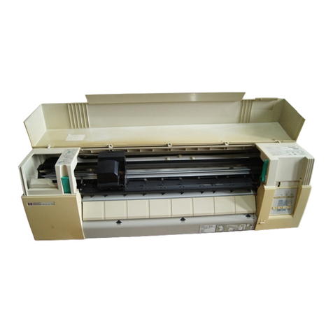
ABrief Look at the 7470Plotter
The HP 7470Graphics Plotter is a vector plotter which produces high
quality, multicolor graphics plots on two sizes of drawing media:
English ANSI A (81/2X 11 in.) or metric ISO A4 (210 X 297 mm). With
programmable pen velocity and a choiceof standard fiber tip or trans
parency pens, the 7470 can produce distinctive graphics not only on
standard paper, but also on other media such as transparency film.
The plotter offers both fast plotting speed and high line quality,
achieved using Hewlett—Packard’smicro grip drive technology. This
technology provides low—inertiagrit—coveredwheels to move the paper
in one axis while the pen moves along the other axis. Plotting occurs
with approximately 2 g acceleration and a maximum velocity of 38.1
cm/s (15in./ s).The result is exceptional line and character quality and
high throughput. The 7470 has addressable resolution of 0.025 mm
(0.001in.) and repeatability of 0.10 mm (0.004in.) for any given pen.
The multicolor graphics capability is provided by programmed or front
panel selection of two pens. If additional colors are desired, the pro
gram can be paused to allow manual installation of additional pens.
Seven different dashed—linefonts and symbol mode plotting provide
additional trace identification capabilities.
Character plotting speed of up to six characters per second enables you
to produce fully—letteredgraphs quickly. Annotation can be easily done
using any of five character sets, including three European sets. Text
can be written in any direction, with or without character slant, and in
varying sizes. ’
The 7470is engineered to be especially useful in the areas of business
graphics, statistics, medicine, numerical control, surveying, and engi
neering design. An optional overhead transparency kit enables you to
produce high quality graphic transparencies from your plotting pro
grams. For faster comprehension, you can present economic trends,
engineering or scientific data, marketing plans, profit data, or sales
forecasts pictorially. And with a choice of media, you can create paper
hardcopy for an individual’s attention or transparencies for group
presentations.
Whether data are tabulated, measured, or computed, depend on the
reliable 7470to prepare multicolored plots of excellent line quality and
high resolution.
GETTING STARTED 1 5

The 7470 P1otter’s Instruction Set
All three interface configurations for the HP 7470Plotter use the same
Hewlett Packard Graphics Language (HP—GL)instruction set, with
minor exceptions.* HP—GLconsists of two letter mnemonic instructions
which activate the plotter. A table listing the instructions alphabetically
is located at the end of the next section. Syntax descriptions and
explanations ofthese instructions are contained in Chapters 1through
8. Six additional HP—GLinstructions cause no operation but are in
cluded for compatibility with other HP plotters. These instructions are
listed in Appendix C.
Fourteen additional instructions, called device control instructions, are
required by the RS 232 Cconfiguration. These instructions are used to
establish plotter output and handshake protocol,and to control condi
tions which are pertinent only to the RS 232 Cenvironment. In an
RS 232 C plotter, all HP—GLinstructions enter the p1otter’s internal
buffer and are executed in a first—in,first—outsequence. Device control
instructions do not enter the buffer, but instead are executed imme
diately upon receipt. Referto Chapter 10for the syntax description and
an explanation ofthe devicecontrol instructions.
HP—GLSyntax
An HP—GLinstruction is a two letter mnemonic, which may be upper
or lowercase. A command is defined as an instruction followed by its
parameter field, if any, and a terminator. If parameters follow the
mnemonic, they must be separated from each other by at least one
comma or space, or by a + or sign which may be preceded by commas
or spaces. Optional commas and/ or spaces may be used as separators
before, after, and between the mnemonic and before the terminator. An
instruction is terminated by a semicolon, nonalphabetic and nonnu
meric characters such as # or $, or by the next mnemonic. If you have
an HP—IBor HP—ILplotter, a line feed can also terminate an instruction.
(Note that if you have an RS 232 Cplotter, a line feed is not a valid
terminator.) Some instructions will execute immediately after the
mnemonic or last required parameter is received. When this is the case,
the designation for the terminator is shown in parentheses in the
syntax description. The syntax is shown on the next page.
*Option 001 provides 45 instructions; Option 002 provides 42 instructions;
Option 003 provides 41 instructions. Refer to the Plotter Instruction Set table
in this chapter.
1 6 GETTING STARTED

INSTRUCTION PARAMETER FIELD
MNEMONIC (As REQUIRED) (AS REQUIRED)
: ‘—i I
Sep X Sep X Sep Parameter Sep Parameter Sep Terminator
TTTI T
OPTIONAL SEPARATORS REQUIRED SEPARATOR
(0 OR MORE COMMAS
ANDIOR SPACES)
NOTE: The syntax implemented on the 7470is extremely flexible and
differs from that used on other Hewlett—Packardplotters such as»the
HP 9872.Therefore, any software written for the 7470which takes ad
vantage of its less rigorous syntax will not be able to drive most other
HP plotters. If software is to be used with other HP GL plotters, the
more rigorous syntax ofthe HP 9872plotter should be used.
XXParameters (,Parameters) Terminator
INSTRUCTION: 2; FORRS 232 CPLOTTERS
;OR LF FOR HP—IBOR
HP IL PLOTTERS
OPTIONAL PARAMETERS
The 9872 syntax does not allow separators between the characters of
the mnemonic. One comma must separate parameters. Only; or LF
may be used as the terminator for HP—IBor HP—ILplotters, and only ;
may be used as the terminator for RS—232—Cplotters. In addition, pa
rameters requiring integer format may not contain a decimal point or
decimalfraction. I
Some instructions have optional parameters which, when omitted,
assume a default value. In order to omit a parameter, all subsequent
parameters in the same instruction must be omitted. The only excep
tion is the pen parameters in the HP GLinstruction, UC.
The label instruction, LB, is a special case; it must be terminated with
the label terminator character. This character defaults to the ASCII
end of text character, ETX, whose decimal equivalent is 3. The label
terminator may be changed from its default value using the define
terminator instruction, DT.
The parameter fields must be specified in the format defined by the
syntax of each respective HP GL instruction. The format can be of
three types:
1. Integer Format —a parameter in integer format between 32 768.0000
and +32 767.9999.Decimal fractions of parameters which must be
integers are truncated. If no sign is specified, the parameter is
assumed to be positive.
GETTING STARTED 1 7

2. Decimal Format — a number between —128.0000and 1279999 with
an optional decimal point and decimal fraction with up to four
significant digits. If no sign is specified,the parameter is assumed to
be positive.
3. Label Fields — any combination of text, numeric expressions, or
string variables. Refer to The Label Instruction, LB, Chapter 5,for a
complete description.
Some instructions such as PA, PR, PU, and PD may have multiple
parameters. Separators are required between these parameters. These
optional parameters are shown in parentheses in the syntax descriptions.
The syntax shown under the description of each HP GL instruction
uses the following notations:
MNemonic
necessary parameter
( )
C....C
(,. )
terminator
(terminator)
For readability, the mnemonic is shown upper
case and separated from the parameters and/ or
terminator.
All typeset items are required parameters.
All items in parentheses are optional.
Any number oflabeling characters.
Any number of X,Ycoordinate pairs.
; or any nonnumeric or nonalphabetic character
such as $ or #, or the next mnemonic. LF is also
valid for HP—IBand HP—ILplotters.
Terminator for an instruction which will execute
after the last necessary parameter is received.
The following table shows the 7470’sHP GL instruction set.
Plotter Instruction Set
Instruction Description
AA X,Y,arc angle (, chord angle) Arc absolute*
AR X,Y,arc angle (, chord angle) Arc re1ative*
CA 11 Designate alternate set 11
CI radius (, chord angle) Circle*
CP spaces, lines Character plot
CS m Designate standard set In
DC Digitize clear
DF Set default values
1 8 GETTING STARTED
Other manuals for 7470A
3
Table of contents
Other HP Plotter manuals

HP
HP Designjet 230 User manual

HP
HP Designjet T1200 series User manual

HP
HP 7585B User manual

HP
HP DesignJet 700 User manual

HP
HP DesignJet 650C C2858B User instructions

HP
HP 4280A Operation manual

HP
HP CalcPad 200 User manual

HP
HP Designjet 230 User manual

HP
HP DesignJet 2500CP User manual

HP
HP Designjet 510 series Manual