manuals.online logo
Brands
  1. Home
  2. •
  3. Brands
  4. •
  5. Canon
  6. •
  7. Printer
  8. •
  9. Canon PIXMA Pro9000 Mark II Series User manual

Canon PIXMA Pro9000 Mark II Series User manual

Pro9000 Mark II
Service Manual
Revision 0
QY8-13CH-000
COPYRIGHTc2009 CANON INC. CANON Pro9000 Mark II 031509 XX 0.00-0
Scope
This manual has been issued by Canon Inc., to provide the service technicians of this product with the information
necessary for qualified persons to learn technical theory, installation, maintenance, and repair of products. The manual
covers information applicable in all regions where the product is sold. For this reason, it may contain information that is
not applicable to your region.
This manual does not provide sufficient information for disassembly and reassembly procedures.
Refer to the graphics in the separate Parts Catalog.
Revision
This manual could include technical inaccuracies or typographical errors due to improvements or changes made to the
product. When changes are made to the contents of the manual, Canon will release technical information when necessary.
When substantial changes are made to the contents of the manual, Canon will issue a revised edition.
The following do not apply if they do not conform to the laws and regulations of the region where the manual or product is
used:
Trademarks
Product and brand names appearing in this manual are registered trademarks or trademarks of the respective holders.
Copyright
All rights reserved. No parts of this manual may be reproduced in any form or by any means or translated into another
language without the written permission of Canon Inc., except in the case of internal business use.
Copyright © 2009 by Canon Inc.
CANON INC.
Inkjet Device Market Support Management Div.
451, Tsukagoshi 3-chome, Saiwai-ku, Kawasaki-shi, Kanagawa 212-8530, Japan
TABLE OF CONTENTS
1. MAINTENANCE
1-1. Adjustment, Periodic Maintenance, Periodic Replacement Parts, and Replacement
Consumables by Service Engineer
1-2. Customer Maintenance
1-3. Special Tools
1-4. Sensors
1-5. Serial Number Location
2. LIST OF ERROR DISPLAY / TROUBLESHOOTING
2-1. Operator Call Errors
2-2. Service Call Errors
2-3. Troubleshooting by Symptom
3. REPAIR
3-1. Major Replacement Parts
3-2. Part Replacement Procedures
(1) External housing removal
(2) Carriage unlocking
(3) Printer unit removal
(4) Carriage unit removal
(5) ASF unit removal
(6) Purge unit removal
(7) Spur base unit and platen unit removal
(8) Feed roller removal
Pro9000 Mark II
4. ADJUSTMENT / SETTINGS
4-1. User Mode
4-2. Service Mode
(1) Service mode operation procedures
(2) Service Tool functions
(3) LF / Eject correction
(4) Ink absorber counter setting
4-3. Grease Application
4-4. Special Notes on Servicing
(1) Print head problem
(2) Paper feed motor adjustment
(3) Carriage unit replacement
(4) Platen unit replacement
(5) Ink absorber counter setting
4-5. Verification After Repair
(1) Standard inspection flow
(2) Service test print
(3) Ink absorber counter value print
5. PRINTER TRANSPORTATION
<TABLE OF CONTENTS>
1. MAINTENANCE
1-1. Adjustment, Periodic Maintenance, Periodic Replacement Parts, and
Replacement Consumables by Service Engineer
(1) Adjustment
Pro9000 Mark II TABLE OF CONTENTS
Adjustment Timing Purpose Tool Approx.
time
EEPROM
initialization - At logic board replacement To initialize settings Service Tool*1
Perform in the
service mode.
1 min.
Destination
settings
(EEPROM
settings)
- At logic board replacement To set destination. Service Tool*1
Perform in the
service mode.
1 min.
Ink absorber
counter resetting
(EEPROM
settings)
- At logic board replacement
- At ink absorber replacement To reset the ink absorber
counter. Service Tool*1
Perform in the
service mode.
1 min.
Ink absorber
counter value
setting
(EEPROM
settings)
- At logic board replacement To set the ink amount
data in the ink absorber to
the ink absorber counter.
Service Tool*1
Perform in the
service mode.
1 min.
Ink absorber
replacement - When the ink absorber becomes
full To replace the ink
absorber with a new one. Screwdriver, a
pair of
tweezers, etc.
10 min.
Paper feed motor
position
adjustment
- At paper feed motor replacement To adjust the belt tension.
(Position the paper feed
motor so that the belt is
stretched tight.)
None. 5 min.
Automatic print
head alignment - At print head replacement
- At logic board replacement
- When print quality is not
satisfying
To secure the dot
placement accuracy. None.
Perform in the
user mode.
5 min.
Grease
application - At carriage unit replacement
- At PR lift shaft replacement
- At other part replacement
To maintain sliding
properties of the carriage
shaft, PR lift shaft, other
sliding parts, and gears.
- EU-1
- FLOIL GP-
1000R
- MOLYKOTE
PG641
- FLOIL KG-
107A
- MOLYKOTE
1 min.
1 / 56
*1: Install the Service Tool version 1.030 or later to a pre-registered computer.
*2: Only for CD / DVD printing supported regions.
(2) Periodic maintenance
No periodic maintenance is necessary.
(3) Periodic replacement parts
There are no parts in this printer that require periodic replacement by a service engineer.
(4) Replacement consumables
There are no consumables that require replacement by a service engineer.
HP300
Ink system
function check - At logic board replacement
- At spur unit replacement
- At carriage unit replacement
To maintain detection
functionality for presence
of the ink tanks and each
ink tank position.
Service Tool*1
Perform in the
service mode.
1 min.
CD / DVD
detection sensor
light volume
correction*2
- At logic board replacement
- At carriage unit replacement To correct the light
volume for the CD / DVD
detection sensor.
Service Tool*1
Perform in the
service mode.
2 min.
LF / Eject
correction - At logic board replacement
- At paper feed roller replacement
- At platen unit replacement
To correct the paper
feeding amount according
to each LF and eject
roller.
Service Tool*1
Perform in the
service mode.
5 min.
Carriage shaft
position
adjustment
- At carriage unit replacement
- At carriage unit removal To set the carriage shaft
to the original position
prior to removal or
replacement of the
carriage unit, put a mark
on the main chassis
before removal of the
carriage unit.
None. 1 min.
Eject roller
position
adjustment
- At platen unit replacement
- At platen unit removal To prevent the eject roller
from being deflected due
to the pressure of the spur
unit.
None. 1 min.
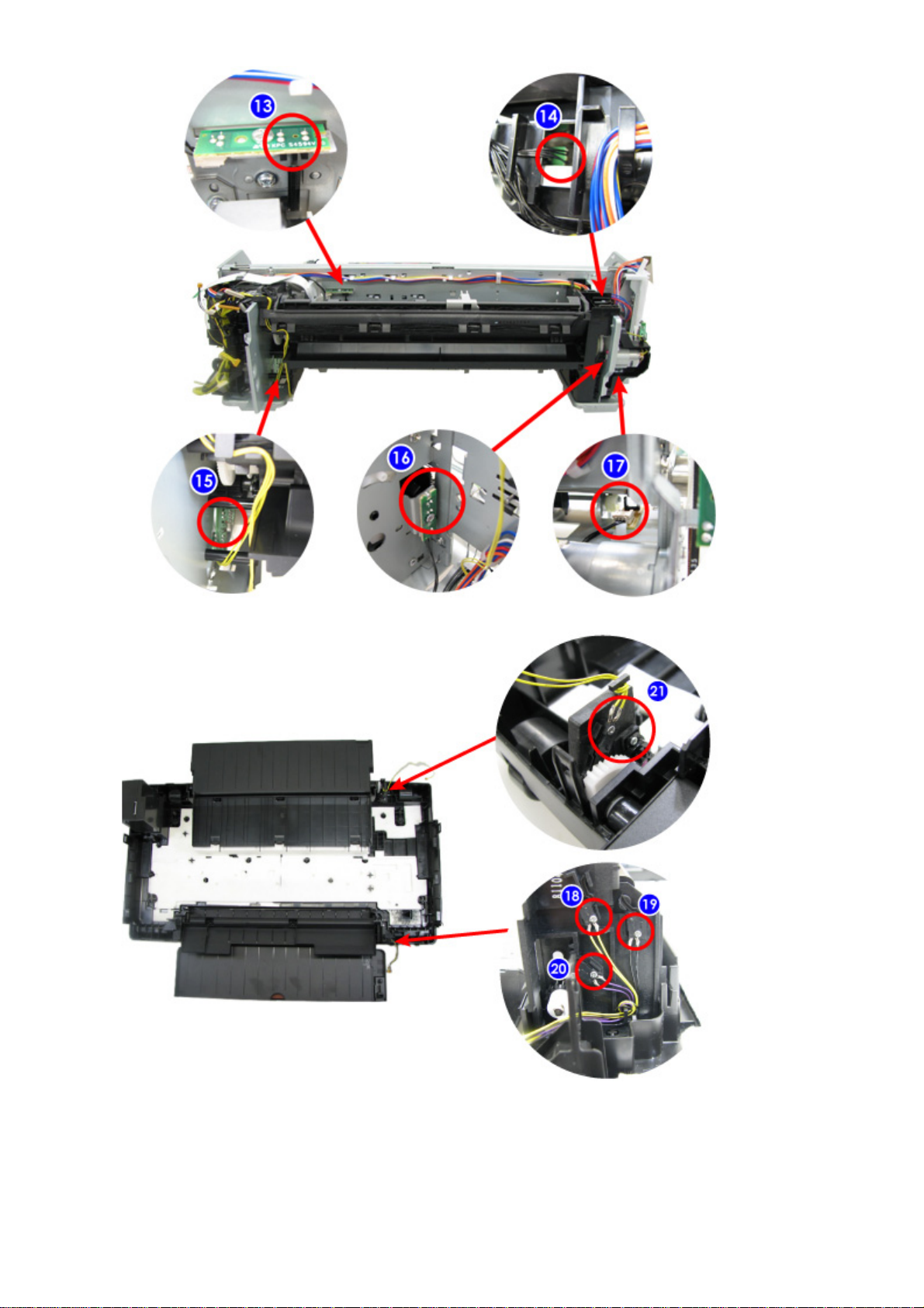
- Red screws as well as regular (silver) screws need adjustments during servicing.
- The screws securing the paper feed motor may be loosened only at replacement of the
paper feed motor unit. DO NOT loosen them in other cases.
- The screws securing the carriage shaft may be loosened only at removal of the carriage
unit. DO NOT loosen them in other cases.
- The screws securing the eject roller may be loosened only at removal of the platen
unit. DO NOT loosen them in other cases.
2 / 56
1-2. Customer Maintenance
*1: Only for CD / DVD printing supported regions.
Adjustment Timing Purpose Tool Approx.
time
Automatic print
head alignment - At print head replacement
- When print quality is not
satisfying (uneven printing,
etc.)
To ensure accurate
dot placement. - Printer buttons
- Computer
(printer
driver)
5 min.
Manual print head
alignment - At print head replacement
- When print quality is not
satisfying (uneven printing,
etc.)
To ensure accurate
dot placement. - Computer
(printer
driver)
10 min.
Print head
cleaning When print quality is not
satisfying. To improve nozzle
conditions. - Printer buttons
- Computer
(printer
driver)
1 min.
Print head deep
cleaning When print quality is not
satisfying, and not improved by
print head cleaning.
To improve nozzle
conditions. - Computer
(printer
driver)
2 min.
Ink tank
replacement When an ink tank becomes
empty. ("No ink error" displayed
on the PC monitor, or short
flashing of an ink tank LED)
To replace the
empty ink tank. --- 1 min.
Paper feed roller
cleaning - When paper does not feed
properly.
- When the front side of the
paper is smeared.
To clean the paper
feed rollers of the
rear tray.
- Computer
(printer
driver)
2 min.
Bottom plate
cleaning When the back side of the paper
is smeared. To clean the platen
ribs. (Feed the paper
from the rear tray.)
- Printer buttons
- Computer
(printer
driver)
1 min.
Exterior cleaning When necessary. To clean the printer
exterior, or to wipe
off dusts.
Soft, dry, and
clean lint-free
cloth.
1 min.
CD / DVD print
position
adjustment*1
At CD / DVD printing, when
necessary. To correct CD /
DVD print position. - Computer
(application
software)
5 min.
3 / 56
1-3. Special Tools
1-4. Sensors
Name Tool No. Application Remarks
FLOIL KG-107A QY9-0057-000 To the printer's sliding portions. In common with the Pro9000
and Pro9500.
EU-1 QY9-0037-000 To the carriage shaft sliding
portions. In common with the Pro9000
and Pro9500.
MOLYKOTE
PG641 CK-0562-000 To the printer's sliding portions. In common with the Pro9000
and Pro9500.
MOLYKOTE
HP300 QY9-0035-000 To the printer's sliding portions. In common with the Pro9000
and Pro9500.
FLOIL GP-1000R QY9-0071-000 To the PR lift shaft sliding
portions. In common with the Pro9000
and Pro9500.
No. Sensor Function Possible problems
1 Ink sensor Detects the position of an ink tank. - No recognition of an ink tank
- Wrong position of an ink tank
2Temperature
sensor Detects the temperature of the inside of the
printer. - Internal temperature error
3Carriage
encoder
sensor
Detects the position of the timing slit film,
and controls printing. - Printing shifts from the correct
position.
- Carriage position error
4Top cover
open sensor Detects opening and closing of the top
cover. - The carriage does not move to the
center.
5LF encoder
sensor Detects rotation of the LF encoder, and
controls its drive. - Uneven printing
- LF position error
6Eject encoder
sensor Detects rotation of the eject encoder, and
controls its drive. - Uneven printing at the trailing edge
of paper
- Eject encoder error
7Carriage lift
sensor Detects the position of the carriage lift cam. - Carriage lift mechanism error
8Remaining
ink amount
sensor
Detects presence of ink in the vessel of an
ink tank. - Wrong detection of the remaining
ink amount
9 Front feeding
PE sensor Detects paper feeding and ejection from the
front tray. - No paper
- Paper jam
10 Pump roller
sensor Detects the position of the pump roller - PG cam sensor error
11 Spur base lift Detects the position of the spur base lift - Spur base lift mechanism error
4 / 56
sensor cam.
12 Purge cam
sensor Controls purging operation. - PG cam sensor error
13 PE sensor Detects paper feeding and ejection. - No paper
- Paper jam
14 PRSB sensor Controls drive of the pressure roller lift cam
and spur base lift cam. - PRSB position error
15 AP sensor Controls paper feeding and purging
operation. - AP position error
16 PR cam
sensor Detects the position of the pressure roller lift
cam. - Paper cannot be set for front
feeding. (The pressure roller is in
the lowered position, preventing
paper from being inserted for front
feeding.)
17 LF position
sensor Detects the standard rotation position of the
feed roller. - LF error
18 Front tray
open sensor Detects opening and closing of the front
tray. - Front tray closed
19 Inner cover
open sensor Detects opening and closing of the inner
cover. - Errors relating to opening or
closing of the inner cover
20 Front tray
position
sensor
Detects whether the front tray is in the raised
position or lowered position. - Errors relating to the front tray
position (raised or lowered)
21 Front feed
support open
sensor
Detects opening and closing of the front feed
support (rear cover). - Front feed support closed
5 / 56
Click on the image to enlarge it.
6 / 56
7 / 56
1-5. Serial Number Location
On the carriage flexible cable holder (visible on the right of the carriage after the printer is turned on, the top
cover is opened, and the carriage moves to the center).
<1. MAINTENANCE>
8 / 56
2. LIST OF ERROR DISPLAY / TROUBLESHOOTING
Errors and warnings are displayed by the following ways:
1. Operator call errors are indicated by the Alarm LED lit in orange, and the error messages are
displayed by the printer driver Status Monitor.
2. Error codes (the latest 10 error codes at the maximum) are printed in the "operator call/service call
error record" area in EEPROM information print
Buttons valid when an operator call error occurs:
1. Power button: To turn the printer off and on again.
2. Resume/Cancel button: To cancel the job at error occurrence, and to clear the error.
2-1. Operator Call Errors (by Alarm LED Lit in Orange)
Pro9000 Mark II TABLE OF CONTENTS
Alarm
LED
blinking
in
orange
Error
Error
code U
No. Solution Parts that are likely to
be faulty
Alarm
LED lit Printing from the
front tray not
completed.
[1320] --- Set the paper, and press the
Resume/Cancel button. - Platen unit
- Front door unit
- Rear tray holder R unit
2 times No paper in the
rear tray. [1000] --- Confirm that the rear tray is
selected as the paper source.
Set the paper in the rear tray,
and press the Resume/Cancel
button.
- ASF unit
- Pressure roller unit
- PE sensor
- Paper feed motor
No CD-R tray.*1 [1001] --- Set the CD-R tray and press the
Resume/Cancel button. - CD-R tray
- Carriage unit
No CD or
DVD.*1 [1002] --- Set a CD or DVD in the CD-R
tray and insert the CD-R tray in
the proper position. Then, press
the Resume/Cancel button.
- CD-R tray
- Carriage unit
3 times Paper jam. [1300] --- Remove the jammed paper or
foreign material causing a
paper jam (paper remainings,
clips, pens, etc.), and press the
Resume/Cancel button.
- ASF unit
- Pressure roller unit
- PE sensor
- Feed roller
- Platen unit
Front tray closed [1250] --- Open the front tray. (The error
is indicated when the front tray
is not opened at start of
printing, or when the front tray
is closed during printing.)
- Front door unit
- Front cover R unit
Front feed
support closed [1260] --- Open the front feed support.
(The error is indicated when - Rear tray unit
- Rear tray holder R unit
9 / 56
the front feed support is closed
at paper feeding from the front
tray.)
4 times Ink may have
run out. [1600] U041 Replace the applicable ink
tank, or press the
Resume/Cancel button to clear
the error without ink tank
replacement. When the error is
cleared by pressing the
Resume/Cancel button, ink
may run out during printing.
- Ink tank
- Remaining ink detection sensor
- Logic board
Ink tank not
installed. [1660] U043 Install the applicable ink tank
(s) properly, and confirm that
the LED's of all the ink tanks
light red.
- Ink tank
- Carriage unit
- Logic board
5 times Print head not
installed, or not
properly
installed.
[1401] U051 Install the print head properly. - Print head
- Carriage unit
- Logic board
Faulty print head
ID. U052 Re-set the print head. If the
error is not cleared, the print
head may be defective. Replace
the print head.
- Print head
- Logic board
Print head
temperature
sensor error.
[1403]
Faulty EEPROM
data of the print
head.
[1405]
6 times Inner cover
open*2 [1841] --- Close the inner cover and press
the Resume/Cancel button. - Front door unit
- Inner cover unit
- Front cover R unit
Inner cover open
during printing
on paper*2
[1846] ---
Inner cover open
during printing
on paper (print
continuable)*1
[1851] ---
Inner cover open
during printing
on paper (print
NOT
continuable)*1
[1856] --- Close the inner cover and press
the Resume/Cancel button to
clear the error. The paper being
printed at error occurrence will
be ejected without printing the
remaining data for the ejected
paper, then printing will
resume from the next page.
Inner cover
closed during [1850] --- Open the inner cover, set the
CD-R tray on it, and press the
10 / 56
CD / DVD
printing (print
continuable)*1
Resume/Cancel button.
Inner cover
closed during
CD / DVD
printing (print
NOT
continuable)*1
[1855] --- Open the inner cover and press
the Resume/Cancel button to
clear the error. The CD or
DVD being printed at error
occurrence will be ejected
without printing the remaining
data for the ejected CD or
DVD, then the next print job
will be performed.
7 times Multiple ink
tanks of the
same color
installed.
[1487] U071 Replace the wrong ink tank(s)
with the correct one(s). - Ink tank
- Logic board
Ink tank in a
wrong position. [1680] U072 Install the ink tank(s) in the
correct position.
8 times Warning: The
ink absorber
becomes almost
full.
[1700] --- Replace the ink absorber, and
reset its counter. [See 4-4.
Special Notes on Servicing, (5)
Ink absorber counter setting.]
Pressing the Resume/Cancel
button will exit the error, and
enable printing without
replacing the ink absorber.
However, when the ink
absorber becomes full, no
further printing can be
performed unless the
applicable ink absorber is
replaced.
- Absorber kit
9 times The connected
digital camera or
digital video
camera does not
support Camera
Direct Printing.
[2001] --- Remove the cable between the
camera and the printer. - DSC harness
- Logic board
10 times Front tray in the
raised position
(print
continuable)
[1281] --- Lower the front tray, and press
the Resume/Cancel button.
(The error is indicated when
the front tray is in the raised
position at the start of printing
from the rear tray.)
- Front door unit
- Front cover R unit
Front tray in the
lowered position
(print
[1282] --- Raise the front tray, and press
the Resume/Cancel button.
(The error is indicated when
11 / 56
continuable) the front tray is in the lowered
position at the start of printing
from the front tray.)
Front tray in the
raised position
(print NOT
continuable)
[1283] --- Lower the front tray, and press
the Resume/Cancel button.
(The error is indicated when
the front tray is raised position
during printing from the rear
tray.)
Front tray in the
lowered position
(print NOT
continuable)
[1284] --- Raise the front tray, and press
the Resume/Cancel button.
(The error is indicated when
the front tray is lowered during
printing from the front tray.)
11 times Failed in
automatic print
head alignment
[2500] --- Press the Resume/Cancel
button to clear the error, then
perform the automatic print
head alignment again.
- Print head
- Ink tank
- Carriage unit
- Logic board
Paper size
smaller than
specified
[1062] --- Press the Resume/Cancel
button. (The paper will be
ejected, and the print job will
be cancelled automatically.)
The error is indicated when the
size of paper actually set is
smaller than the one selected in
the printer driver, to prevent
printing on the platen.
(e.g. When A4 paper is set in
the printer though A3 is
selected in the printer driver,
the error occurs. If A3 paper is
set in the printer and A4 is
selected in the printer driver,
then the error does not occur.)
- Carriage unit
- Logic board
12 times Paper not set
properly in the
front tray, or
non-supported
size of paper set
in the front tray
[1321] --- Press the Resume/Cancel
button to clear the error, then
set a supported size of paper
properly in the front tray.
- Platen unit
- Feed roller
- Paper feed motor
13 times The remaining
ink amount
unknown (raw
ink present).
[1683] U130 An ink tank which has once
been empty is installed.
Replace the applicable ink tank
with a new one. Printing with a
once-empty ink tank can
damage the printer.
To continue printing without
- Ink tank
- Logic board
- Carriage unit
12 / 56
*1: Only for CD / DVD printing supported regions.
*2: Only for CD / DVD printing no-supported regions.
replacing the ink tank(s), press
the Resume/Cancel button for 5
sec. or longer to disable the
function to detect the
remaining ink amount. After
the operation, it is recorded in
the printer EEPROM that the
function to detect the
remaining ink amount was
disabled.
14 times Ink tank not
recognized. [1684] U140 A non-supported ink tank (an
ink tank that is sold in a
different region from where the
printer was purchased) is
installed (the ink tank LED is
turned off). Install the
supported ink tanks.
- Ink tank
- Logic board
- Carriage unit
15 times Ink tank not
recognized. [1682] U150 A hardware error occurred in
an ink tank (the ink tank LED
is turned off). Replace the ink
tank(s).
- Ink tank
- Logic board
- Carriage unit
16 times No ink (no raw
ink). [1688] U163 Replace the empty ink tank(s),.
Printing with an empty ink tank
can damage the printer.
To continue printing without
replacing the ink tank(s), press
the Resume/Cancel button for 5
sec. or longer to disable the
function to detect the
remaining ink amount. After
the operation, it is recorded in
the printer that the function to
detect the remaining ink
amount was disabled.
- Ink tank
- Logic board
- Carriage unit
19 times Non-supported
hub. [2002] --- Remove the applicable USB
hub from the PictBridge (USB)
connector.
- DSC harness
- Logic board
13 / 56
2-2. Service Call Errors (by Cyclic Blinking of Alarm and Power LEDs)
Service call errors are indicated by the number of cycles the Alarm and Power LEDs blink, and the
corresponding error code with the message, "A printer error has occurred. Turn the printer off and then
on again. If this doesn't clear the error, see the user's guide for more detail." is displayed in the printer
driver Status Monitor.
Cycles of
blinking
of Alarm
and
Power
LEDs
Error Error
code Conditions Solution
(Check points and replacement
items)
2 times Carriage
error [5100] An error occurred in the
carriage encoder signal. (1) Smearing or scratches on the carriage
slit film;
clean the timing slit film.
(2) Foreign material or paper debris that
obstructs the carriage movement;
remove foreign material.
(3) Ink tank conditions;
re-set the ink tanks.
(4) Cable connection
(5) Part replacement:
- Timing slit film
- Carriage unit
- Logic board
- Carriage motor
3 times Line feed
error [6000] An error occurred in the
LF encoder signal. (1) Smearing or scratches on the LF slit
disk film;
clean the LF slit disk film.
(2) Foreign material or paper debris in the
LF drive;
remove foreign material.
(3) Cable connection
(4) Part replacement:
- LF slit disk film
- LF / EJ timing sensor unit
- Paper feed roller unit
- Logic board
- Paper feed motor
4 times Purge cam
sensor error [5C00] An error occurred in the
purge unit. (1) Foreign material or paper debris around
the purge unit;
remove foreign material.
(2) Cable connection
(3) Part replacement:
- Purge unit
- Logic board
5 times ASF (cam)
sensor error [5700] An error occurred in the
ASF cam sensor during (1) Cable connection
(2) Part replacement:
14 / 56
paper feeding from the
rear tray. - ASF unit
- Logic board
6 times Internal
temperature
error
[5400] The internal temperature is
not normal. (1) Cable connection
(2) Part replacement:
- Carriage unit
- Logic board
- Print head
7 times Ink absorber
full [5B00,
5B01] The ink absorber is
supposed to be full.
Error codes:
5B00: Overseas
5B01: Japan (In
EEPROM information
print, "5B00" is printed
instead of "5B01.")
(1) Ink absorber condition
(2) Part replacement:
- Ink absorber kit
(3) Ink absorber counter value in the
EEPROM;
reset the ink absorber counter.
8 times Print head
temperature
rise error
[5200] The print head temperature
exceeded the specified
value.
(1) Print head condition
(2) Cable connection
(3) Part replacement:
- Print head
- Logic board
9 times EEPROM
error [6800,
6801] A problem occurred in
reading from or writing to
the EEPROM.
(1) Part replacement:
- Logic board
10 times VH monitor
error [B200] The VH (print head drive
voltage) is out of the
specified value.
(1) Part replacement:
- Print head and logic board
(Replace them at the same time.)
- Carriage unit
- Power supply unit
11 times Carriage lift
mechanism
error
[5110] The carriage did not move
up or down properly. (1) Foreign material or paper debris that
obstructs the carriage movement;
remove foreign material.
(2) Part replacement:
- Carriage lift gear unit
- Carriage lift sensor
- ASF unit
- Logic board
12 times AP position
error [6A00] An error occurred in the
AP motor (on the right
side of the ASF unit).
(1) Foreign material or paper debris around
the ASF unit;
remove foreign material.
(2) Cable connection
(3) Part replacement:
- ASF unit
- Logic board
13 times PRSB
position
error
[6B00] An error occurred in the
PRSB motor (on the left
side of the ASF unit).
17 times Paper eject
encoder
error
[6010] An error occurred in the
paper eject encoder signal. (1) Smearing or scratches on the EJ slit disk
film;clean the EJ slit disk film.
(2) Foreign material or paper debris in the
15 / 56
paper path;
remove foreign material.
(3) Cable connection
(4) Part replacement:
- EJ slit disk film
- LF / EJ timing sensor unit
- Platen unit
- Logic board
- Paper feed motor
18 times Spur base lift
mechanism
error
[5120] The spur base did not
move up or down
properly.
(1) Cable connection
(2) Part replacement:
- ASF unit
- Spur base lift unit
- Logic board
19 times Ink tank
position
sensor error
[6502] None of the ink tank
position is detected. (1) Ink tank position;
confirm the ink tank position.
(2) Re-set or replacement of ink tanks
(3) Cable connection
(4) Part replacement:
- Ink tank position sensor error
- Logic board
20 times Other errors [6500] An unidentified error or a
network error occurred. (1) Part replacement:
- Logic board
Before replacement of the logic board ass'y, check the ink absorber counter value (by
service test print or EEPROM information print). If the counter value is 7% or more,
also replace the ink absorber kit when replacing the logic board ass'y. If the counter
value is less than 7%, register the current ink absorber counter value to the replaced new
logic board instead. [See 4-4. Special Notes on Servicing, (5) Ink absorber counter
setting, for details.]
16 / 56
2-3. Troubleshooting by Symptom
Symptom Solution (Parts that are likely to be faulty)
Faulty
operation The power does not turn on.
The power turns off
immediately after power-on.
(1) Confirm connection of the power supply unit:
- Harness and connector conditions
(2) Replace the following item(s):
- Logic board
- Power supply unit
- Front cover R unit
A strange noise occurs. (1) Examine and remove any foreign material or paper
debris.
(2) Replace the following item(s):
- The part generating the strange noise
- Logic board
Paper feed problems (multi-
feeding, skewed feeding, no
feeding).
(1) Examine and remove any foreign material or paper
debris.
(2) Confirm cable connection.
(3) Replace the following item(s):
- ASF unit
- PE sensor board
- Pressure roller unit
- Platen unit
Unsatisfactory
print quality No printing, or no color ejected.
Faint printing, or white lines on
printouts.
Uneven printing.
Improper color hue.
(1) Confirm the ink tank conditions:
- Confirmation of the air-through of an ink tank
- Re-setting of an ink tank
(2) Remove foreign material from the purge unit caps, if
any.
(3) Perform cleaning or deep cleaning of the print head.
(4) Perform print head alignment.
(5) Replace the following item(s):
- Print head*1, and ink tanks
- Logic board
- Purge unit
Paper gets smeared. (1) Clean the inside of the printer.
(2) Perform bottom plate cleaning.
(3) Perform paper feed roller cleaning.
The back side of paper gets
smeared. (1) Clean the inside of the printer.
(2) Perform bottom plate cleaning.
(3) Examine the platen ink absorber.
(4) Examine the paper eject roller.
(5) Replace the following item(s):
- The part in the paper path causing the smearing
Graphic or text is enlarged on
printouts in the carriage
movement direction.
(1) Confirm that the timing slit film is free from smearing
or scratches:
- Cleaning of the timing slit film.
(2) Replace the following item(s):
17 / 56

Other manuals for PIXMA Pro9000 Mark II Series

6

Other Canon Printer manuals

Canon PIXMA iP2000 Series Instructions for use

Canon

Canon PIXMA iP2000 Series Instructions for use

Canon Pixma iP4850 User manual

Canon

Canon Pixma iP4850 User manual

Canon imagePROGRAF TA-30 User manual

Canon

Canon imagePROGRAF TA-30 User manual

Canon LBP7018C Guide

Canon

Canon LBP7018C Guide

Canon iPF610 - imagePROGRAF Color Inkjet Printer User manual

Canon

Canon iPF610 - imagePROGRAF Color Inkjet Printer User manual

Canon i560 Series User manual

Canon

Canon i560 Series User manual

Canon MB2720 User manual

Canon

Canon MB2720 User manual

Canon imagePROGRAF TA-30 Setup guide

Canon

Canon imagePROGRAF TA-30 Setup guide

Canon iPF750 - imagePROGRAF Color Inkjet Printer User manual

Canon

Canon iPF750 - imagePROGRAF Color Inkjet Printer User manual

Canon LASER SHOT LBP6000 User manual

Canon

Canon LASER SHOT LBP6000 User manual

Canon LBP 3370 User manual

Canon

Canon LBP 3370 User manual

Canon Pixma MG3500 Series User manual

Canon

Canon Pixma MG3500 Series User manual

Canon PIXMA MG7150 Setup guide

Canon

Canon PIXMA MG7150 Setup guide

Canon iP1900 Series User guide

Canon

Canon iP1900 Series User guide

Canon BJC 210 - Color Inkjet Printer User manual

Canon

Canon BJC 210 - Color Inkjet Printer User manual

Canon g3000 series User manual

Canon

Canon g3000 series User manual

Canon LBP631Cw User manual

Canon

Canon LBP631Cw User manual

Canon IMAGERUNNER ADVANCE SERIES Installation guide

Canon

Canon IMAGERUNNER ADVANCE SERIES Installation guide

Canon K10158 User manual

Canon

Canon K10158 User manual

Canon MAXIFY MB2320 Instruction Manual

Canon

Canon MAXIFY MB2320 Instruction Manual

Canon PIXMA MX420 Series User instructions

Canon

Canon PIXMA MX420 Series User instructions

Canon NP-1215 User manual

Canon

Canon NP-1215 User manual

Canon iR C6800 Series Operating and maintenance manual

Canon

Canon iR C6800 Series Operating and maintenance manual

Canon TS9500 Series Setup guide

Canon

Canon TS9500 Series Setup guide

Popular Printer manuals by other brands

Epson ActionLaser Plus user manual

Epson

Epson ActionLaser Plus user manual

Epson SC-F7100 series user guide

Epson

Epson SC-F7100 series user guide

Epson ET-4810 Series Start here

Epson

Epson ET-4810 Series Start here

Epson R800 - Stylus Photo Color Inkjet Printer user guide

Epson

Epson R800 - Stylus Photo Color Inkjet Printer user guide

Roland SOLJET PROIII XC-540 Setup guide

Roland

Roland SOLJET PROIII XC-540 Setup guide

IBM InfoPrint 20 Quick reference card

IBM

IBM InfoPrint 20 Quick reference card

Dascom DP-540 Quick setup guide

Dascom

Dascom DP-540 Quick setup guide

Fujitsu FTP-621CDL003 Specification sheet

Fujitsu

Fujitsu FTP-621CDL003 Specification sheet

Epson SpectroProofer Mounter 17" user guide

Epson

Epson SpectroProofer Mounter 17" user guide

Star Micronics TSP200 Series Programmer's manual

Star Micronics

Star Micronics TSP200 Series Programmer's manual

VinTelecom FS10 user manual

VinTelecom

VinTelecom FS10 user manual

AMT Datasouth Documax 5380 quick start guide

AMT Datasouth

AMT Datasouth Documax 5380 quick start guide

Panasonic SP28P Operating instructions and installation manual

Panasonic

Panasonic SP28P Operating instructions and installation manual

Panasonic KX-P3626 operating instructions

Panasonic

Panasonic KX-P3626 operating instructions

Magtek ExpressCard 500 user guide

Magtek

Magtek ExpressCard 500 user guide

Tektronix Phaser 560 Service manual

Tektronix

Tektronix Phaser 560 Service manual

Avery Dennison Monarch 9825 quick reference

Avery Dennison

Avery Dennison Monarch 9825 quick reference

Wincor Nixdorf TH180 user manual

Wincor Nixdorf

Wincor Nixdorf TH180 user manual

manuals.online logo
manuals.online logoBrands
  • About & Mission
  • Contact us
  • Privacy Policy
  • Terms and Conditions

Copyright 2025 Manuals.Online. All Rights Reserved.