Canvas LFT1224PST-A User manual

Production Number: XXXXXXXX
GRANVILLE OUTDOOR
FIRE TABLE
MODEL N0. 085-1562
LFT1224PST-A
ASSEMBLY INSTRUCTIONS
Toll-free 1-888-670-6684
IMPORTANT: Please read this manual carefully before beginning assembly of this product.
Keep this manual for future reference.

WARNING: For Outdoor Use Only.
DANGER
If you smell gas:
1. Shut off gas to the appliance.
2. Extinguish any open flame.
3. If odour continues, keep away from the
appliance and immediately call your gas
supplier or fire department.
Propane tank not included
AA battery needed, not included
Please dispose of or recycle the batteries
according to municipal requirements.
WARNING:
Improper installation, adjustment, alteration,
service or maintenance can cause injury or
property damage. Read the installation,
operating and maintenance instructions
thoroughly before installing or servicing
this equipment.
WARNING:
Do not store or use gasoline or other flammable liquids and vapours in the vicinity of this or any
other appliance.
An LP-cylinder not connected for use must not be stored in the vicinity of this or any other
appliance.
DANGER CARBON MONOXIDE HAZARD
This appliance can produce carbon monoxide which has no odour.
Using it in an enclosed space can kill you.
Never use this appliance in an enclosed space such as a camper, tent,
car or home.
This appliance complies with ANSI Z21.97-2014/CSA 2.41-2014, Outdoor Decorative Gas Appliances.
GRANVILLE OUTDOOR FIRE TABLE

3MODEL N0. 085-1562
LFT1224PST-A
TABLE OF CONTENTS
GENERAL INFORMATION
General Information
Specifications
Important Safety Information and Precautions
Expanded View
Parts List
Installation
Location
Setup
Gas Connection
Operation
Leak Test
Lighting the Burners
Storage and Maintenance
Trouble Shooting
Limited Warranty
3
4
4-5
6
7
9
9
10
9
10
11
8
7
8
8
IMPORTANT
please take time to read these instructions thoroughly and follow each step carefully for safe and easy
operation. Retain for future reference, and read carefully.

4
Product name
Model No.
Rated Heat Output
Fuel
Gas Supply
Manifold Pressure
Orifice Size (diameter)
Gas Supply Pressure
GRANVILLE OUTDOOR FIRE TABLE
SPECIFICATIONS
IMPORTANT SAFETY INFORMATION AND PRECAUTIONS
085-1562/LFT1224PST-A
26,000 BTU/HR
Propane-LP
20 lb. LP-gas cylinder
11 Inches W.C.
1.57 mm
Max. 250 PSI
When the appliance is connected to a fixed piping system, the installation must comply with
local codes, or in the absence of local codes with the National Fuel Gas Code, ANSI Z223.1/NF-
PA54; the International Fuel Gas codes, Natural Gas and Propane Installation Code, CSA B149.1;
or the Propane Storage and Handling Code, B149.2, as applicable.
The LP gas supply cylinder to be used must be:
1- Constructed and marked in accordance with the U.S. Department of Transportation (D.O.T.)
Specifications for LP-Gas Cylinders, or the Standard for Cylinders, Spheres and Tubes for Transportation
of Dangerous Goods and Commission, CAN/CSA-B339, as applicable;
2- Provided with a listed overfilling prevention device;
3- Provided with a cylinder connection device compatible with the connection for the appliance.
Always place the appliance on a firm and level surface.
Solid fuels must not be burned in this gas appliance. When using decorative
Tempered glass, use
only Tempered glass (INCLUDED).
The appliance must only be used outdoors in a well-ventilated space and must not be used in a
building, garage or any other enclosed area.
When in use, keep the appliance area clear and at least 40 in / 101.6 cm side clearance from com-
bustible materials, gasoline and other flammable liquid and vapours. Do not use the appliance
under overhead combustible surfaces. Certain items or materials, when stored under the appli-
ance or nearby, will be subjected to radiant heat and could be damaged.
When in use, keep cylinder area clear and at least 30 in / 76.2 cm side clearance from combusti-
ble materials, gasoline and other flammable liquid and vapours. Do not use the appliance under
overhead combustible surfaces. Certain items or materials, when stored under the appliance or
nearby, will be subject to radiant heat and could be damaged.

5MODEL N0. 085-1562
LFT1224PST-A
IMPORTANT SAFETY INFORMATION AND PRECAUTION
I
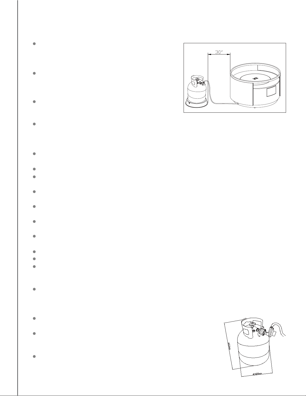
The minimum distance between the brazier and the
cylinder is 30 in / 76.2 cm, which prevents the hosepipe
from falling between the cylinder and the brazier.
WARNING: The cylinder poses a risk of tripping.
nspect the hose assembly and burner prior to each use.
If there is evidence of excessive abrasion or wear, or if
the hose or burner is damaged, it must be replaced by
an appropriate part from the manufacturer.
Open the door and inspect the gas connections prior to
each use. Do not operate the unit if there is a gas leak.
Have the appliance inspected annually by a qualified service person.
The pressure regulator and hose assembly provided with the appliance must be used. The replace-
ment part must be the same as the part specified by the manufacturer.
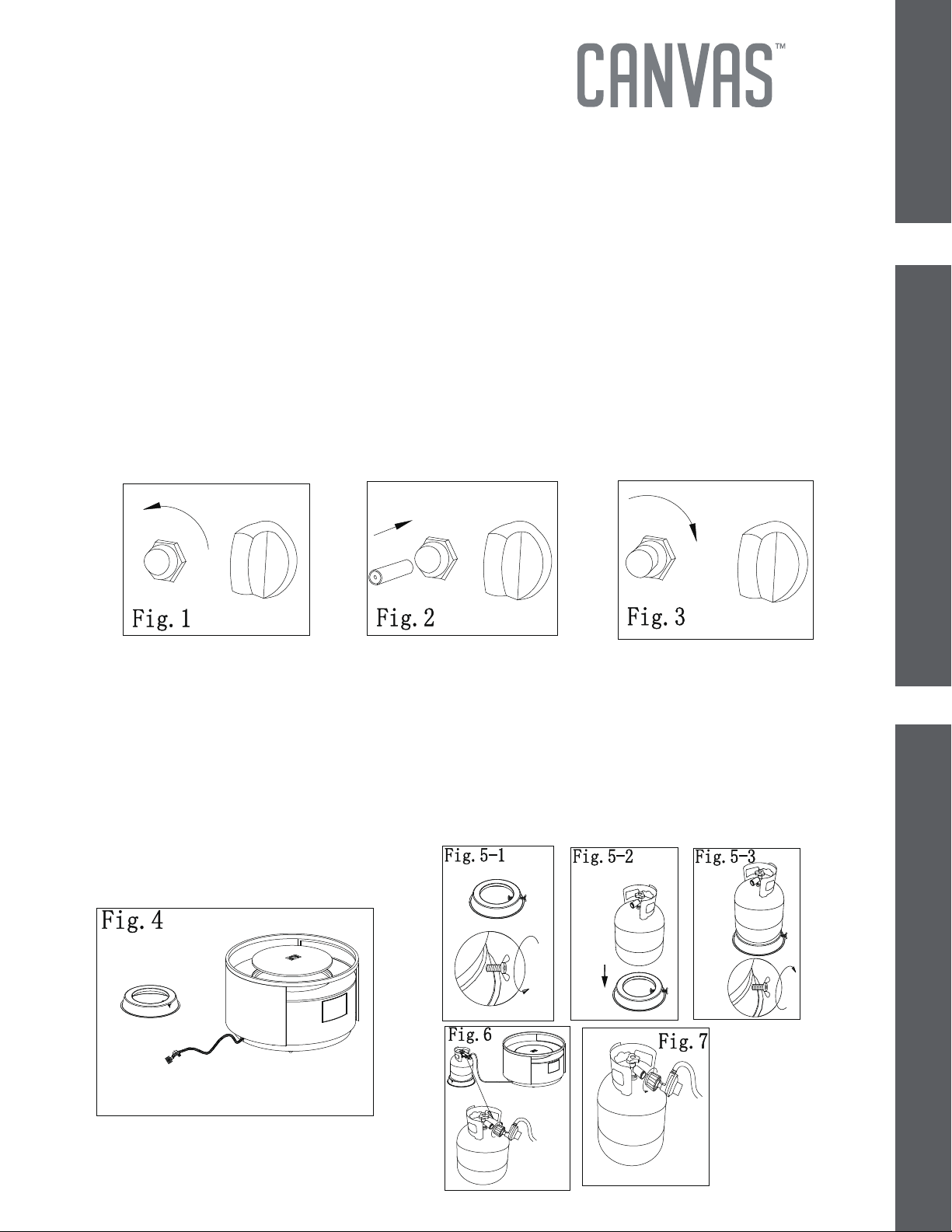
For the assembly of LP-gas and leak checking, please refer to “Gas Connection” on page 8 and
“Leak Test” on page 9.
Children and adults should be alerted to the hazards of high surface temperatures and should stay
away to avoid burns and prevent clothing ignition.
Young children and pets should be carefully supervised when they are in the area of the appliance.
Any guard or other protective device removed for servicing the appliance must be replaced prior
to operation.
Clothing or other flammable materials should not be hung from the appliance or placed on or near
the appliance.
Do not use this appliance if any part has been under water. Immediately call a service technician to
inspect the appliance and to replace any part of the control system which has been under water.
The LP-gas supply cylinder to be used must be constructed and marked in accordance with the specifi-
cations for LP-gas cylinders of the U.S. Department of Transportation (D.O.T.).
The cylinder supply system must be arranged for vapour withdrawal and the cylinder must include
a collar to protect the cylinder valve.
Use only 20 lb / 9 kg LP-gas cylinders.
Do not burn wood or any other materials in this appliance.
The appliance must be isolated from the gas supply piping system by closing its individual manual
shutoff valve during any pressure testing of the gas supply piping system at test pressure equal to or
less than 1/2 PSI (3.5 kPa).
Other cylinders may be acceptable for use with the appliance, provided they are compatible with
the appliance retention means and accompanied by illustration(s) depicting the cylinder mounted on
the appliance using the cylinder retention means and the point of contact between the cylinder and
the retention means.
Properly place the hose out of pathways where people may trip over it or
in areas where they may be subject to accidental damage.
The burner must be replaced prior to the appliance being put into
operation if it is clear that the burner is damaged. The replacement burner
must be the same as the part specified by the manufacturer.
To clean the appliance including the burner, please refer to “Storage and
Maintenance” on page 10.

6
EXPANDED VIEW

7MODEL N0. 085-1562
LFT1224PST-A
INSTALLATION
PARTS LIST
Installation will be much easier with two or more people.
If you want to replace the parts listed, please contact the Customer Service Centre 1(888) 670-6684.
The cover C as shown on the cover. Cylinders are placed on the edge.
(Note that the minimum distance is 30 in).
No. Description
Qty
A
B
C
D
E
1
1
1
1
Outer ring(pre-assembled)
P22404A01144
Main body(pre-assembled )
P21125A01145
Lid
P20709A01145
Cylinder ring
P20803A01144
Tempered glass
P99960A02003
Step 1
1 (5
kg
)

1- Clean the valve and place the cylinderon the main body. See Fig 4.
2- Release the cylinder of the cylinder ring as shown in the figure. See Fig 5-1; then place
the cylinder on the cylinder. See Fig 5-2; then tighten the cylinder of the cylinder, See
Fig 5-3.
3- Connect the regulator and the cylinder as shown in Fig 6. Make sure there is no leakage
or damage (please refer to “Leak Test” on page 9 and how to check for damage as
described on page 4).
4- Disconnect the regulator and the
cylinder as shown in Fig 7.
LOCATION
SETUPGAS CONNECTION
Your gas appliance must be installed on a flat, stable surface, away from any combustible
materials or construction.
Your gas appliance comes assembled, ready for a gas connection.
1- Remove the appliance from the box and place it on any level, outdoor,
non-combustible surface.
NOTE: Do not place this appliance on grass or dirt. These surfaces may prevent proper
safety venting.
2- Open the gas door and put the cylinder inside.
3- Unscrew the battery box as shown in Fig 1. Insert the negative electrode side of
the battery into the bottom of battery box as shown in Fig 2. Then screw the battery
box as shown in Fig 3.
Note: If the battery of the pulse electronic igniter runs out of power, please replace the
new battery as shown above.
8

Do not use an open flame to check for leaks.
Do not smoke during testing.
Do not test indoors.
A leak test must be performed whenever the gas cylinder is replaced.
!!!WARNING!!!
NOTE:
While in use, the burner flame should be mainly blue in appearance with a small
amount of yellow. The flame can be identified by the following figure.
1. Make sure the control knob is in the “OFF” position.
2. Make sure the gas cylinder is correctly and securely connected to the pressure regulator,
without over-tightening.
3. Turn on the gas cylinder valve. Apply a 50% soap and 50% water solution to the gas hose
and connections between the control knob and gas cylinder.
4. If something is leaking, you will see bubbles form. In case of leaks, turn off the gas supply,
undo the leaking connection, re-connect it and try again. If the leak persists, consult Customer
Service Centre for assistance (1-888-670-6684).
5. If the connection does not leak, continue to the next step.
1. Make sure the control valve is OFF.
2. Turn on the gas tank valve.
3. Press and turn the control valve knob counterclockwise to LOW
to light. See the figure to the right.
4. If the burner is lit, continue pressing in the control valve knob
for one minute to heat the thermocouple.
5. When the turn the control valve knob is released, the burner should
be lit. If not, turn the control valve knob clockwise to OFF. Wait
5 minutes then start with step 3 above.
6. Press and the control valve knob to desired heat output,
LOW ~ HIGH.
LEAK TEST
9MODEL N0. 085-1562
LFT1224PST-A
LIGHTING THE BURNERS
OPERATION AND LEAK TEST
OFF
HIGH
MAX
BAS
ARRET
LOW
Warning: Lighting the fire table improperly could lead to unsafe conditions.
7. Press and turn the control valve knob clockwise to OFF to shut down the fire pit.
Close the gas cylinder valve when the fire pit is not in use.
(CAUTION: Do not kink flexible gas hose. If it is kinked, a gas leak could occur.)

10
STORAGE AND MAINTENANCE
TROUBLE SHOOTING
To obtain the best performance from your fire table, you must perform the following
storage and maintenance activities on a regular basis:
Allow at least 35 minutes for the fire table to cool down after
use, before disconnecting and removing the gas cylinder.
Store the gas cylinder in a dry, well-ventilated and
sheltered area protected from inclement weather and dust,
out of the reach of children, and not in a building, garage or
any other closed area.
The fire table may be stored indoors only if the cylinder is
disconnected and removed.
Keep the fireplace area clear and free from combustible materials,
gasoline and other flammable vapours and liquids.
Installation and repair should be done by a qualified service person. The fire table
should be inspected before use and at least annually by a qualified service person.
More frequent cleaning may be required as necessary. It is imperative that the control
compartment, burner, and circulating air passageways of the fire table be kept clean.
If you disassemble the burner when cleaning the fire table, please reassemble it
according to the above-right picture to make sure the burner induction tunnel is on
and precisely covers the orifice base. It is imperative that the control compartment,
burner, and circulating air passageways of the fire table be kept clean. It is recommended
not to disassemble the burner.
Permanent installation and repair should be done by a qualified service person. The
fire table should be inspected annually by a qualified service person.
PROBLEM OBSERVED POSSIBLE CAUSE CORRECTIVE MEASURES
Gas odour Gas l
Low gas pressure
Clogged or dirty burner
ports
Blocked orifice
Spent battery
Incorrect gas supply or
pressure
Blocked orifice
Clogged or dirty burner ports
If you want to replace the parts listed, please contact Customer Service Centre (1-888-670-6684).
eak See “If you smell gas:” on front
cover of manual
Check all gas connections
erusserpylppussagkcehCnoitingideyaleD
Clean burner ports-see manual
section
Check orifice opening
Change new battery
erusserpylppussagkcehCemalfrenrubtcerrocnI
Check and clean orifice opening
Clean burner ports

11 MODEL N0. 085-1562
LFT1224PST-A
LIMITED WARRANTY
Made in China
Subject to the conditions set out below, this product is guaranteed against defects in materials
and workmanship for one (1) year from thedate of purchase!
Satisfactory proof of the purchase date must be provided at the time of notification of the
defect for any claim under the warranty to be enforceable.
This warranty covers all parts found defective in workmanship and/or materials during the
warranty period and can be repaired or replaced at the discretion of the manufacturer at no
cost to the original purchaser.
This warranty will be void if the product has not been assembled, installed or operated
according to the instructions, or subjected to abuse, improperly treated, neglected, rusted
by exposure to the elements, misused and/or if any repairs, maintenance, or service has
been done by an unauthorized person.
Returns must be properly packaged and returned to the dealer from whom the product
was acquired.
The manufacturer, distributor and retailer will not be liable for any incidental or conse-
quential loss or damage arising from the installation or operation of the product and/or the
failure of any part for any reason.
There are no other express or implied warranties, except for those stipulated herein. This
warranty gives specific rights and the original purchaser may have additional rights and
remedies in law.
This warranty does not cover commercial use.
Please do not return this product to the store. For technical assistance on assembly or
replacement parts call 1(888) 670-6684 from 8:00 AM EST to 8:00 PM PST.
This manual suits for next models
1
Table of contents
Other Canvas Outdoor Fireplace manuals

Canvas
Canvas 085-1548 User manual

Canvas
Canvas Dashley 085-1557-8 User manual

Canvas
Canvas 088-0733-8 User manual

Canvas
Canvas 085-1258-0 User manual

Canvas
Canvas 085-1584-2 User manual

Canvas
Canvas WESTMOUNT FHTS80048C User manual

Canvas
Canvas BIRMINGHAM 085-1280-4 User manual

Canvas
Canvas 085-1548-0 User manual

Canvas
Canvas 085-1558-6 User manual

Canvas
Canvas 088-0538-4 User manual