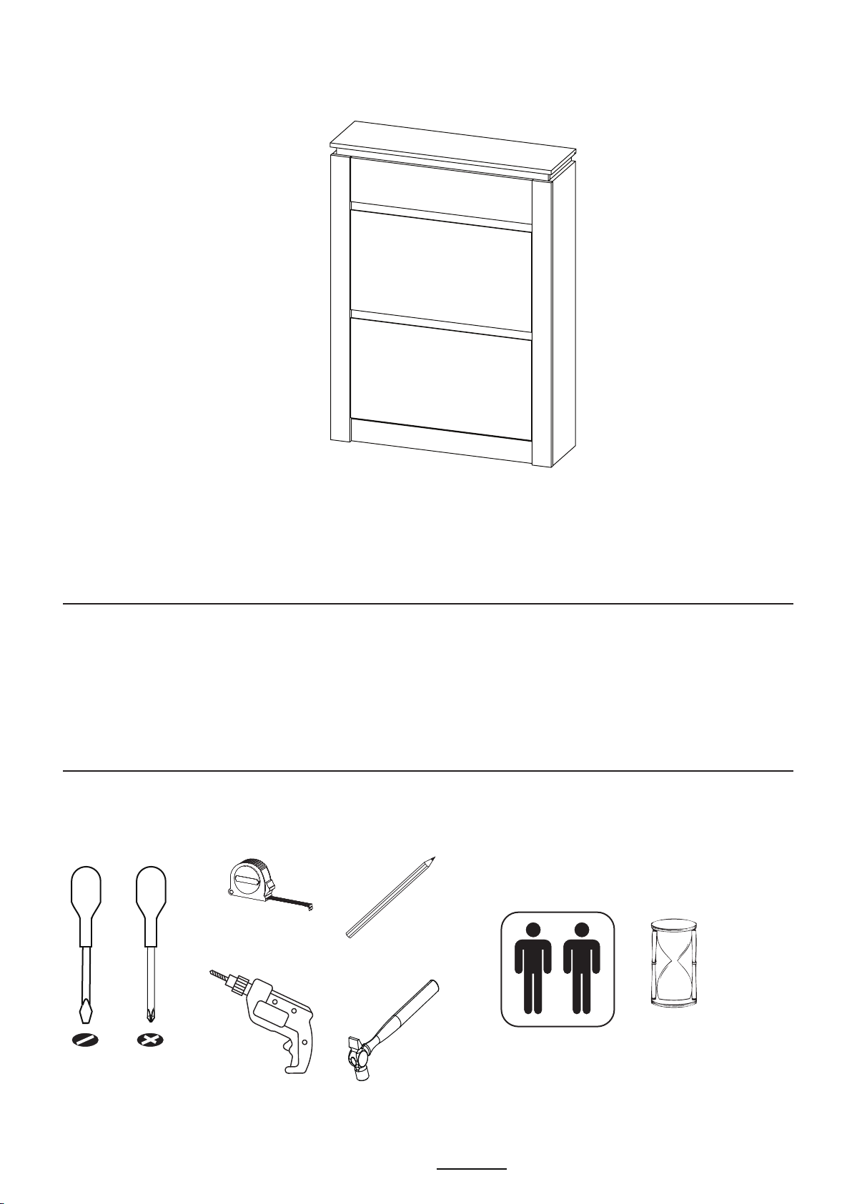
CANYON 2 TIER SHOE CABINET ASSEMBLY INSTRUCTIONS
Version 1 - 210821
Page 2of 18
IMPORTANT - READ CAREFULLY - RETAIN THESE INSTRUCTIONS FOR
FUTURE REFERENCE.
INFORMATION
CARE INFORMATION
To clean, wipe with a damp cloth.
Never use scourers, abrasives or chemical cleaners.
Do not use solvent based cleaners or detergents as they can bleach or damage the product.
This product is designed to hold 12Kg in total, spread evenly over the whole unit.
Do not exceed this weight.
We recommend that this unit is assembled in the room intended for use.
When you are ready to start, make sure that you have the right tools, plenty of space and a
clean, dry area for assembly.
Unwrap all packaging materials and place the components on top of the carton box or on a
clean floor to prevent them from scratching.
Check the pack and make sure you have all the parts listed.
Ensure that this product is fully assembled as illustrated before use.
Check all screws or bolts are tightened and inspect regularly.
Tools not included unless specified in parts list.
WARNINGS
This product should only be used on a firm and level floor.
Keep small parts out of reach of children.
Make sure the base remain in contact with the floor.
DO NOT
DO NOT
DO NOT
DO NOT
DO NOT
use power tools to construct this product.
tighten screws until parts are assembled or as advised in this guide.
over tighten screws or bolts.
use this product if parts are missing, damaged or worn.
sit or stand on the product.
This is a slim unit so, for safety, it is designed to fix to the wall securely using the metal anti-tilt
bracket (U). These are to prevent the cabinet tipping over and causing damage or an
accident. It is essential for the safety of you and your children, the cabinet is not free-standing.
N.B. When drilling the wall to fix the Anti-tilt bracket, always be sure the area to be
drilled is free from hidden electrical wiring or gas / water pipes .
Carefully assess the suitability of the wall to ensure that the fastening device will withstand the
load and forces generated. Walls can be quite different in construction so fixings are not
supplied - choose the most suitable fixing for your wall type - if in doubt consult an expert.