Caple NOV800 User manual

Wall chimney extractor
Instruction manual
Models: NOV800 - TAU760
Contact Caple on 0117 938 7420 or for spare parts www.caple.co.uk
www.caple.co.uk

CONTENTS
Warnings
Uses
Installation
Working
Maintenance
GB
2

ENVIRONMENTAL PROTECTION
Waste electrical products should not be disposed of with household waste. Please
recycle where facilities exist. Check with your Local Authority or retailer for recycling
advice. This appliance is marked according to the European directive on Waste
Electrical and Electronic Equipment (WEEE).
By ensuring this product is disposed of correctly, you will help prevent potential
negative consequences for the environment and human health, which could
otherwise be caused by inappropriate waste handling of this product. The symbol
on the product indicates that this product may not be treated as household waste.
Instead it shall be handed over to the applicable collection point for the recycling of
electrical and electronic equipment. Disposal must be carried out in accordance with
local environmental regulations for waste disposal.
For more detailed information about treatment, recovery and recycling of this
product, please contact your local council, your household waste disposal service or
the retailer where you purchased the product
CE DECLARATIONS OF CONFORMITY
This appliance has been manufactured to the strictest standards and complies with
all applicable legislation, Low Voltage Directive (LVD) and Electromagnetic
Compatibility Directive (EMC).
3

If the rating label in the
extractor shows the symbol,
the appliance is built in class
II° and it does not need any
earth connection.
If the rating label in the
extractor does not show the
symbol , the appliance is
built in class I° and it needs
the earth connection.
*When performing the
electrical connections on the
appliance, please make sure
that the current tap is provided
with earth connection and that
voltage values correspond to
those indicated on the rating
label placed inside the
appliance itself.
* Before carrying out any clea-
ning or maintaining operations,
the appliance needs to be
removed from the electric grid. If
the appliance is not provided
with a non-separable flexible
cable and plug, or with another
device ensuring omnipolar
disconnections from the grid,
with an opening distance
between the contacts of atleast
3 mm, then such disconnecting
devices must be suplied within
the fixed installation.
If the xed appliance is endowed
with a supply cord and a plug,
the appliance has to be put in a
place where the plug can be
reached easily.
WARNINGS
* The appliance is not intended
for use by young children or
infirm persons without
supervision. Young children
should be supervised to
ensure they do not play with
the appliance.
*The cooking surface and
the lower part of the extractor
must be at a minimum
distance of 500mm
* The air extracted can’t be
conveyed through or into a
duct used to let out fumes
from appliances fed by
energy other than electric
power(eg. centralised heating,
radiators, waterheaters, etc.).
*
To duct out the air outlet,
please comply with the
pertaining rules given by
competent authorities.
* Provide the room with an ade-
quate aeration when an
extractor and appliance fed by
energy other than electric power
(gas, oil, or coal stoves, etc.)
are used simultaneously. The
cooker hood, when evacuating
the extracted air, could generate
a negative pressure in the room
(which can’t exceed the limit of
0.04 mbar, in order to avoid the
extraction of exhausts deriving
from the heat source). Therefore
the room should be provided
with air-intakes to allow a
costant flow of fresh air. 4

USES
The appliance is already arranged both for
recirculating and vented performances.
*In Recirculation mode (Fig. 1), the air and
fumes extracted by the appliance are cleaned by
both a grease filter and by an active charcoal
filter, and then recycled back into the room
through the side-grids of the chimney. For this
version an air deflector placed on the superior
part of the pipe and allowing air recycling is
necessary (Fig. 1A).
*In Vented mode (Fig. 2), fumes are directly
conveyed outside, through a ducting channel
connected to the ducting spigot located on the
top of the appliance. Both charcoal filter and air
deflector are not necessary in this case.
* The use of materials which
can burst into ames should
be avoided in close proximity
of the appliance. When frying,
please pay particular attention
to fire risk due to oil grease.
Being highly inflammable,
fried oil is especially
dangerous. Do not use
uncovered electric grills.
In order to avoid possible fire
risk, all instructions for
grease filter cleaning and
for removing eventual grease
deposits should be strictly
followed.
5

6
INSTALLATION
Before installing the appliance, make sure
that none of the parts are damaged in any way.
In case of damaged parts, contact your retailer
and do not proceed with installation.
Read all of the following instructions with care
before installing the appliance.
- Use an air outlet pipe of the shortest possible
length.
- Limit the number of pipe bends.
- Use a material approved by standards and re-
gulations.
- Avoid any sudden changes in ducting
dimensionsn (we recommended a constant
diameter of 150 mm or equal surface area).
- The manufacturer shall not respond for air
capacity or noise problems due to non
compliance with above mentioned instructions,
and no warranty shall be given for such
installations.
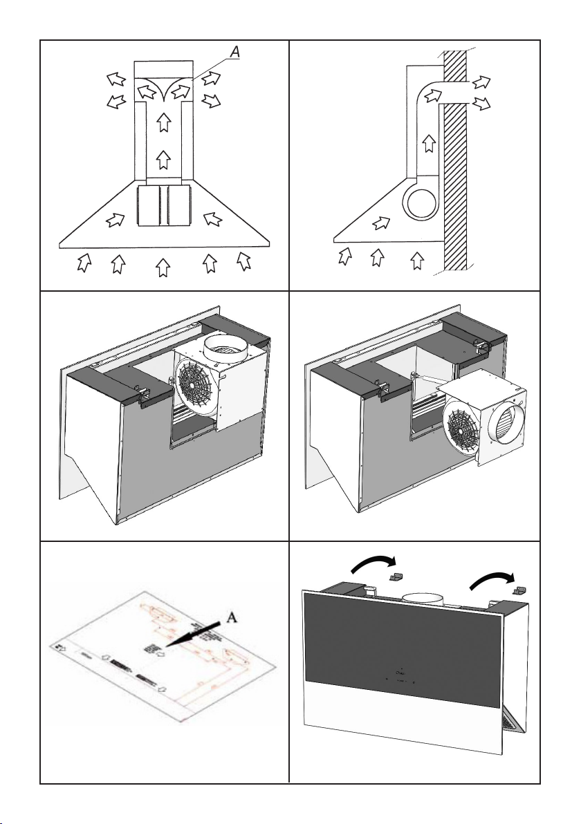
The TAU760 extractors have been designed to
have the possibility of directing the air outlet to
the rear of the appliance, instead of out of the
top; if you choose to use this function, it is
necessary to remove the x10 screws from the
motor unit (Fig. 3), remove the motor unit and
rotate it in such a way to direct the air outlet
spigot towards the rear side of the appliance
(Fig. 4); then place the motor unit back into
position and tighten the screws previously
removed.
By using the drilling template (Fig .5A), drill the
holes for the wall bracket installation;
Appliances shall be installed at a minimum
distance of 500mm from the cooking surface.
Drill the remaining holes indicated by the hole
drilling template.
Fix the brackets to the wall, by using the wall
plugs and screws supplied with the product;
Hang the body (Fig. 6) to the wall brackets
previously fixed.
Tighten the two screws into the wall bracket
(Fig. 7A), as they are necessary for the
appliance to secure to the wall. Then check
that the hood is perfectly flush with the wall,
otherwise adjust the screws shown in Fig.7B.
Tighten the screw if you need to lift up the
corresponding side, or unscrew it, in case you
need to reduce the height.
TAU760
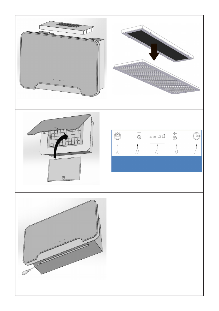
Remove the metal grease filters, which are
magnetically secured to the appliance, by using
either a hand tool or a knife edge. Act on the
slot found in the filter sides, as shown in Fig. 8.
Fix the appliance to the wall with the screws
provided, as per Fig. 11.
NOV800
Open the front panel by pulling the lower side
upwards, as shown in Fig. 7, then remove the
grease filter. Fix the appliance to the wall with
the screws provided, as per Fig. 11.
Vented mode
Using the supplied wall plugs and screws, fix the
chimney support bracket (Fig. 12) to the wall
and/or the ceiling. The bracket must be fixed in a
central position in respect of the air outlet flange.
Connect the motor air outlet flange to the ducting
by using a suitable pipe. Perform the electric
connection. Place the two ornamental pipes on
the hood body; lift the internal pipe up until it
reaches the ceiling;
then x it to the pipe bearing bracket, by using the
two self-threaded screws provided.
Recirculation mode
Install the air outlet grill above the hood in the
relative seat (refer to Fig. 13). The stainless steel
chimneys are not necessary.
TAU760
The charcoal filters are installed directly onto the
rear side of the grease filters (see Fig. 14).
NOV800
The charcoal filters are installed as shown in
Fig. 15, by fitting it into its seat which is found
just behind the metal grease filter.
Charcoal filters should be replaced accordingly
to the effective use of the hood, and in any case
at least once every 6 months.
To purchase replacement charcoal filters, please
visit www.caple.co.uk or call our sales office on
0117 938 1900.
Note: Charcoal filters do not come included, and
must be ordered separately if required.

7
WORKING
Control panel
A: Light switch On/Off
B: Reduce speed / OFF
C: Selected speed indicator
D: ON / increase speed
E: 10 minute timer
The touch control key allows the function desired
by touching the relative key.
If the electrical power supply to the product is
cut, 15 seconds are needed for self diagnostics
after the functions are restored.
In the meanwhile, its operation may be incorrect.
TIMING
As a result of the new EU65 “Energy label” and
EU66 “ Ecodesign” regulations issued by the
European Commission, which came into force as
from January 1st, 2015 , our products have been
adapted to comply with these new requirements.
All of the models complying with the energy
label requirements, are equipped with new
electronics including a timer device for suction
speeds control, when the air capacity exceeds
650m³/h.
Internal motor models, with maximum air capacity
higher than 650m³/h, are equipped with a timer de-
vice that automatically switches the suction speed
from 4th to 3rd speed, after 6 minutes operation.
The energy consumption of the appliance in stand
– by mode is lower than 0.5W.
An accurate maintenance guarantees good
functioning and long lasting performance.
Particular care is due to the grease filter. It can
be removed by following the instructions below.
The saturation of the filter is indicated by the
flashing speed indicators (Fig. 16C). Press the
timer button to reset.
The grease filter needs cleaning regularly by
either hand washing or in the dishwasher. We
recommend cleaning every two months at least
or depending on its use.
In case the appliance is used in Recirculation
mode, the active charcoal filter needs to be
periodically replaced.
To clean the appliance itself tepid water and
neutral detergent are recommended, while
abrasive products should be avoided.
The power cord shall be replaced by
authorized personnel only.
Substitution of the LED bar:
Using an appropriate tool, remove the LED
bar from its seat (refer to Fig. 17), disconnect it
electronically using the appropriate connector
then substitute it with a LED bar with same
characteristics.
MAINTENANCE

1
8
2
4
56
3

7
9
11 12
10
8
9

10
13
17
16
14
15

11

90007110111 - 06/18
Caple Service
Fourth Way
Avonmouth
Bristol
BS11 8DW
t: 0117 938 7420
www.caple.co.uk
Please keep this instruction manual for future
reference
This manual suits for next models
1
Table of contents
Other Caple Scrubber manuals
Popular Scrubber manuals by other brands

Weller
Weller Zero Smog TL Translation of the original instructions

Nilfisk-Advance
Nilfisk-Advance C446 Instructions for use

Tennant
Tennant T12 Instruction bulletin

Advance acoustic
Advance acoustic Adhancer56316000(W28-C) Service manual

Sealey
Sealey EFS/93.V4 instructions

Clemas & Co
Clemas & Co GANSOW 61BF 57 Service and parts manual