6
INSTALLATION
Before installing the appliance, make sure that
none of the parts is damaged in any way.
In case of damaged parts, contact your retailer
and do not proceed with installation.
Read all of the following instructions with care be-
fore installing the appliance.
- Use an air outlet pipe of the shortest possible
length.
- Limit the number of pipe bends.
- Use a material approved by standards and re-
gulations.
- Avoid any sudden changes in pipe section (re-
commended constant diameter: 150 mm or equal
surface area).
- The manufacturer shall not respond for air ca-
pacity or noise problems due to non- compliance
with above mentioned instructions, and no war-
ranty shall be given.
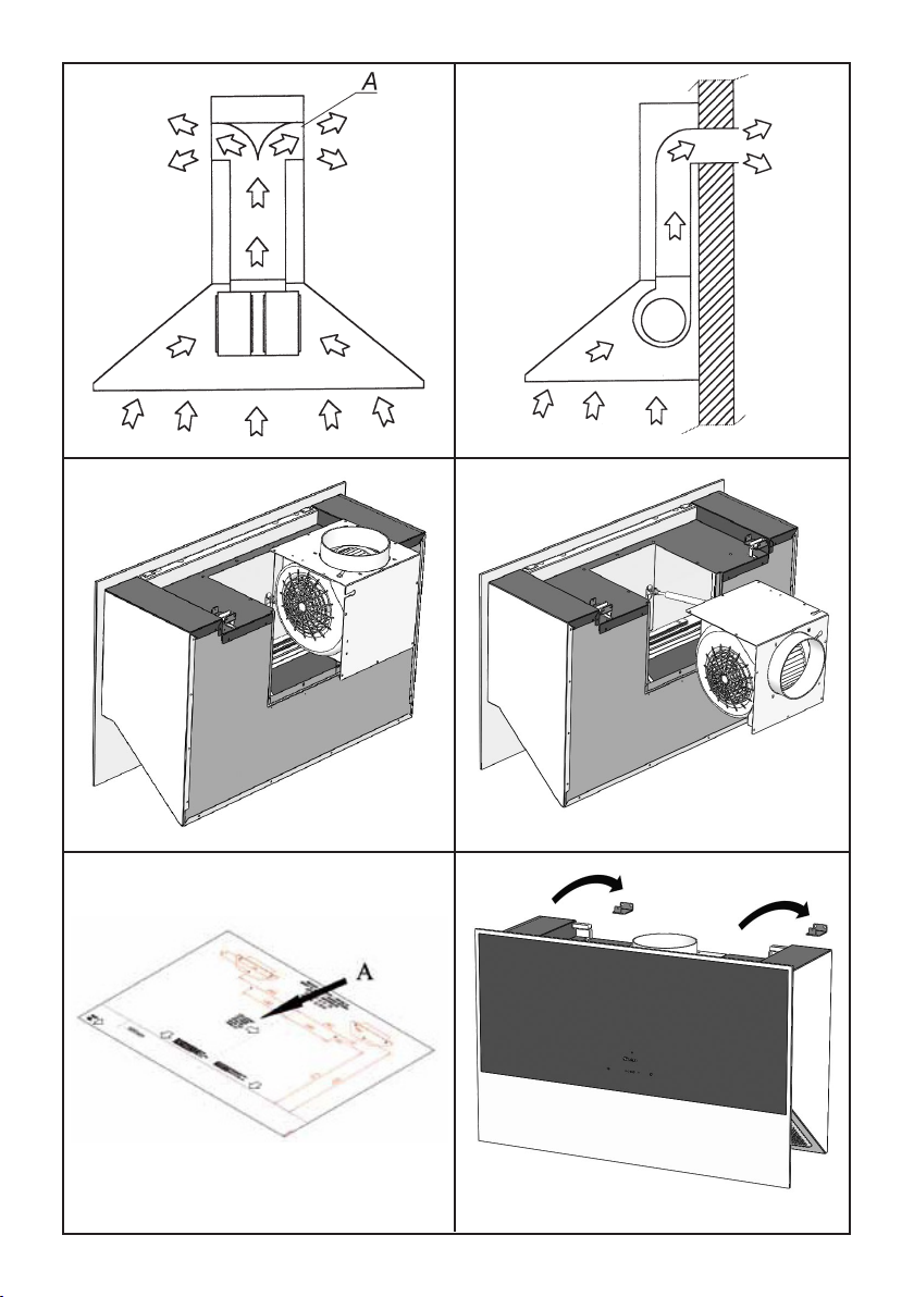
All the models SLTC110 have been designed in
order to have the possibility of directing the air
out-let in the rear side of the appliance; if you
chose to use this function, it is necessary to re-
move the no. 10 screws of the sucking unit sup-
port (g. 3 ), take out the sucking unit and rotate
it in such a way to direct the air out-let nozzle to-
wards the rear side of the appliance (g. 4); then
place the sucking unit in its seat again and tighten
the screws previously removed.
By using its drilling template (g. 5A), drill the ho-
les for the wall bracket installation;
Appliances shall be installed at a minimum di-
stance of 500mm from the cook-top.
Drill the remaining holes indicated by the hole-
drilling template.
Fix the brackets to the wall, by using the screw
anchors and screws supplied with the product;
Hang the body (Fig. 6) to the wall brackets pre-
viously xed.
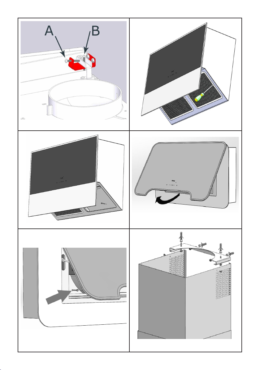
Tighten the two screws into the wall bracket (g.
7A), as they are necessary for the appliance to
adhere to the wall. Then check that the hood is
perfectly ush with wall, otherwise act on the
screws shown in g. 7B.
Tighten the screw if you need to lift up the corre-
sponding side, or unscrew it, in case you need to
reduce the height.
SL110
Remove the metal grease lters, which are ma-
gnetically secured to the appliance, by using ei-
ther a hand tool or a knife edge. Act on the slot
found in the lter sides, as shown in Fig.8.
Fix the appliance to the wall with the screws pro-
vided, as per g. 11.
SL111
Open the front panel by pulling the lower side up-
wards, as shown in g. 7, then remove the grease
lter. Fix the appliance to the wall with the screws
provided, as per g. 11.
Sucking version
Using the supplied wall plugs and screws, x the
tube support bracket (Des. 12) to the wall and/or
the ceiling. The bracket must be xed in a central
position in respect of the air outlet ange.
Connect the motor air-outlet ange to the exhaust
hole, by using a suitable pipe. Perform the elec-
tric connection. Place the two ornamental pipes
on the hood body; lift the internal pipe up until it
reaches the ceiling;
then x it to the pipe bearing bracket, by using the
two self-threaded screws provided.
Filtering version
Install the air outlet grill above the hood in the
relative seat (refer to Fig. 13). The stainless steel
chimneys are not necessary.
SL110
The charcoal lter is installed directly on the gre-
ase lter rear side (see Fig. 14).
SL111
The charcoal lter is installed as shown in g. 15,
by tting it into its seat which is found just behind
the metal grease lter.
Charcoal lters should be replaced accordingly
to the effective use of the hood, and in any case
at least once every 6 months.