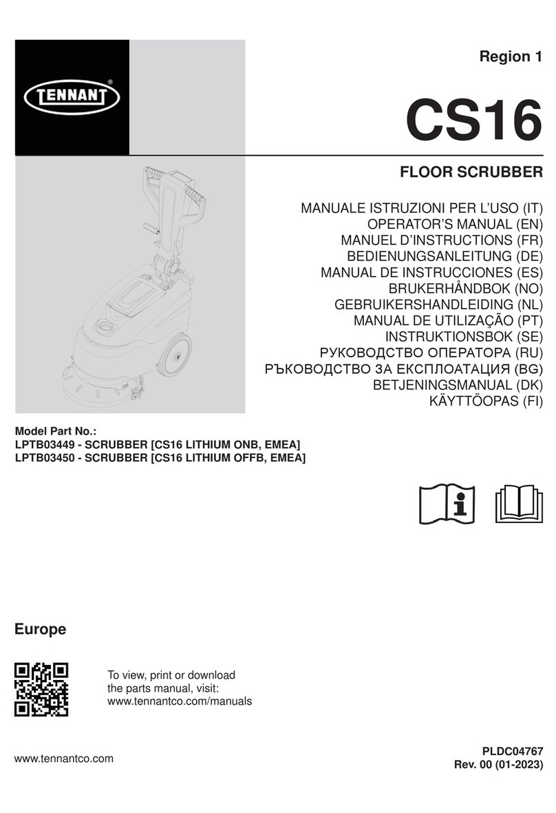
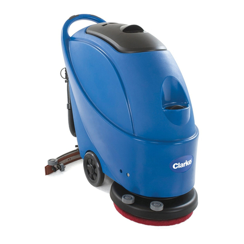
Tennant CS16 Operating manual

PLDC04626
REVISION DATE
March 11, 2022
TECHNICAL OFFICE
TECHNICAL SERVICE MANUAL
Stavale
CS16
DATE
March 11, 2022


WARNING
:
T
r
i
gger
i
ng o
f
th
e
b
rus
h
mo
t
or
th
erma
l
,
i
n
t
errup
ti
on o
f
th
e
b
rus
h
mo
t
or
an
d
vacuum mo
t
or
f
uses, ma
lf
unc
ti
on
(i
n
t
errup
t
e
d
ca
bl
e
)
o
f
th
e
b
rus
h
mo
t
or an
d
vacuum mo
t
or power ca
bl
es are no
t
di
sp
l
aye
d
on
th
e
d
as
hb
oar
d
.
PLDC04626
REVISION 00
March 11, 2022
TECHNICAL OFFICE
Stavale
ALARM CODES DISPLAYED
Error: BRUSH SHUTDOWN
On display: 2 quick flashes of brush LED ref. 3
Short-circuit protection error.
This occurs when excessive peak current is detected.
Check that the brush motor wiring is not short-circuited.
Manually check that the brush motor rotates freely and without effort.
Error: SUCTION SHUTDOWN
On display: 2 fast flashes of suction LED ref. 4
Short-circuit protection error.
This occurs when excessive peak current is detected.
Check that the suction motor wiring is not short-circuited.
Manually check that the suction motor rotates freely and without effort.
1
234 5
Error: BRUSH I²T
On display: 2 slow flashes of brush LED ref. 3
Brush motor overload error.
Check that the brushes and the drive are not rubbing anywhere.
Check brush motor current draw.
Error: SUCTION I²T
On display: 2 slow flashes of suction LED ref. 4
Suction motor overload error.
Check check that the suction motor rotor rotates freely.
Check brush motor current draw.
*

Error: MAXIMUM TEMPERATURE
On display: fast, continuous flashing of brush LED ref. 3 and suction LED ref. 4 simultaneously.
Power board overheating error.
To restore the functions switch the machine off and wait around 15 minutes until the power board
cools down.
Check brush motor and suction motor current draw.
Error: BRUSH THERMAL PROTECTOR
On display: 4 consecutive flashes of brush LED ref. 3.
Brush motor overheating error.
Brush motor thermal protector tripped
The board cuts off power to the brush motor.
Wait for the brush motor to cool down and the thermal protector inside the motor to reset.
Warning: BATTERIES CHARGED
On display: 5 consecutive flashes of yellow battery LED ref. 1.
Charged batteries warning.
Disconnect the battery charger.
Warning: BATTERIES DISCHARGED
On display: 6 consecutive flashes of yellow battery LED ref. 1.
Discharged batteries warning.
Recharge the batteries.
Error: BRUSH MOTOR SHUTDOWN
On display: 11 consecutive flashes of yellow battery LED ref. 1.
Brush motor shut down by power board, due to discharged battery with
voltage at minimum set threshold of 21.9 Volts.
Recharge the batteries.
Error: SUCTION MOTOR SHUTDOWN
On display: 12 consecutive flashes of yellow battery LED ref. 1.
Brush motor shut down by power board, due to discharged battery with voltage at minimum safety
threshold of 21.5 Volts.
Recharge the batteries.
Warning: BATTERY CHARGER ON
On display: 7 consecutive flashes of yellow battery LED ref. 1.
Batteries charging warning.
Wait until batteries are fully recharged.

Information - I²T:
The overload error (I²T)is shown when the power board needs to deliver current that exceeds the set
maximum value.
A
ctivation of the power board shuts down the motor that caused the error, and is signalled by the
flashing of the LED on the instrument panel corresponding to the motor in question.
For the suction motor, the limit is 30 Amperes (exceeding 30A) for a maximum of 20 seconds.
For the brush motor, the limit is 15 Amperes (exceeding 15A) for a maximum of 20 seconds.
The problem can be reset by switching the machine off and on again. If the error occurs again, check the
Information - MAXIMUM TEMPERATURE ERROR:
The overheating error on the brush motor and suction motor power board is shown when the board
temperature exceeds the maximum set value.
A
ctivation of the power board shuts down both motors, regardless of which caused the overheating, and
is signalled by fast and continuous flashing of the LEDs corresponding to both the brush and suction
motor.
Information - SUCTION IN REMOTE MODE:
Can be activated starting from serial number 8000209102
Pressing the suction button ref. 4 for around 5 seconds, the suction motor will start without acting on the
brush control lever.
Information - ERRORS NOT DISPLAYED:
If the machine fails to start or the functions cannot be activated, without any errors shown on the display,
the problem could be due to a broken flat cable, a damaged display board or a short-circuit on the power
board.
In these cases to restore normal operation, replace the faulty component (flat cable, display board,
power board), which can be identified by inspecting the component visually, or replacing them one-by-
Information - SHUTDOWN ERROR:
If activated due to "short circuit" or "excessive peak current" detected by the power board, the problem
may involve the brush and/or suction motor wiring or motor power supply or the actual power board
itself.
In the shutdown error involves the motors or the motor wiring, the electronic control board stops the
function and signals the error via the LED on the instrument panel.

Sub
j
ect Page
ABRUSH HEAD
A1 MEASURING BRUSH MOTOR CURRENT DRAW 2
A1.1 Measuring brush motor current draw on the CS16 Battery 3
A1.2 Replacing the brush motor’s carbon brushes on the CS16 Battery 5
A1.3 Replacing the brush motor’s carbon brushes on the CS16 Cord 9
A2 REMOVING THE BRUSH MOTOR - BRUSH HEAD 13
A2.1 Removing the brush motor from the CS16 Battery 14
A2,2 Removing the brush motor from the CS16 Cord 18
A2.3 Removing the brush head from the CS16 B and CS16 Cord 19
A2.4 Replacing the brush motor’s thermal protector 21
BSUCTION UNIT - TANKS
B1 SUCTION MOTOR 25
B1.1 Measuring suction motor current draw on the CS16 Battery 26
B1.2 Removing the suction motor from the CS16 Battery 28
B1.3 Replacing the suction motor carbon brushes on the CS16 Battery 30
B1.4 Removing the suction motor from the CS16 Cord 32
B1.5 Replacing the suction motor carbon brushes on the CS16 Cord 33
B2 SQUEEGEE UNIT 35
B2.1 Adjusting the squeegee 36
B2.2 Replacing the squeegee flaps 37
B3 CLEANING FILTERS AND HOSES - TESTING THE SOLENOID VALVE AND FLOAT 41
B3.1 Testing the solenoid valve 42
B3.2 Testing and replacing the solenoid valve on “B” version machines 44
B3.3 Checking the condition of the float 48
B3.4 Cleaning the filters, hoses and solution dispensing cock 49
DINSTRUMENT PANEL/POWER BOARD-BATTERY CHARGER-ELECTRICAL CIRCUIT
D1 INSTRUMENT PANEL BOARD - POWER BOARD 55
D1.1 Replacing the function control card on “B” and “C” version machines 56
D1.2 Testing the function control card on “B” and “C” version machines 59
D1.3 Replacing the power board on “Battery” version machines 62
D1.4 Testing the power control card on “Battery” version machines 66
D1.5 Replacing the power control card on Cord type machines 69
D1.6 Testing the power control card on Cord type machines 73
D2 BATTERY CHARGER 82
D2.1 Replacing the battery charger 83
D2.2 Setting the battery charger charging curve 88
D3 WIRING DIAGRAMS 96
D3.1 Electric wiring diagram for type Battery versions 96
D3.2 Electric wiring diagram for type Cord versions 97
EERROR CODES - TROUBLESHOOTING
E1 DISPLAY OF ERROR CODES 99
E1.1 Error codes for the fuction control card on Battery type machines 99
E2 TROUBLESHOOTING 105
E2.1 Troubleshooting 105
REVISIONS - UPDATES 109
OPTIONS
INDEX
PLDC04626
REVISION 00
March 11, 2022
TECHNICAL OFFICE
Stavale

In line with the company's policy of constant product development and updating,
the Manufacturer reserves the right to make modifications without warning.
Although your machine may differ appreciably from the illustrations in this document,
safety and the information contained in this manual are guaranteed.
WARNINGS
! DANGER
could cause damage to the machine or work environment or financial loss.
i INFORMATION
Indicates particularly important instructions.
Indicates the need for attention in order to avoid a series of consequences which
could cause death or damage to the health of the operator.
*
*
WARNING
Indicates the need for attention in order to avoid a series of consequences which

PLDC04626
REVISION 00
March 11, 2022
TECHNICAL DEPT.
Stavale
March 11, 2022 1/109
A BRUSH HEAD
*
*
WARNING!
Go to the designated draining area and empty the
solution and collection tanks using the drain plugs
and the hoses provided.
Position the machine on a flat floor, and place wedges
under the wheels to stop it moving.
Switch the machine off and disable all functions by
pressing the “On–Off” button on the control panel.
Disconnect the machine’s electrical system by removing
the main fuse F1, or by disconnecting the terminals
from the battery poles (battery powered machines),
or by removing the plug from the mains power socket
(mains powered machines).
i INFORMATION
Important information
In this Service Manual, the terms RIGHT and LEFT are
used to indicate the sides of the machine. They
always refer to the direction of travel.
In this Service Manual, the machine version (CS16 B
= battery, CS16 C = corded)may appear between
brackets “( )”. This indicates that the instruction in
question refers only to the version specified.

PLDC04626
REVISION 00
March 11, 2022
TECHNICAL DEPT.
Stavale
March 11, 2022 2/109
A1 MEASURING BRUSH MOTOR CURRENT DRAW
On the scrubber CS16, the brush motors of type battery versions and cord type
versions are very similar. Apart from the power source (24 V DC for battery versions
and 230V AC for “C” versions), the differences lie in the motors’ maximum current
draw and in the type of connections. The motors of mains powered versions feature
waterproof terminals to provide increased protection against electric shock.
i
CS16 Battery CS16 Cord
PHOTO 1

PLDC04626
REVISION 00
March 11, 2022
TECHNICAL DEPT.
Stavale
March 11, 2022 3/109
A1.1 Measuring brush motor current draw on the CS16 Battery
1Make sure that the batteries on the machine are fully charged (24V ± 1V).
2Use a clamp-on ammeter with a full scale reading of at least 200 A (amperes) as shown below.
3Move the machine to the tank draining area, and completely empty the collection tank A.
4Make sure that the solution tank contains only a small amount of solution before you start.
5Move the machine to a flat, dry and smooth floor.
6Make sure that you have enough room around the machine to perform the measurement safely.
7Unhook the hoses and lift up and remove the collection tank Ato access the cables B of the brush motor.
8Set the clamp-on ammeter to measure amperes (A) of DC current, and clamp it to the red cable.
9Press the “On-Off” button to switch the machine on, and press button Cto switch off suction.
10 Pull in the control lever Don the handle. Read and record the current draw of the brush motor.
PHOTO 2
A
B
PHOTO 3
PHOTO 4
D
C
25A

PLDC04626
REVISION 00
March 11, 2022
TECHNICAL DEPT.
Stavale
March 11, 2022 4/109
On the CS16 Battery, the brush motor is powered by the power control card.
This imposes a current ramp, so you are unlikely to see in-rush current peaks.
For this reason, always wait a few seconds for current draw to stabilise before taking
the reading.
To obtain current draw readings that can be compared to those in the table below,
make sure that the machine is fitted with a standard brush and that the floor surface
is neither excessively rough nor excessively smooth.
11 Completely fill the solution tank and measure current draw under full load.
12 Pull in the control lever Don the handle. Read and record the current draw of the brush motor.
13 Now lift the brush off the floor by pulling down on the handle and tilting the machine backwards.
14 Pull in the control lever Don the handle. Read and record the current draw of the brush motor under zero
load.
15 Provided the current draw values lie between the minimum and maximum values specified in the table
below, the motor is functioning correctly. You can now remove the ammeter and replace the collection tank.
16 If the measurements do not correspond to those specified, proceed as follows.
16a If no-load current draw (brush raised) is correct, but full load current draw (brush on floor and solution tank
full) is too high, first check that the solution is being dispensed properly. Also try moving to a smoother floor
surface. Check that battery voltage has not fallen much under 24 V. Check the motor’s carbon brushes and
replace if necessary.
16b If current draw is too high at full load and at zero load, check that the brush rotates freely without rubbing
against the brush cover or any part of the frame. Check also that the gear unit is properly lubricated. Check
the motor’s carbon brushes and replace if necessary.
16c If the above checks have not revealed the problem, replace the brush motor with a new one.
Current draw A (amperes) Min Max
Light load (standard brush – solution tank almost empty) 7 A 9 A
Full load (standard brush – solution tank full) 9 A 11 A
No load (brush raised off floor) 2 A 3.5 A
*
*
PHOTO 5

PLDC04626
REVISION 00
March 11, 2022
TECHNICAL DEPT.
Stavale
March 11, 2022 5/109
A1.2 Replacing the brush motor’s carbon brushes on the CS16 B
Disassembly
1Move the machine to the tank draining area, and empty the solution tank and the collection tank.
2Move the machine to a flat, dry floor. For convenience, use a fork lift if one is available.
3Remove the brush and the collection tank.
4Disconnect and remove the batteries from the battery compartment.
5Lower the squeegee by means of its operating lever.
6Close the solution dispensing cock A, at the bottom left of the tank.
7Turn the handle A1 of the cock Aclockwise to shut off the solution supply.
8Disconnect the hose Bfrom the cock A.
9Cut the plastic straps Cfixing the rear of the tank to the frame.
10 Remove the screw Dsecuring the solution tank to the bottom front of the machine frame.
B
C
A1
A
PHOTO 7
D
PHOTO 8
D
PHOTO 6

PLDC04626
REVISION 00
March 11, 2022
TECHNICAL DEPT.
Stavale
March 11, 2022 6/109
11 Lift from its seat the two fuse holders.
12 Detach the cable from the squeegee mounting by unscrewing the screw E.
13 Lift the solution tank up to the brush motor.
14 Pull the machine frame and brush motor mounting away from the solution tank.
15 Remove the screw Gholding the metal strap Hin place, to protection of carbon motor brushes I.
16 Disconnect the brush motor’s four carbon brushes I, and pull them out one by one to check their condition.
17 Use a long nose pliers to disconnect the fast-on connector of each carbon brush I.
II
PHOTO 11
N
H
G
PHOTO 10
PHOTO 9
E

PLDC04626
REVISION 00
March 11, 2022
TECHNICAL DEPT.
Stavale
March 11, 2022 7/109
18 Use a suitable hook to pull away the spring clip Lwhile lifting the carbon brush out by its cable.
19 Check that the dimensions of the carbon brush Ilie within the tolerances given in the figure below. The brush
must have a minimum length of 8.0 mm / 0,31 in.
20 Check the sliding contact surface I1 of the carbon brushes Ifor wear or damage. The surface must not be
badly worn or burned.
21 When fitting new carbon brushes, compare the new ones with the old ones, or check them against the
dimensions given in the figure below. Only the length must be different.
Always replace all four carbon brushes at the same time.
When fitting the carbon brushes, make sure that they slide freely in their seats.
PHOTO 12
L
I
*
*
*
*
18.9 ± 0.1 mm PP
I1
I
I
I
6.9 ± 0.1 mm 13.9 ± 0.1 mm
PHOTO 13
0.27 ± 0.004 in 0.55 ± 0.004 in
0.74 ± 0.004 in 0.31 in

PLDC04626
REVISION 00
March 11, 2022
TECHNICAL DEPT.
Stavale
March 11, 2022 8/109
22 Blow the inside of the motor clean with a jet of compressed air, paying particular attention to the area around
the carbon brushes and to the part of the rotor Mwith which the carbon brushes come into sliding contact.
23 Check the rotor Mfor wear, paying particular attention to the area of contact with the carbon brushes.
24 When repositioning the metal strap Hover the carbon brushes I, align the notch Nin the strap with the
corresponding reference on the motor body.
25 Arrange the clamp H1 of the metal strap Has shown in the figure below when reassembling.
Reassembly
1When fitting carbon brushes, make sure that all four slide freely in their seats.
2Always check the rotor M for wear before fitting new carbon brushes.
3To fit the new carbon brushes and reassemble the machine, repeat the steps for disassembly in reverse
order.
M
PHOTO 14
H
H
PHOTO 15
N
H
1

PLDC04626
REVISION 00
March 11, 2022
TECHNICAL DEPT.
Stavale
March 11, 2022 9/109
A1.3 Replacing the brush motor’s carbon brushes on the CS16 C
Disassembly
1Make sure that the machine is disconnected from the electricity supply.
2Move the machine to the tank draining area, and empty the solution tank and the collection tank.
3Move the machine to a flat, dry floor. For convenience, use a fork lift if one is available.
4Remove the brush and the collection tank. Lower the squeegee.
5Close the solution dispensing cock A, at the bottom left of the tank.
6Turn the handle A1 of the cock A clockwise to shut off the solution supply.
7Disconnect the hose B from the cock A.
8Cut the plastic straps C fixing the rear of the tank to the frame.
9Remove the screw D securing the solution tank to the bottom front of the machine frame.
10 Disconnect the brush motor’s power connector E(EMI Filter is not visible in this photo).
11 Tilt the handle back through about 45°. 45°
DD
PHOTO 17
C
E
PHOTO 18
A1
ABPHOTO 16

PLDC04626
REVISION 00
March 11, 2022
TECHNICAL DEPT.
Stavale
March 11, 2022 10/109
12 Arrange the motor cable (power E) so that they are not
pulled when the motor is moved away from the solution tank.
13 Tip the machine rearwards, until the handle rests on the
floor.
14 Detach the cable from the squeegee mounting elastic ring F.
15 Pull the machine frame and brush motor mounting away from the solution tank.
16 Remove the screw Gholding the metal strap Iin place, to protection of carbon motor brushes L.
17 Disconnect the brush motor’s two carbon brushes L, and pull them out one by one to check their condition.
18 Use a long nose pliers to disconnect the fast-on connector of each carbon brush from the circuit board.
F
PHOTO 20
E
PHOTO 19
I
I
G
PHOTO 21
PHOTO 22
L
L

PLDC04626
REVISION 00
March 11, 2022
TECHNICAL DEPT.
Stavale
March 11, 2022 11/109
19 Use a suitable hook to pull away the spring clip M while lifting the carbon brush L out by its cable.
20 Check that the dimensions of the carbon brush L lie within the tolerances given in the figure below. The
brush must have a minimum length of 8.0 mm / 0,31 in.
21 Check the sliding contact surface L1 of the carbon brush L for wear or damage. The surface must not be
badly worn or burned.
22 When fitting new carbon brushes, compare the new ones with the old ones, or check them against the
dimensions given in the figure below. Only the length must be different.
Always replace both carbon brushes at the same time.
When fitting the carbon brushes, make sure that they slide freely in their seats.
PHOTO 23
M
L
*
*
*
*
18.9 ± 0.1 mm PP
L
L
IL
13.9 ± 0.1 mm6.9 ± 0.1 mm
L1
PHOTO 24
0.31 in
0.74 ± 0.004 in
0.27 ± 0.004 in 0.55 ± 0.004 in

PLDC04626
REVISION 00
March 11, 2022
TECHNICAL DEPT.
Stavale
March 11, 2022 12/109
23 Blow the inside of the motor clean with a jet of compressed air, paying particular attention to the area around
the carbon brushes and to the part of the rotor Nwith which the carbon brushes come into sliding contact.
24 Check the rotor Nfor wear, paying particular attention to the area of contact with the carbon brushes.
25 When repositioning the metal strap I over the carbon brushes L, align the notch Oin the strap with the
reference on the motor body.
26 Arrange the clamp I1 of the metal strap Ias shown in the figure below when reassembling.
Reassembly
1When fitting carbon brushes, make sure that they both slide freely in their seats.
2Always check the rotor Nfor wear before fitting new carbon brushes.
3To fit the new carbon brushes and reassemble the machine, repeat the steps for disassembly in reverse
order.
N
PHOTO 25
O
I
PHOTO 26
O
O
O
O
O
O
O
O
O
O
O
O
O
O
O
O
O
O
O
O
O
O
O
O
O
O
O
I1

PLDC04626
REVISION 00
March 11, 2022
TECHNICAL DEPT.
Stavale
March 11, 2022 13/109
A2 REMOVING THE BRUSH MOTOR AND BRUSH HEAD
Removing the CS16 brush motor and brush head is a quick and easy operation. It is
nevertheless important to take careful note of the polarity of the motor’s power
cables, to avoid problems caused by the brush that could compromise the washing.
PHOTO 27
Other manuals for CS16
4
Table of contents
Other Tennant Scrubber manuals

Tennant
Tennant 800D User manual

Tennant
Tennant T5 User manual

Tennant
Tennant LPTB03175 User manual

Tennant
Tennant 810D User manual

Tennant
Tennant T1 User manual
Tennant
Tennant 8010 User manual

Tennant
Tennant M17 Series Training manual

Tennant
Tennant 7200 Training manual

Tennant
Tennant 9021147 User manual

Tennant
Tennant T7 User manual

Tennant
Tennant 550 User manual

Tennant
Tennant M17 Series User manual

Tennant
Tennant 7200 User manual

Tennant
Tennant 7100 Training manual

Tennant
Tennant T16 Training manual
Tennant
Tennant T191 User manual

Tennant
Tennant CS16 User manual

Tennant
Tennant Speed Scrub ES KIT 2701 User manual

Tennant
Tennant F 170 User manual

Tennant
Tennant M17 Series Training manual