Car-Interface.com c.LOGiC lite-Interface User manual

Version 20.09.2017 CI-C1-C25
c.LOGiC lite-Interface
CI-C1-C25
compatible with navigation systems
Mercedes Benz
Comand 2.5
Product features
• full plug and play multimedia interface
• 1 AV-input with separate IR-control channel
• control of after-market devices, e.g. DVB-T tuner, DVD-player, DVD-changer, …
• after-market rear-view camera input activation
• automatic switching to rear-view camera input (only from c.LOGiC-mode)
• rear-view camera power (+12V max. 1A)
• power on remote out trigger signal (+12V max. 1A) to switch on connected devices
• video-in-motion

Version 20.09.2017 CI-C1-C25
Page1
Contents
1. Prior to Installation
1.1. Delivery contents
1.2. Check compatibility of vehicle and accessories
2. Connection schema
3. Installation
3.1. Connections to the Comand
3.2. Interconnecting Interface-box and harnesses
3.3. Connecting peripheral devices
3.3.1. AV-source
3.3.2. Installing AV-source’s IR-sensor additionally
3.3.3. After-market rear-view camera
4. Operation
4.1. Activation of the video-in-motion function
4.2. Selecting the c.LOGiC as current AV-source
4.3. Assigning device control
4.4. Button assignment table
4.5. Picture settings
4.6. Audio settings
5. Specifications
Appendix A –Device control table

Version 20.09.2017 CI-C1-C25
Page2
Legal Information
By law, watching moving pictures while driving is prohibited, the driver must not be
distracted. We do not accept any liability for material damage or personal injury resulting,
directly or indirectly, from installation or operation of this product. This product should only
be used while standing or to display fixed menus or rear-view-camera video when the
vehicle is moving, for example the MP3 menu for DVD upgrades.
Changes/updates of the vehicle’s software can cause malfunctions of the interface. We
offer free software-updates for our interfaces for one year after purchase. To receive a free
update, the interface must be sent in at own cost. Labor cost for and other expenses
involved with the software-updates will not be refunded.
1. Prior to installation
Read the manual prior to installation. Technical knowledge is necessary for installation. The
place of installation must be free of moisture and away from heat sources.
1.1. Delivery contents
If remote function for the connected devices shall be used, additionally an IR-
remote cable and Y-adapter are needed, see chapter AV-source .
Take down the SW-version and HW-version of the interface boxes, and store this
manual for support purposes.
Harness
C1C-ME25
Interface-Box
C1C-M01
HW_____ SW_____

Version 20.09.2017 CI-C1-C25
Page3
1.2. Check compatibility of vehicle and accessories
Requirements
Vehicle CL-class (C215) til 08/2002, S-class (W220) til 08/2002
Navigation Comand 2.5
Limitations
Factory-TV-tuner Must NOT be installed.
After-market rear-view cam Automatic switching to camera only works from c.LOGiC-mode

Version 20.09.2017 CI-C1-C25
Page4
2. Connection schema
3. Installation
Switch off ignition and disconnect the vehicle’s battery! If according to factory rules
disconnecting the battery has to be avoided, it is usually sufficient to put the vehicle in
sleep-mode. In case the sleep-mode does not show success, disconnect the battery with a
resistor lead.

Version 20.09.2017 CI-C1-C25
Page5
17
18
A
B
8
4
3.1. Connections to the Comand
Place of installation is behind the Comand. Remove the head-unit from the dash-board.
If female 8pin C1 connector of factory harness exists, transfer pins from female 8pin
C1 connector of C1C-ME25 to corresponding slots of female 8pin C1 connector of
factory harness. If slots are occupied remove and isolate factory wires (take notes
before removing).
Otherwise use female 8pin C1 connector of C1C-ME25 instead of factory connector.
Connect yellow loose wire (CAN high) C1C-ME25
to pin 18 of chamber C2. Connect loose blue wire
(CAN low) of C1C-ME25 to pin 17 of chamber C2.
Connect loose red wire of C1C-ME25 to pin 4
of chamber A (+12V battery power).
Connect loose black wire of C1C-ME25 to pin 8
of chamber A (ground).
Plug female 8pin C1 connector of factory harness
(if not existing, of C1C-ME25) into C1 slot of
Comand’s male system connector.
Plug male 5pin DIN connector of harness C1C-ME25 into female 5pin DIN socket on
the Comand’s rear.

Version 20.09.2017 CI-C1-C25
Page6
3.2. Interconnecting Interface-box and harnesses
Plug harness C1C-ME25 into 12pin Molex of Interface-box C1C-M01.
3.3. Connecting peripheral devices
It is possible to connect one after-market AV-source and an after-market rear-view camera
to the c.LOGiC Interface.
Before final installation of the peripheral devices, we recommend to test-run the c.LOGiC
functions to detect incompatibility of vehicle, navigation, factory accessories or peripheral
devices as soon as possible.

Version 20.09.2017 CI-C1-C25
Page7
3.3.1. AV-source
The c.LOGiC interface has the possibility to connect and remotely control by navigation
buttons one pre-programmed device. The device list in the device control table (Appendix A)
shows the pre-programmed remote channels and the related IR-remote cables STA-xxx
which must be ordered separately for the control of the device.
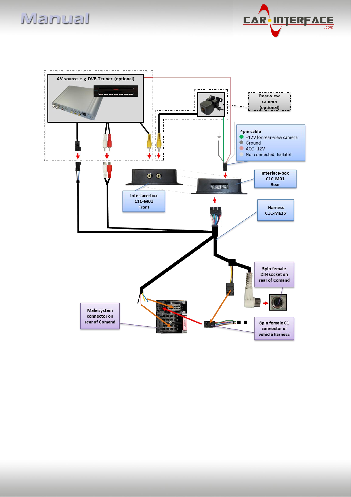
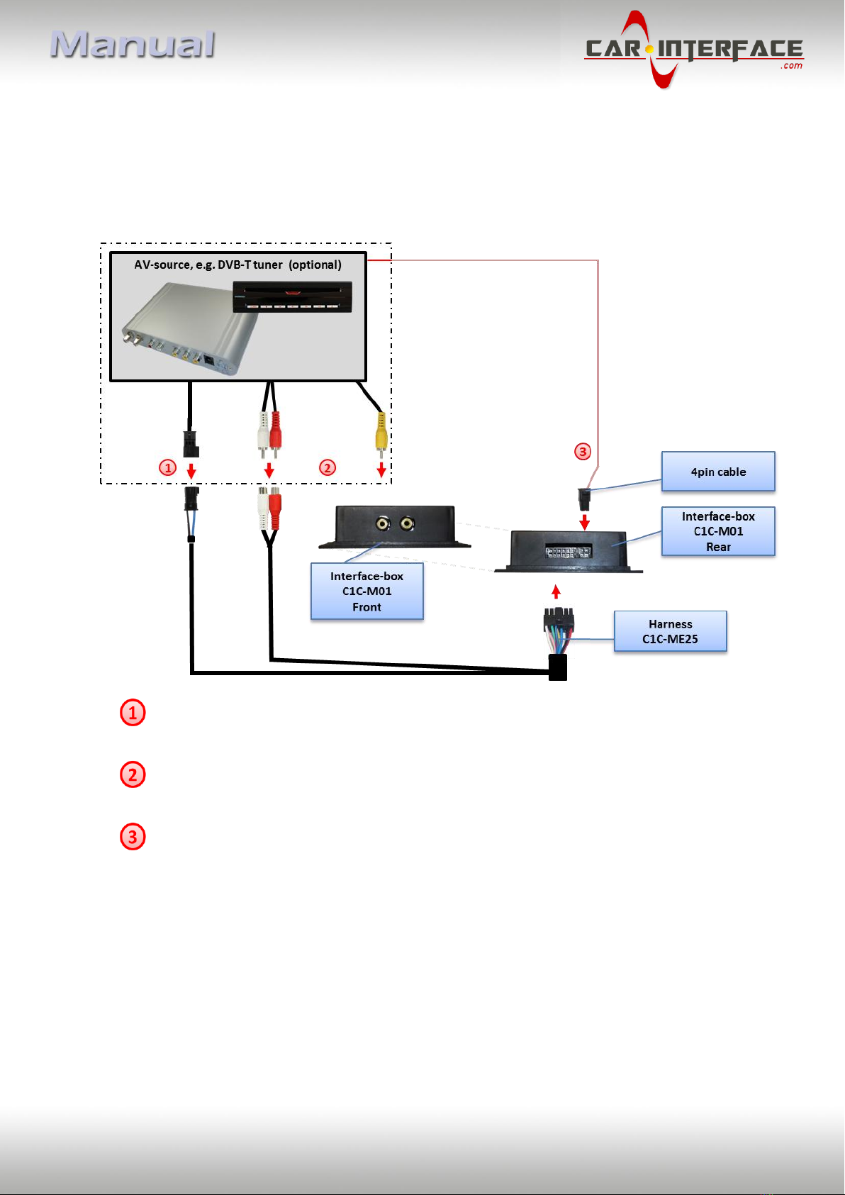
Using the respective STA-xxx IR-control cable, interconnect the blue female 3pin AMP
connector of harness C1C-ME25 and the IR-port of the AV-source.
Using an RCA-cable, interconnect the female RCA-port Video In of the Interface-box
C1C-M01 with the AV-output of the AV-source.
The pink ACC-output wire (+12V max. 1A) of the 4pin cable can be connected to the
ACC-input wires of the connected device to switch it on. It carries +12V when the
head-unit is running.
3.3.2. Installing AV-source’s IR-sensor additionally
Additionally to the control via OEM navigation, it is possible to install the original IR-sensor
of a connected device. By using the respective Y-adapter (e.g. STA-Y35MM or STA-RJ12) for
the IR-Port of the connected device, the controls of navigation AND device’s IR-sensor can be
connected and used simultaneously. Installation of the IR-sensor is recommended as the
controls via navigation are limited, and not all functions may be covered.

Version 20.09.2017 CI-C1-C25
Page8
3.3.3. After-market rear-view camera
Connect the video RCA of the after-market rear-view camera to female
RCA connector R-CAM IN of Interface-box C1C-M01.
Connect the green wire of the 4pin cable to the camera power supply (+12V max. 1A)
of the after-market rear-view camera and the grey wire to ground of the vehicle. The
green wire is high (+12V max. 1A) when reverse gear is engaged. The white wire is
not connected and has to be isolated. In some cases it is possible that the automatic
switching does not work. In this case connect the white wire to the reverse gear light
(+12V).
Note: Automatic switching to camera only works from c.LOGiC mode.
4. Operation
4.1. Activation of the video-in-motion function
The video of the c.LOGiC is displayed also in motion.
Note: On vehicles with previously installed factory TV-tuner an extra video-in-motion
interface might be necessary. It is not possible to determine this prior to testing.
4.2. Selecting the c.LOGiC as current AV-source
Push TV button of Comand to choose the c.LOGiC as current AV-source.

Version 20.09.2017 CI-C1-C25
Page9
4.3. Assigning device control
After selecting the c.LOGiC as current AV source, longpress
the number “1”-button or shortpress the “RET”-button.
The display in the instruments will show “TV 1” and
“RC01”. Turn right knob until the device-related IR-code as
described in device control table (appendix A) is reached.
Push right knob to confirm the assignment.
If the vehicle has no MFD display in the instrument panel, you must count the notches when
turning the knob (to the right +1, to the left -1). At the same time, remember that the
starting point is channel RC01 (the first notch to the right is then already RC02).
4.4. Button assignment table
The button assignment table shows which functions of the connected devices can be
executed by Comand buttons. Once the AV-input is activated, the Comand button in the left
column will execute the function described in the corresponding device column. The
function description equals the remote control buttons of the optional c.LOGiC remote
control or the additional device. On the additional device the writing may vary (e.g. AV
instead of Source).

Version 20.09.2017 CI-C1-C25
Page10
Additionally to the head-unit buttons, the steering-wheel buttons UP and DOWN can be
used for remote functions. DOWN-button has the same function as 17 on the head-unit and
UP-button has the same function as 18 on the head-unit.
4.5. Picture settings
To enter the picture settings menu longpress button 13.
The picture settings menu always starts with the
brightness settings. The respective current picture
value is displayed on the instrument panel.
Press the right knob to change from brightness to
colour and contrast (after contrast, the interface
starts again with brightness).
Turn the right knob to change the current picture
value. To quit the settings menu press button 13.
Button assignment table c.LOGiC Comand 2.5
COMAND
button
DVB-T
USB-LiNK
DVD-player
DVD-
changer
iPod®-control
Analog-tuner
1
SCAN
POWER
PLAY
PLAY
PLAY/PAUSE
SCAN
2
↑
↑
↑
↑
↑
VOL +
3
EPG
EXIT
STOP
STOP
POWER
FM
4
←
←
←
←
←
CH -
4 long
DISPLAY
VOL-
DISPLAY
DISPLAY
DISPLAY
5
OK
OK / PLAY
OK
OK
ENTER
MODE
6
→
→
→
→
→
CH +
6 long
AUDIO
VOL+
AUDIO
AUDIO
MUTE
FM
7
EXIT
MEDIA
PBC
DISC
SHUFFLE
MUTE
7 long
LANG
OSD
SUB
SUB
MUTE
8
↓
↓
↓
↓
↓
VOL -
9
MENU
SETUP
SETUP
SETUP
LIGHT
ADJUST
11
AV
MEDIA
AV
AV
EJECT
DISPLAY
11 long
POWER
POWER
POWER
POWER
POWER
POWER
14
↓
↓
TRACK +
TRACK +
TRACK +
CH +
15
↑
↑
TRACK -
TRACK -
TRACK -
CH -
16
OK
OK / PLAY
OK
OK
ENTER
MODE
17
CH -
TRACK -
TRACK -
TRACK -
TRACK -
CH -
18
CH +
TRACK +
TRACK +
TRACK +
TRACK +
CH +

Version 20.09.2017 CI-C1-C25
Page11
4.6. Audio settings
To enter the Comand’s audio settings menu press button 12.
5. Specifications
Operation voltage 10.5 –14.8V DC
Stand-by power drain <1mA
Operation power drain 240mA
Power consumption 3W
Temperature range -30°C to +80°C
Weight 95g
Measurements (box only) B x H x T 106 x 30 x 71 mm
Legal disclaimer: Mentioned company and trademarks, as well as product names/codes are registered
trademarks ® of their corresponding legal owners.
This manual suits for next models
1
Table of contents
Other Car-Interface.com Automobile Accessories manuals

Car-Interface.com
Car-Interface.com v.LOGiC CI-V5-MMI3G-PNP User manual

Car-Interface.com
Car-Interface.com CI-CARPLAY-SMEG-CI User manual

Car-Interface.com
Car-Interface.com CI-RL3-NBT2 User manual

Car-Interface.com
Car-Interface.com CI-RL4-NG4-HU User manual

Car-Interface.com
Car-Interface.com r.LINK CI-RL3-UCON8-LV User manual

Car-Interface.com
Car-Interface.com CI-RL-LR12-TF User manual

Car-Interface.com
Car-Interface.com CI-C1-C20 User manual

Car-Interface.com
Car-Interface.com r.LiNK User manual