3
ASSEMBLY OF PLANER TO BASE
Your 15” planer comes in 2 packing boxes, one contains
the assembled planer, the other, the assembled base,
in eed and out eed rollers plus dust chute.
The best way to li t the planer onto the base, is raising
the cutterhead, by turning the handwheel clockwise, Fig.
1(A) and placing 2 x 100 x 50mm boards on edge
onto the table to the le t and right o the machine. Then
lower the cutterhead till it grips the boards preventing
them rom slipping sideways. The protruding ends
become handles. You will require 1 it, healthy person
on each corner to li t the planer onto the base.
Align the 4 bolt holes at the corners, Fig. 1 (C) and with
the ront cover removed rom the base, insert bolts rom
underneath with the heads acing down, through both
the base and the planer, it nuts and washers provided
and tighten securely. Replace ront cover o base
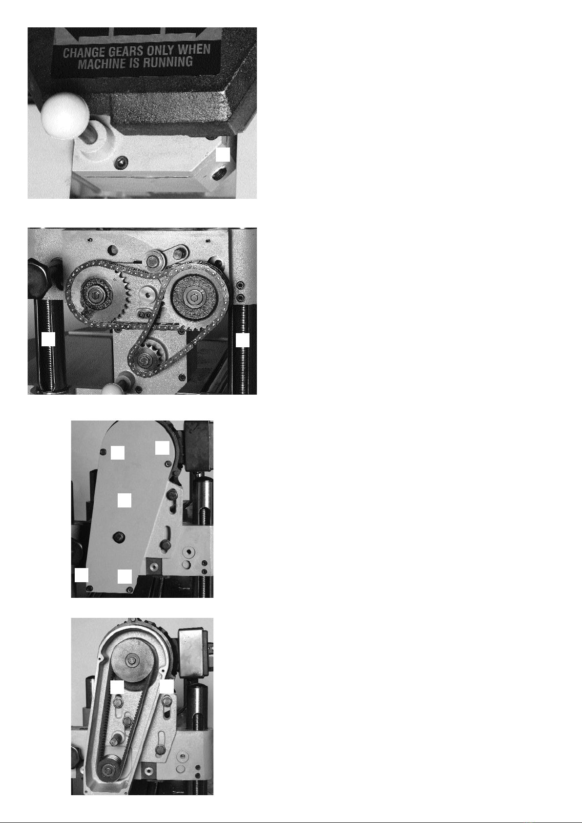
ASSEMBLING TOP COVER AND DUST CHUTE.
Fasten top cover at 4 corners with screws provided, Fig. 2 (A).
The dust chute ramp must point to the back o the plan-
er.Place dust chute over the ramp o the top cover and tighten
the 3 hex head bolts on the top Fig. 2 (B) and 3 allen key
bolts underneath. Fig. 2 (C)
DUST EXTRACTION CHUTE
This machine is designed to be used with a dust extractor,
having a minimum o 600c m. I using the machine without a
dust extractor, the dust chust should be removed to prevent
clogging o the 100mm outlet. When the dust chute is
removed, the rotating cutterhead is easily accessible and pre-
cautions, such as a guard should be installed to prevent acci-
dental hand contact.
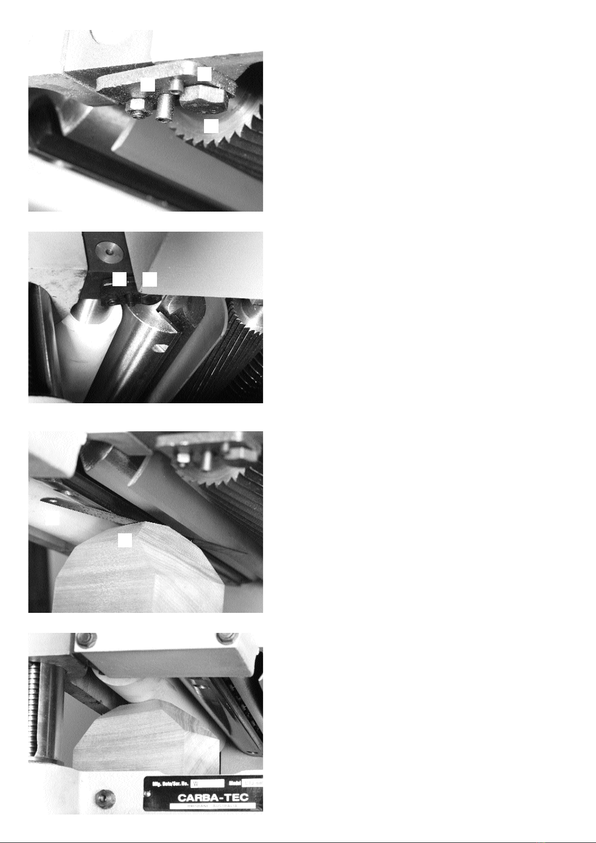
ANTIKICKBACK FINGERS (Fig. 3)
These ingers are designed to to prevent timber rom
being thrown back at the operator. No setting up is
required, however it is advisable to clean them occa-
sionally to prevent a build up o resin. Remember to dis-
connect machine rom power source be ore carrying out
any maintenance work.
A
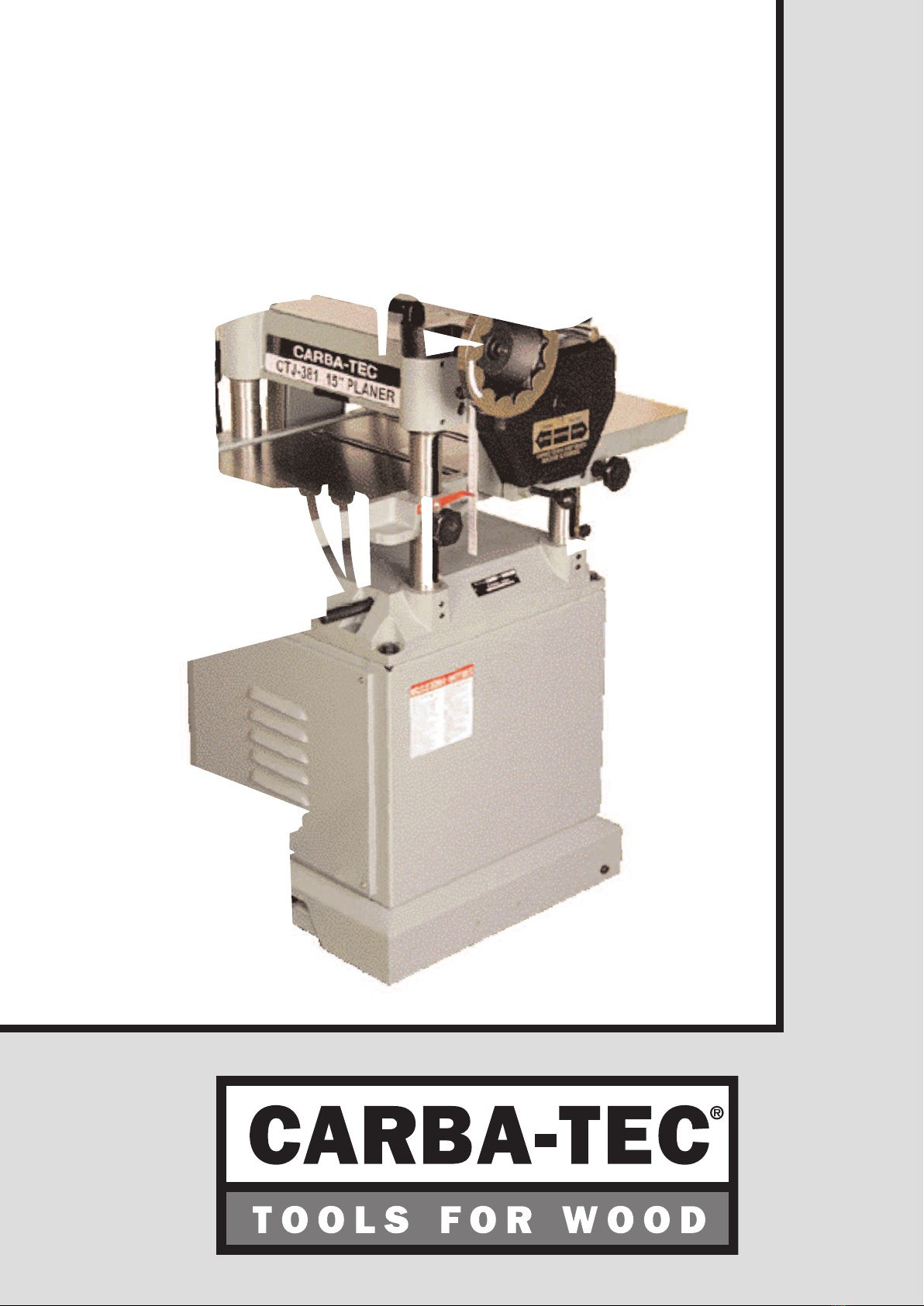
DEPTH OF CUT ADJUSTMENT
To adjust the depth o cut you need to raise or lower the head
assembly which contains the cutterhead. Loosen the locking
knobs, Fig. 1 (B) and turn the handwheel clockwise to raise
the cutterhead and anticlockwise to lower it. When you have
set the machine to the required depth o cut, tighten the lock-
ing knobs .The gauge Fig. 1 (D) will tell you what inished size
that setting will give you.
The maximum depth o cut is 3/16” on stock narrower than
6”. A limiter Fig. 4 (A) is positioned to allow no more than
1/8” to be taken o a board wider than 6”.
NOTE: Do not attempt to machine timber less than 6mm
thick as the material may shatter.
Fig. 1
Fig. 2
Fig. 3
Fig. 4
A
A
B
BBB
C
C
C
D