Carbide 3D Shapeoko HDM User manual

Shapeoko
GETTING STARTED GUIDE
HDM


1
support@carbide3d.com
12/18/2021 v1.0
Table of Contents
Welcome and Congratulations .............................................................................................2
Parts of the Shapeoko HDM .................................................................................................3
Important Safety Instructions...............................................................................................5
Step 1: Unpack the Machine.................................................................................................7
Step 2: Install the Software ..................................................................................................9
Step 3: Install the BitSetter HDM .......................................................................................10
Step 4: Set Up the Chiller....................................................................................................11
Step 5: Set Up the Spindle ..................................................................................................12
Step 6: Set Up the Electronics ............................................................................................13
Step 7: Enable & Configure the BitSetter HDM .................................................................14
Step 8: Control the Shapeoko HDM ...................................................................................16
Shapeoko HDM Maintenance.............................................................................................18
Tramming the HDM ............................................................................................................21
Extras ...................................................................................................................................24
12/18/2021 Version 1.0

2
docs.carbide3d.com
Welcome and Congratulations
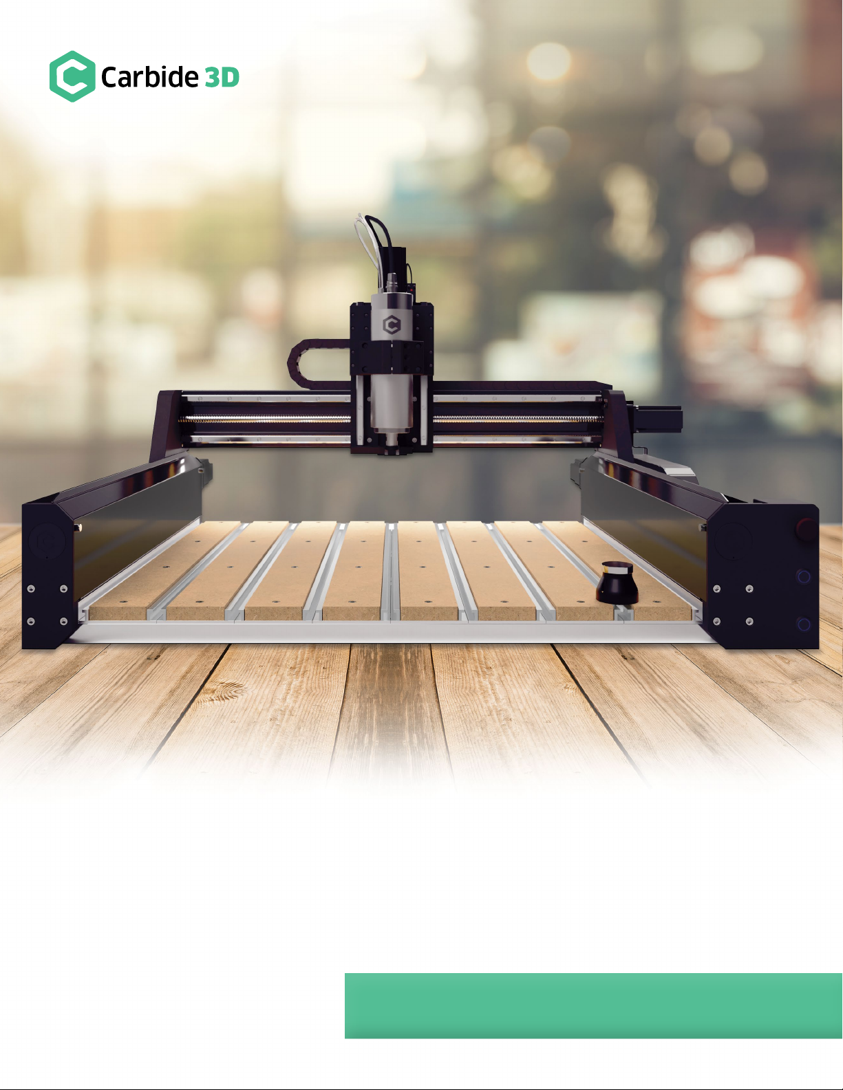
The Shapeoko HDM is a high-end, professional-graded CNC, the result of two years of prototyping and testing.
It cuts wood and non-ferrous metals (aluminum and brass) with ease and accuracy and will run all day long
without breaking a sweat. The machine comes fully-assembled, with the wiring already installed in the drag
chains and plugged into the Warthog controller. The Shapeoko HDM features:
•80mm water-cooled spindle (110 V or 220 V) with VFD control and chiller.
•Carbide 3D Warthog electronics.
•Hybrid Table with T-slot workholding.
•HG-15 linear bearings on every axis.
•Heavy-duty custom extrusions.
•16mm ballscrews on every axis with custom ballscrew wipers on X and Y-axis.
•Optical isolation and RS-422 serial connection for reduced electrical noise and static discharge.
In this guide we’ll walk you through everything you need to know to get started using your Shapeoko HDM. If you
encounter any issues setting up your machine, contact our tech support team at support@carbide3d.com and
we’ll get you up and running.
Do Not Connect to Ethernet-Enabled Devices
While an RS-422 Ethernet cable is used to connect the electronics cabinet to the computer adapter, the
Shapeoko HDM is NOT an Ethernet device. Do not use the RS-422 Ethernet cable to connect the electronics
cabinet or computer adapter to any Ethernet-enabled device, such as a modem or internet router.
Software Requirements
Carbide Motion version 5 or higher required for the Warthog controller.
Warranty
The Shapeoko HDM is covered by our standard Shapeoko warranty. Visit carbide3d.com/policy/warranty for
details.
Important Call-Outs
Throughout the guide, you will find information that we’ve called out for you to pay particular attention to. We
use three types of call-outs: Warnings, Notes, and Pro Tips.
Join the Carbide 3D Community
Join the Carbide 3D Community. Find or start a discussion on topics such as machine troubleshooting, product
announcements, software issues (Carbide Create, Carbide Motion, MeshCAM, Carbide Copper, Fusion 360),
problems with tutorials, community contests, project galleries, and more.

3
support@carbide3d.com
12/18/2021 v1.0
Parts of the Shapeoko HDM
Feed Hold Button
Machine Power Button
Spindle Lock-Out Button
Ballscrews (4): Z, X, YL, YR
Hybrid
Table
Y-Axis Side
Covers (2)
Machine-Control Buttons (3)
Spindle
Drag Chain Support Panels (2)
BitSetter
HDM
Stepper Motors (4): Z, X, YL, YR
Spindle Mount
Linear Rails (2 per Axis)
Drag Chains (2): X and Y
Coolant Tubes (2)
Front-Right Endplate

4
docs.carbide3d.com
Variable Frequency Drive (VFD)
Fans (2)
Warthog Controller
Electronics Cabinet —Inside
36V Power Supply
Latches (2)
Variable Frequency Drive (VFD)
Power Switch
Power Cord Jack
Cable Channels (3)
Electronics Cabinet —Outside

5
support@carbide3d.com
12/18/2021 v1.0
Important Safety Instructions
The Shapeoko HDM is a machine tool and requires the same caution that should be exercised with any power
tool. Please keep this manual in a safe place for reference.
WARNING: To reduce risk of burns, fire, electric shock, injury, and death, or damage to equipment or
property, read the following warnings carefully.
Eye Protection
Always wear safety glasses or goggles which are suitably impact-resistant.
Hearing Protection
Always wear earplugs or ear muffs. For long jobs, it may be desirable to wear both. Hearing damage is
cumulative and irreversible, so one should always err on the side of caution.
Respiratory Protection
Always wear a filter or respiratory mask suitable for the type of dust generated by the material being cut. If
necessary, arrange for dust collection and proper ventilation.
Clothing, Hair, and Jewelry
Always ensure that clothing, hair, and jewelry cannot become caught in the machine. Always wear appropriate
clothing; long-sleeved shirts, pants, and suitable footwear are recommended. When metal-working, gloves and
an apron are also recommended.
Machine Safety
Never reach into the machine’s working envelope while it is running. Always engage the spindle lock-out before
performing toolchanges. Always disable power to the machine and turn on the spindle lock-out (disable the
spindle) before adjusting the machine or performing maintenance. Never leave the machine running
unattended. Never move the machine during operation. Always inform someone before operating the machine
and check in with them after successfully completing work. Never allow children to use the machine
unsupervised.
Operating the Chiller
The chiller must be turned on when operating the spindle. Operating the spindle without the chiller could cause
fire and/or catastrophic damage to the spindle, VFD, or machine. Always leave the chiller on for an additional
5–10 minutes after turning off the spindle to allow the it to completely cool. Never run the chiller when the
coolant tank is empty. Ensure there is plenty of clear space on all sides of the chiller to allow for adequate air
circulation.

6
docs.carbide3d.com
Shut Off Machine When Not in Use
Always power down the machine after each use: enable the spindle lock-out, disable the power to the machine,
then turn off the power switch on the electronics cabinet. Wait 5–10 minutes, then shut off the chiller.
Fire Prevention
Never run the spindle with the chiller turned off. Consider the possibility of a fire caused by friction from the
spindle and take suitable fire prevention precautions (e.g. having a fire extinguisher handy and other suitable
precautions).
Power Requirements
A 20A circuit is recommended to run the HDM. Two separate outlets are required: one for the electronics
cabinet and one for the chiller.
End Mill Safety
Use care when handling end mills—both to avoid being cut and to avoid damaging them. Handling end mills with
suitable gloves, or using a cloth to avoid contaminating them, is recommended. Inspect end mills carefully before
each use, and ensure that they are securely held by the collet.
Debris Disposal
Recycle or safely dispose of milling debris and dust, keeping in mind flammability, (potential) spontaneous
combustion, and chemical considerations. Even natural materials can have disposal implications. For example,
walnut wood dust is allelopathic (it inhibits plant growth), an irritant to the skin and respiratory tract, and
potentially poisonous to some animals. All of these possible disposal implications are in addition to the
spontaneous combustion hazard posed by all types of sawdust.

7
support@carbide3d.com
12/18/2021 v1.0
Step 1: Unpack the Machine
WARNINGS:
•Use caution when lifting the machine; it
weighs over 240 lbs.
•Do NOT move the machine by lifting from the
ballscrews, linear rails, or drag chains.
LIFTING RECOMMENDATIONS:
•Remove the outer Hybrid Table slats and
extrusions before moving.
•Lift from the front edge of the X-extrusion and
the front end of the two Y-extrusions. See
Fig. 1.
Unbox the Shapeoko HDM
To remove the machine from the packing crate:
1. Lift the sides of the packing crate to remove
them.
2. Remove the two outer MDF slats and aluminum
extrusions from the Hybrid Table.
a. Remove the twenty-four (24) M6
screws (4 per MDF slat and 8 per
aluminum extrusion).
3. Use a #2 Phillips-head screwdriver to remove
the two (2) screws securing the machine to the pallet. Screw location is marked by red arrows in Fig. 2.
4. With the help of another person (or two), lift the machine from the pallet.
a. Lift from the front edge of the X-extrusion and the front end of the two Y-extrusions. See Fig. 1.
b. Try to keep the machine level when lifting.
5. Set the machine on a sturdy, level worksurface.
6. Re-install the two outer aluminum extrusions and MDF slats.
Figure 1
Figure 2

8
docs.carbide3d.com
Unpack the Accessory Boxes
Chiller Box
Item
Description
Qty
A
CW-3000 Chiller
1
B
Power Cord
1
C
User Manual
1
Accessories Box
Item
Description
Qty
D
Electronics Cabinet Power Cord
1
E
USB C-to-A Cable
1
F
Sweepy 80mm V2 Dust Boot with Hose Adapters (3)
1
G
#201 ¼” Square End Mill
1
H
Precision Collets: ¼” and 1/8” (ER-20)
2
I
Injection-Molded Clamping Kit: T-Nuts (12), M6×25mm (6) SHCS, Clamps (6)
1
J
Spindle Wrenches: 30mm and 22mm
2
K
Tool Kit: 1.5, 2, 2.5, 3, 4, 5mm Ball-Nose Hex Keys; 8, 10, 13mm Wrenches
1
Electronics Cabinet
Item
Description
Qty
L
Electronics Cabinet –Pre-Wired
1
M
Warthog Computer Adapter (Inside the Electronics Cabinet)
1
BitSetter HDM Box
Item
Description
Qty
O
BitSetter HDM
1
NOTE:
•If any items are missing or damaged in shipping, contact us at support@carbide3d.com and we’ll ship
you a replacement ASAP.

9
support@carbide3d.com
12/18/2021 v1.0
Step 2: Install the Software
Carbide Motion
Carbide Motion is the machine-control software for the Shapeoko HDM CNC machine. Carbide Motion lets you
control your machine by jogging it around, setting zeroes, and loading and running G-code. You’ll need to install
this software in order to operate the machine. Download and install the latest version of Carbide Motion:
1. Download Carbide Motion: carbide3d.com/carbidemotion/download (Windows and Mac OS X available).
2. Once the download completes, double-click the file and follow the instructions to install the software to
your computer.
3. After Carbide Motion installs, it is a good idea to drag the icon onto your Windows Taskbar (or Dock on a
Mac) for easy access to the program.
Check out the Carbide Motion User Guide: docs.carbide3d.com/assembly/carbidemotion/userguide.
Carbide Create
Carbide Create is a cross-platform 2D CAD/CAM software package made by Carbide 3D. This software is ideal for
designing 2D and 2.5D parts, has built in 3D previews and works flawlessly with your machine. You’ll use Carbide
Create to create 2D and 2.5D designs, generate toolpaths, and export G-code which you will run in Carbide
Motion to machine the part. Download and install the latest version of Carbide Create:
1. Download Carbide Create: carbide3d.com/carbidecreate/download (Windows and Mac OS X available).
2. Once the download completes, double-click the file and follow the instructions to install the software.
3. After Carbide Create installs, drag the icon onto your Windows Taskbar (or Dock on a Mac).
Check out the Carbide Create Video Tutorial Series: docs.carbide3d.com/assembly/carbidecreate/video-tutorials.

10
docs.carbide3d.com
Step 3: Install the BitSetter HDM
The BitSetter HDM is an automatic tool offset probe. It tracks the length of every tool installed in the spindle and
updates the Z-zero position based on changes to the length of the tool. The BitSetter HDM will automatically
measure the tool length in three circumstances:
•When you press the Initialize button in Carbide Motion.
•When you press the Load New Tool button in Carbide Motion.
•When your G-code program requests a toolchange (Carbide Motion will prompt you to change the tool).
If you change the tool any other time, the BitSetter HDM will not re-measure the tool length, so it will not update
the Z-height.
IMPORTANT NOTES ABOUT CHANGING TOOLS:
•When running a job, do NOT perform toolchanges without first being prompted by Carbide Motion.
•When no project is in progress, ALWAYS press the Load New Tool button in Carbide Motion and
follow all onscreen prompts to change the tool.
•If you accidentally change the tool unprompted, click the Load New Tool button to tell the BitSetter
to measure the tool length, then go check or reset your Z-zero value.
Installing the BitSetter HDM
The BitSetter HDM is designed to be installed almost anywhere on the Hybrid Table, but we recommend
installing it the far-right T-track slot. The BitSetter HDM is anchored to the Hybrid Table via a T-nut and M6
screw.
1. Remove the three (3) M3 screws from the BitSetter HDM body, and then remove the body from the thin
baseplate.
2. Loosen, but do not remove, the M6 screw in the center of the baseplate.
3. Slide the T-nut into the desired T-track slot in the Hybrid Table.
4. Tighten the M6 screw to secure the baseplate.
5. Re-insert and fully tighten the M3 screws secure the BitSetter HDM to its baseplate.
6. Locate the 3-pin BitSetter cable exiting the rear cable channel of the electronics cabinet.
7. Plug the cable into the 3-pin pigtail exiting the base of the BitSetter HDM.
8. Route the BitSetter cable down the slot in the Hybrid Table and out the back of the machine.
NOTE: Instructions for enabling the BitSetter HDM in Carbide Motion are located in Step 7 on page 14.

11
support@carbide3d.com
12/18/2021 v1.0
Step 4: Set Up the Chiller
Chiller Overview
The CW-3000 chiller is a non-refrigerated, industrial chiller. It continually routes coolant (distilled water,
windshield wiper fluid, or antifreeze) through the spindle to prevent overheating and to maintain consistent,
high-quality cutting.
In the event of a malfunction, the chiller will display an error code on the LED screen. Error codes are listed in
the included chiller manual. Contact the Carbide 3D tech support team at support@carbide3d.com for
assistance troubleshooting error codes.
WARNINGS:
•The chiller MUST be turned on when operating the spindle. Operating the spindle without the chiller
could cause fire and/or catastrophic damage to the spindle, VFD, or machine.
•Always leave the chiller on for an additional 5–10 minutes AFTER turning off the spindle/VFD to allow
the spindle to completely cool.
•Never run the chiller when the coolant tank is empty.
•Ensure there is plenty of clear space on all sides of the chiller to allow for adequate air circulation.
NOTES:
•Always use distilled water, windshield wiper fluid, or antifreeze in the chiller. Using tap or other non-
distilled water will lead to bacteria growth inside the tank.
•Antifreeze is recommended when operating in a cold environment.
Setting Up the Chiller
1. Place the chiller on the base of the workbench or on the floor beneath it.
a. Each side of the chiller must be clear so air can circulate freely around the device. This will keep
the coolant at ambient air temperature.
2. Open the water-supply inlet on the top of the chiller and fill the reservoir tank with distilled water,
windshield wiper fluid, or antifreeze. Do not overfill.
3. Locate the two 8mm clear coolant tubes exiting the Y-Axis drag chain (at back-right corner).
4. Push the tubes into the two 8mm push-fittings on the back of the chiller. The tubes are interchangeable.
5. Plug the power cord into the jack on the back of the chiller and into a power outlet.

12
docs.carbide3d.com
Step 5: Set Up the Spindle
The 80mm spindle has an 8–24k RPM water-cooled motor. The spindle is controlled by the variable-frequency
drive (VFD) and cooled by the closed-loop chiller. The VFD’s custom-interface board turns the spindle on and off
and sets the RPM based on the project G-code.
The display screen on the VFD will show the spindle RPM during operation and error codes in the event of a
malfunction. Contact the Carbide 3D tech support team at support@carbide3d.com for assistance
troubleshooting error codes. Download the VFD manual for error code and safety information:
docs.carbide3d.com/assembly/HDM/VFDmanual.pdf.
WARNINGS:
•The chiller MUST be turned on when operating the spindle. Operating the spindle without the chiller
could cause fire and/or catastrophic damage to the spindle, VFD, or machine.
•Always engage the spindle lock-out before performing toolchanges.
•Do not attempt to operate the VFD via its control panel; Carbide Motion and the G-code control the
spindle via the VFD.
Adjusting the Height of the Spindle (Optional)
To move the spindle up or down in the spindle mount:
1. Loosen the top and bottom M6×30mm screws on the right side of spindle mount.
2. Insert an M6 screw in the middle hole in the mount and slowly tighten.
a. Tighten until the mount opening is just wide enough to slide the spindle up or down.
Once the spindle is at the desired height:
1. Remove the M6 screw from the middle hole.
2. Fully tighten the top and bottom M6×30mm screws to secure the spindle.

13
support@carbide3d.com
12/18/2021 v1.0
Step 6: Set Up the Electronics
The electronics cabinet contains the Warthog controller, power supply, and variable-frequency drive (VFD),
which controls the water-cooled spindle. The Warthog controller uses the 36-volt power supply to power the
motors and gantry. Warthog uses a combination of optical isolation and an RS-422 serial connection to the
computer for increased immunity from electrical noise and static discharge.
Included with the electronics cabinet is a separate Warthog Computer Adapter that will be the connection point
between the electronics cabinet and your machine-control computer. An RS-422 Ethernet cable is used to
connect the electronics cabinet to the Warthog Computer Adapter; however, the machine and its components
are not Ethernet devices.
WARNINGS:
•Always turn off the power switch on the electronics cabinet after using the machine.
•Before opening the electronics cabinet, always turn off the power switch AND unplug the power
cable from the outlet.
•Do not use the RS-422 Ethernet cable to connect the electronics cabinet or computer adapter to any
Ethernet-enabled device, such as a modem or internet router.
•Always ensure the two fans on the side of the electronics cabinet are completely clear to ensure they
receive plenty of airflow.
Connecting the Electronics Cabinet
1. Place the electronics cabinet on the base of the workbench or on the floor beneath it.
2. Locate the RS-422 Ethernet cable exiting the rear cable channel of the electronics cabinet.
3. Plug the RS-422 cable into the Ethernet port on the Warthog Computer Adapter.
4. Plug the USB C-to-A cable into the USB-C port on the computer adapter.
5. Place the computer adapter on top of the electronics cabinet lid or affix it to the side of the workbench.
6. Insert the power cable into the jack on the side of the electronics cabinet.
7. Plug the power cable into an outlet.

14
docs.carbide3d.com
Step 7: Enable & Configure the BitSetter HDM
Setting Up the BitSetter HDM
Home the Machine
First, connect to and home the machine:
1. Power up your computer.
2. Connect the USB cable to the computer.
3. Start Carbide Motion.
4. Turn on the electronics cabinet power switch.
5. Press the Machine Power button on the front-right endplate to enable power to the machine.
6. In Carbide Motion, click the Connect to Cutter button.
7. Click the Initialize Machine button.
PRO TIP:
The machine can be re-homed later on in a project (see Fig. 3). To do so:
1. Click MDI in the top menu bar.
2. Enter $H in the command line and click the Send button.
Figure 3

15
support@carbide3d.com
12/18/2021 v1.0
Position the Spindle
Position the spindle directly above the BitSetter HDM:
1. In Carbide Motion, click Jog in the menu bar at the top of the screen.
2. On the Jog screen, click the Set Zero button.
3. Click the Clear All Offsets button and then click Done.
4. Jog the machine so that the spindle is directly above the BitSetter HDM.
Enable the BitSetter HDM in Carbide Motion
Enable the BitSetter HDM and save the spindle position in the settings menu:
1. In Carbide Motion, click Settings in the menu bar.
2. Click the Options tab in the Settings menu.
3. In the BitSetter section, select the Enabled check box.
4. Click the Use Current Location button to save the current X/Y location of the spindle.
5. Click Ok to save and close.
Set the Post Processor in Carbide Create
In order for the BitSetter HDM to work, the post processor in Carbide Create must be correctly set:
1. In Carbide Create, go to Edit >Select Post Processor in the menu bar.
2. Select Carbide 3D Shapeoko.
3. In the Output Units dropdown list, select Metric or Inch.
4. Click Ok to save and close.

16
docs.carbide3d.com
Step 8: Control the Shapeoko HDM
Machine-Control Buttons
There are three machine-control buttons on the front-right endplate (see Fig. 4):
1. Feed Hold Button: Press and hold the button for
momentary feed hold. Release the button to return to
normal operation. When the button is pressed, Carbide
Motion will open a dialog box letting you know that feed
hold is activated. When the button is released, a dialog box
will open letting you that feed hold has been deactivated.
2. Machine Power Button: Press to enable/disable power to
the machine. When the blue LED is lit, power to the
machine is enabled.
3. Spindle Lock-Out Button: Press to enable/disable the
spindle lock-out. When the red LED is lit, the spindle is
enabled. When the button LED is off, spindle is disabled.
WARNINGS:
•Always turn off the power switch on the electronics
cabinet after using the machine.
•Before opening the electronics cabinet, always turn off the power switch and unplug the power cable
from the outlet.
IMPORTANT NOTES ABOUT CHANGING TOOLS:
•When running a project, do NOT perform toolchanges without first being prompted by Carbide
Motion.
•When no project is in progress, ALWAYS press the Load New Tool button in Carbide Motion and
follow all onscreen prompts to change the tool.
Controlling the Shapeoko HDM
To run a project:
1. Turn on the electronics cabinet power switch.
2. Press the Machine Power button to turn on the machine.
3. Connect to and home the machine.
1
2
3
Figure 4

17
support@carbide3d.com
12/18/2021 v1.0
4. Load the G-code and the first tool, and set job zero. Ensure the spindle lock-out is engaged (the button
LED will be off) before loading the first tool.
5. Turn on the chiller.
6. Press the Spindle Lock-Out button to enable the spindle (the red LED will turn on).
7. Start the project in Carbide Motion. Carbide Motion, via the VFD, will automatically turn the spindle
on/off and control the RPM.
8. When prompted by Carbide Motion to perform a toolchange:
a. Press the Spindle Lock-Out button to disable the spindle (the button LED will turn off).
b. Load the new tool.
c. Press the Spindle Lock-Out button again to enable the spindle (the red LED will turn on).
d. Press the Resume button in Carbide Motion. The BitSetter HDM will automatically measure the
length of the new tool and update the Z-height.
WARNING: Do NOT perform a toolchange without first being prompted by Carbide Motion. When you
change the tool unprompted, the machine does not know to measure the length of the new tool with the
BitSetter HDM and to re-zero your Z-Axis; this can result in the Z-Axis plunging too deeply into your stock.
9. Press and hold the Feed Hold button any time you wish to momentarily pause the feed. Release the
button to resume normal operation.
10. To pause the project and the machine during operation, press the Pause button in Carbide Motion. Press
the Start button to resume the project.
11. Once the project is complete, disable the spindle and disable the power to the machine. Then, turn off
the electronics cabinet power switch.
12. Leave the chiller on for an additional 5–10 minutes to allow the spindle to completely cool.

18
docs.carbide3d.com
Shapeoko HDM Maintenance
Recommended Oil
We only recommend using Mobile Vactra No 2 oil on linear rails, ball bearing carriages (AKA guides or carriages),
and ball screws. It should NOT be used on any other parts of the machine.
Follow the safety guidelines provided with the oil. Wear gloves and safety glasses.
Linear Rail and Ball Bearing Carriage Maintenance
Our linear rails and guides are rated for tens of thousands of hours of use. To keep them in optimal condition, we
recommend the following:
General Maintenance
•We recommend vacuuming or brushing out the Y-axes daily.
•After every use, wipe down the linear rails and guides with a clean, dry, lint-free cloth to remove any
dust or debris.
•We do not recommend using compressed air on the linear rails and guides.
•Never use water-based products on the linear rails and guides.
•Rub a small amount of the recommended oil on the linear rails using a lint-free cloth. Be sure to clean off
any excess.
Lubricating the Axes
Maintenance intervals will vary according to use, but we recommend every 3–6 months (or more frequently
depending on use) lubricating the linear rails, carriages and ball screws. Everything is rubber sealed with dust
wipers but additional oiling will keep the linear rails in top condition.
To lubricate an axis:
1. Remove the two Y-Axis inside covers.
2. Move the axis to be lubricated to one end of its travel, e.g. all the way to the top (Z-Axis), back (Y-Axis),
or left (X-Axis).
3. Fill a large-bore plastic syringe with Mobile Vactra No. 2 oil.
Table of contents
Other Carbide 3D Control System manuals
Popular Control System manuals by other brands

Sky Elevator
Sky Elevator Sky 301-VS Troubleshooting

Siemens
Siemens simatic c7-621 Hardware installation guide

Mazak
Mazak STX SC L PLUS CONTROL Training manual

Targetmax
Targetmax TA920 instruction manual

ECOFOREST
ECOFOREST ecoSMART Supervisor USER, INSTALLER AND TECHNICAL SERVICE MANUAL

Steridose
Steridose sterimixer Startup guide