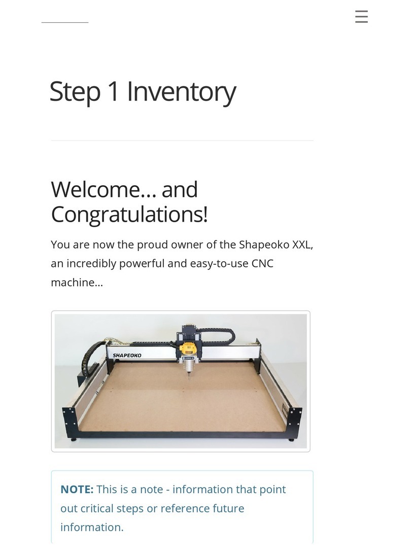
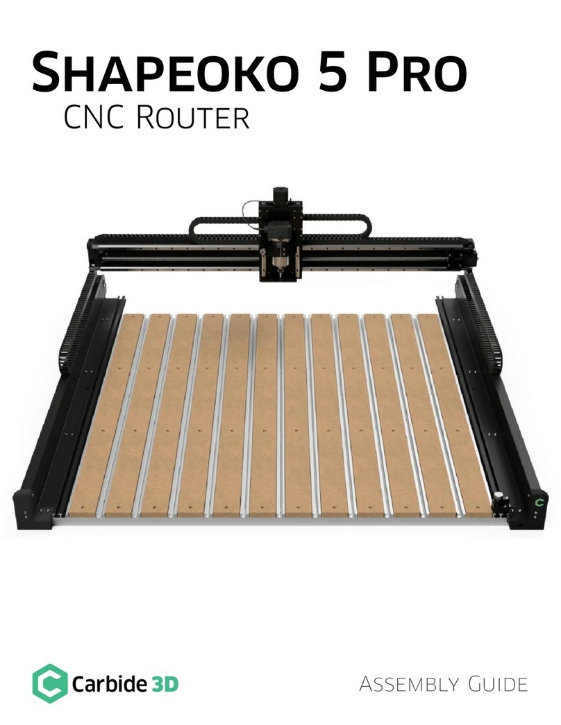
Carbide 3D Shapeoko XL User manual


Welcome and Congratulations
You are now the proud owner of the Shapeoko XL, an incredibly powerful and easy-to-use CNC machine.
In this guide we will walk you step-by-step through the assembly of your Shapeoko XL. If you run into any
problems along the way, send us an email at suppor[email protected] and we’ll help get you back on track!
Important Notes Used in This Guide
We use three types of call-outs: Warnings, Notes, and Pro Tips:
Do NOT Use Power Tools
Use hand tools only. Do NOT use power tools to assemble your Shapeoko XL.
Finger-Tight Only
to do so.
Firmware
Stepper Motors
cause them to generate electricity.
Have Questions? Need Help?
Table of Contents
Welcome and Congratulations....................................................................................................1
Important Safety Instructions.....................................................................................................2
Machine Operating Checklist.......................................................................................................3
Step 1 Inventory.............................................................................................................................4
Step 2 Baseframe.........................................................................................................................12
Step 3 Carriages............................................................................................................................16
Step 4 Gantry.................................................................................................................................24
Step 5 Belting................................................................................................................................28
Step 6 Drag Chain.........................................................................................................................34
Step 7 Proximity Switches.........................................................................................................42
Step 8 Wiring.................................................................................................................................46
Step 9 Cleanup..............................................................................................................................50
Step 10 Compact Router.............................................................................................................54
Step 11 Level and Square...........................................................................................................58
Next Steps......................................................................................................................................59
Connect to Power.........................................................................................................................60
Download the Software..............................................................................................................60
Congure Carbide Motion 5......................................................................................................61
Workholding............................................................................................................................63
Cutting Tutorials and Projects...................................................................................................64
User Guides and Video Tutorials...............................................................................................64
Glossary of Terms.........................................................................................................................65
WARNING: This is a warning. Information in these boxes is VERY important. Pay close attention.
WARNING: When moving the gantry by hand, go slowly. The power generated by the stepper motors
will feel like bumps. If the lights on the Carbide Motion board are lighting up, it’s very important to slow
down because you are pushing electricity back through the board. Too much back ow could damage
the Carbide Motion board.
NOTE: This is a note—information that points out critical steps or information for future reference.
PRO TIP: This is a pro tip. Anytime you see one of these, you will nd helpful additional information.

2docs.carbide3d.com [email protected] 3
Important Safety Instructions
The Shapeoko is a machine tool and requires the same caution that should be exercised with any power
tool.
Eye Protection
Always wear safety glasses or goggles which are suitably impact resistant.
Hearing Protection
Always wear ear plugs or ear muffs. For long jobs, it may be desirable to wear both. Hearing damage is
Respiratory Protection
Clothing, Hair, and Jewelry
Always ensure that clothing, hair, and jewelry cannot become caught in the machine. Always wear
Machine Safety
Always inform someone before operating the machine and check in with them after successfully completing
Fire Prevention
Outlet Requirements
Plug the router into an outlet that has a dedicated on/off switch. Be sure this is accessible while the machine
is running, in case you should need to shut off the Shapeoko XL immediately.
End Mill Safety
carefully before each use and ensure that they are securely held by the collet.
Debris Disposal
tract, and potentially poisonous to some animals. All of these possible disposal implications are in addition to
the spontaneous combustion hazard posed by all types of sawdust.
Machine Operating Checklist
1. Be Safe
glasses/goggles, hearing protection, and respiratory protection.
2. Check the Machine
Check that all bolts and set screws are tight, V-rails are in good condition with no nicks or other damage, belts are tight and
in good shape, wiring is in good condition with continuity and securely fastened, and that nothing is frayed or broken and
3. Secure the Workpiece
4. Mount the Router
5. Examine the End Mill
Examine each end mill prior to use to ensure that it is sharp, in good condition, and not chipped (this is best done with a loupe
as the deepest intended cutting depth. Check to make certain that the collet is tight and will not work loose during operation
6. Clear the Work Area
Ensure the work area is clear and all cables run without interference. Most importantly, check that there is nothing beneath
7. Connect to a Computer
To connect the Shapeoko XL to a computer:
a. Power up the computer.
b. Connect the USB cable to the port at the rear of the Carbide Motion board and to your computer.
c. Start Carbide Motion 5 on your computer.
d.
e.
f. If necessary, home the cutting tool to the proper place in relation to the workpiece.
8. Disconnect the Touch Probe
9. Double Check the Work Area
check.
10. Send NC File to Machine
correct speed. Follow all prompts for tool changes.
11. Monitor the Machine During Operation
While staying clear of the work area, monitor the machine during operation. Ensure there is no build-up of dust, debris, or
machine is operating.
12. Finish and Clean Up
such as isopropyl alcohol.

Step 1
Inventory
4docs.carbide3d.com [email protected] 5
Unbox the Shapeoko XL
Figure1‑2.
Item Description Qty Other Info
AShapeoko XL Assembly Guide 1 This Printed Assembly Guide
BY-Axis Left Assembly Box 1 Contains Y-Axis Left Carriage
CY-Axis Right Assembly Box 1 Contains Y-Axis Right Carriage
DXL Final Assembly Box 1 Contains Hardware and Components Needed for
Assembly
EX/Z+ Box 1 Contains the Z-Plus Carriage, Components, and
Hardware
FPre-Assembled XL Wiring Harness Box 1 Contains Wiring Harness, Kits, and Hardware
G 1
HCross Strap Package 1 23.5x 7x 1.5Package Contains 3 Identical
Cross Straps
IAluminum Extrusion Rails Package 1 40x 7.5x 3.5Package Contains 3 Unique
Extrusion Rails
JEndplate Package 1
Endplates
K 141x 0.75
Optional Items
LCarbide Compact Router Box 1 Contains the Compact Router and Accessories/Tools
Take Inventory
damage and quantity, then carefully set each aside until they are needed for assembly.
PRO TIP: Your Shapeoko XL kit has been carefully packaged by hand and double checked for accuracy. If,
after completing your inventory, you nd that something is missing or damaged, contact us at
Figure1-2

6docs.carbide3d.com [email protected] 7
Y‑Axis Left Assembly &
Y‑Axis Right Assembly Boxes
match the carriages shown in Figure1‑3. The
Right and Left Assembly are mirror images.
XL Final Assembly Box
bags, and smaller bags may be packed into larger bags This box contains the items listed in the table on the
next page and shown in Figure1‑4.
XL Final Assembly box contents; see Figure1‑4:
Item Description Qty
A
B 4
CRouter Mount 1
DRouter Mount Adapter Ring 1
E
4
F 1
GExtrusion Rail Hardware: M6 x 12mm Button Head Cap Screws 24
H 12
IToothed Belt 3
J
3
K 1
LPower Cord 1
MPower Supply 1
NUSB Cable 1
OLarge Zip Tie 2
PPermanent Marker 1
Q#201 ¼-inch Square End Mill Cutter 1
R
need to adjust the motor pulley set screws.
NOTE: Save both Y-Axis Assembly boxes and
the foam packing blocks inside. They’ll be used
to support the gantry during assembly.
Figure1-4
Figure1-3

docs.carbide3d.com [email protected] 9
X/Z+ Box
This box should contain all the items listed in the
table below and shown in Figure1‑5.
Item Description Qty
AZ-Plus Carriage with Z-Axis Stepper Motor and Z-Axis Proximity Switch 1
BX-Axis Stepper Motor 1
CM5 x 10mm Socket Head Cap Screw 4
D 5
Pre‑Assembled XL Wiring
Harness Box
This box should contain all the items listed in the
table below and shown in Figure1‑6.
Item Description Qty
A 1
B
29
C
12
D 35
E 1
Sweepy Box
Figure1‑7.
Cross Straps
Figure1‑8
properly formed and that it is seated squarely in
place.
Aluminum Extrusion Rails
Examine the three rails, shown in Figure1‑9, and
identify the following:
• X-Axis Rail (X-Rail): has Shapeoko/warning
threaded screw holes along the back.
• Y-Axis Left Rail (Y1-Rail):
side.
• Y-Axis Right Rail (Y2-Rail):
threaded screw holes along one side.
Figure1-7
Figure1-8
Figure1-9
Figure1-5
Figure1-6

10 docs.carbide3d.com [email protected] 11
Endplates
Figure1‑10.
formed and that it is seated squarely in place.
MDF Baseplate
in Figure1‑11.
Carbide Compact Router
Box
Optional Equipment. If you ordered the Carbide
Figure1‑12.
Additional Required Tools
The following tools are not included in your
Shapeoko kit, but are required for assembly. See
Figure1‑13:
Item Description Qty
AFlush Cut Pliers or Scissors 1
B 1
CRuler 1
Recommended Tools
The following tools are recommended for assembly,
but not included. See Figure1‑13:
Item Description Qty
D
Wrench 2
E
Easy-Peel Masking Tape (e.g.
blue painter’s tape; nothing that
1
FFlashlight 1
GTape Measure 1
Before You Begin Assembly
This guide contains many instructions with a
directional reference, such as: left, right, front,
back, rear, inside, outside, etc.
standing in front of, and looking at, the machine as
shown in Figure1‑14
of the machine.
familiarize yourself with the machine’s directional
and down. See Figure1‑15.
WARNING: MDF is sensitive to moisture.
Avoid liquids and/or high humidity. If you are
in a high-humidity environment, consider
sealing the MDF baseplate with a suitable
nish, such as spar urethane or lacquer.
Figure1-10
Figure1-11
Figure1-12
Figure1-13
Figure1-14
Figure1-15

Step 2
Baseframe
12 docs.carbide3d.com [email protected] 13
Required Components
See Figure2‑2:
Item Description Location Qty
AEndplate N/A 2
B N/A 2
CCross Strap N/A 3
D XL Final Assembly Box 4
EM5 x 25mm Button Head Cap Screw XL Final Assembly Box 15
Required Tools
See Figure2‑3:
Item Description Qty
A3mm Hex Key 1
B 1
Recommended Tools
See Figure2‑3:
Item Description Qty
C 2 or 3
DFlashlight 1
ETape Measure 1
Position the Cross Straps
1.
apart. See Figure2‑4.
WARNING: Do not assemble the Shapeoko
on the oor; a large workbench is essential.
The completed dimensions of the Shapeoko
XL are 44.8″ (X) x 23.9″ (Y) x 18.5″ (Z).
Figure2-2
Figure2-3
Figure2-4

14 docs.carbide3d.com [email protected] 15
Attach the MDF Baseplate
1.
straps, with the countersunk holes facing up.
2.
baseplate across the middle. See Figure2‑5.
3. Turn the screws until they stop but do not fully
tighten.
Attach the Rear Endplate
1. UNDER all three cross
straps along the rear of the baseframe and
align the screw holes. See Figure2‑6.
2.
button head cap screws to secure the rear
endplate to the baseframe. See Figure2‑7.
3. Turn the screws until they stop but do not fully
tighten.
Attach the Front Endplate
1. Slide the remaining endplate UNDER all three
cross straps along the front of the baseframe
and align the screw holes.
2.
button head cap screws to secure the front
endplate to the baseframe. See Figure 2-8.
3. Turn the screws until they stop but do fully
tighten.
Attach the Adjustable
Leveling Feet
1. Lift/prop each corner of the baseframe and
Figure2‑9.
Level the Baseframe
Assembly
1.
diagonally. See Figure2‑10.
2.
measuring diagonally across the baseframe
from the outside edges of the endplates. Check
both sides. The machine is square when the
two measurements are equal. Approximates
are acceptable at this stage as the machine is
completed in Step 11: Level and Square.
NOTE: We’ll come back and tighten all of the
baseframe screws later on when squaring
the machine.
PRO TIP: Use a spare hex key or two to
align the middle three screw holes. See
Figure2‑5. To further help with hole
alignment, shine a ashlight under the
assembly to illuminate the holes from the
bottom. Adjust as necessary.
NOTE: If you are having trouble getting any
of the endplate screws to line up, try starting
from the center and alternating your way out
to the ends. Apply a little more downward
force, but be careful not to cross-thread.
Screws may t tightly but they should not
wobble when turned. Still having trouble?
Figure2-5
Figure2-6
Figure2-7
Figure2-9
Figure2-8
Figure2-10

16 docs.carbide3d.com [email protected] 17
Required Components
See Figure3‑2:
Item Description Location Qty
A X-Axis Aluminum Extrusion Rail (X-Rail) N/A 1
B N/A 1
C N/A 1
D Y-Axis Left Carriage (Y1-Carriage) Y-Axis Left Assembly Box 1
EM6 x 12mm Button Head Cap Screw XL Final Assembly Box 4
F Z-Plus Carriage (Z-Plus) X/Z+ Box 1
G X/Z+ Box 1
HM5 x 10mm Socket Head Cap Screw X/Z+ Box 4
ITramming Plate X/Z+ Box 1
J X/Z+ Box 4
KRouter Mount XL Final Assembly Box 1
LM5 x 16mm Button Head Cap Screw XL Final Assembly Box 2
MM5 x 55mm Socket Head Cap Screw XL Final Assembly Box 2
NRouter Mount Adapter Ring XL Final Assembly Box 1
OLoctite 242 Threadlocker XL Final Assembly Box 1
P Y-Axis Right Carriage (Y2-Carriage) Y-Axis Right Assembly Box 1
QM6 x 12mm Button Head Cap Screw XL Final Assembly Box 4
Required Tools
See Figure3‑3:
Item Description Qty
A3 and 4mm Hex Key 2
B10mm Wrench 1
Recommended Tools
See Figure3‑3:
Item Description Qty
C10mm Combination Wrench 1
DMasking Tape 1
Figure3-2
Figure3-3
Step 3
Carriages

docs.carbide3d.com [email protected] 19
Open the V‑Wheels
1. Figure3‑6:
a.
b.
c.
2.
eccentric nuts CLOCKWISE until the dimple is
facing UP. Refer back to Figure3‑4.
Assemble the Z‑Plus
Attach the X‑Motor
1. Familiarize yourself with the features and
layout of the Z-Plus. See Figure3‑7.
2.
30mm standoffs pointing up.
3.
spaced standoffs in the center of the Z-Plus,
Figure3‑8.
4.
socket head cap screws to secure the X-motor
to the Z-Plus.
ECCENTRIC NUTS AND V-WHEELS EXPLAINED
Eccentric nuts and V-wheels are what we use to adjust the gantry at the intersect between the carriage V-wheels
and the V-rails. A loose connection here is referred to as carriage slop. To eliminate slop, a very small amount of
tension is added between the wheels and rail. Too much tension and the wheels will deform, causing bumpy and
constrained motion. Not enough tension, and the carriages will wobble. When tension is just right, the carriages glide
smoothly and without slop for the highest-quality cuts.
Our HD eccentric nuts, in combination with the attached V-wheel, operate as a cam, converting the rotational motion
of turning the nut, into linear motion at the V-wheel. A dimple on one the side of the nut indicates the furthest point to
center of the offset threads. When the dimple is facing UP, the distance between the top and bottom wheel is at its
greatest and the V-wheels are OPEN. When the dimple is facing DOWN, the opposite is true, and they are CLOSED.
See Figures 3‑4 and 3‑5.
When adding tension to a loose V-wheel, turn the eccentrics clockwise. Turning counter-clockwise will loosen the
bolted connection between nut and wheel. If this happens, re-tighten with a 10mm wrench and a 3mm or 4mm hex
key.
Not much tension is needed for the carriages to be secure. The wheels should only be snug against the rail. Reach
under and spin the V-wheel with your nger. If it rotates freely, turn the eccentric nut clockwise until you feel some
friction against the rail and the carriage is free from slop.
Figure3-5
Figure3-4
Figure3-6
Figure3-8
Figure3-7

20 docs.carbide3d.com [email protected] 21
Identify the Front of the
Tramming Plate
feature of the Z-Plus made possible by the tramming
plate. Tramming before each new project sets the
router mount perfectly parallel to the X-Axis and
Three of the four M5 mounting holes on the plate are
enlarged by 0.75mm. The one standard-sized M5
UPPER-LEFT
corner when the plate is mounted to the Z-Plus. This
is considered the FRONT of the tramming plate.
1. Figure3‑9.
2. Inspect the top two screw holes to determine which of the two is the smaller.
3. Position the tramming plate with the smaller hole at TOP-LEFT. This is the FRONT of the plate.
Attach the Router Mount to the Tramming Plate
The router mount attaches to the FRONTUP.
1.
back of the router mount AND
2.
M5x16mm button head cap screws to
secure the router mount to the FRONT of
the tramming plate and fully tighten. See
Figure3‑11.
Attach the Tramming Plate to the
Z‑Plus
1. Set the tramming plate onto the front of the
2.
socket head cap screws to secure the plate to
the Z-Plus. See Figure3‑12.
3.
mount adapter ring into the router mount. If
router mount adapter ring and can set it aside.
4. Use the 4mm hex key to insert the two
M5x55mm socket head cap screws into the
front of the router mount. Finger-tighten only.
5. Grasp the sides of the Z-Plus with both hands
and lower the Z-carriage with your thumbs
until it stops at the bottom. See Figure3‑13.
PRO TIP: Insert the tramming plate hardware, two (2) M5x8mm screws, from the back and examine
each screw hole for a gap. Mark the smaller, standard-sized M5 screw hole with a piece of tape. See
Figure3‑10.
Figure3-10
Figure3-9
Figure3-12
Figure3-11
Figure3-13

22 docs.carbide3d.com [email protected] 23
Position the X‑Rail
1. Place the X-rail, with the decals facing the
front, across the top of the two empty Y-Axis
Left and Right Assembly boxes, as shown in
Figure3‑15.
Install the Y1‑Carriage
1. Identify the Y1-carriage. See Figure3‑15.
2.
button head cap screws to attach the
Y1-carriage to the LEFT end of the X-rail as
shown in Figure3‑16.
When properly attached, the motor body will be
to the inside and behind the X-rail. The V-wheels,
idlers, and motor pulley will be facing out as shown
in Figure3‑16.
3. Snug the Y1-carriage to the X-rail, but do not
fully tighten the screws.
Install the Z‑Plus
1. With the router mount facing front, line the
four V-wheels up with the two V-rails, and
slide the Z-Plus onto the open end of the X-rail.
See Figure3‑17.
Pay special attention to all four V-wheels making
the Y2-carriage goes on, the Z-Plus is locked in
place.
Install the Y2‑Carriage
1. Locate the Y2-carriage.
2.
button head cap screws to attach the
Y2-carriage to the open end of the X-rail. See
Figure3‑18.
When properly attached, the motor body will be
to the inside and behind the X-rail. The V-wheels,
idlers, and motor pulley will be facing out.
3. Snug the Y2-carriage to the X-rail, but do not
fully tighten the screws.
NOTE: Each extrusion rail has a pair of
V-rails running the entire length of one side.
These V-rails serve as linear tracks for the
V-wheels, securing the carriages to the
gantry and allowing them to glide smoothly.
The V-rails will face to the front (X) or inside
(Y1 and Y2) of the machine. See Figure 3‑14.
PRO TIP: Screws going into the ends of the
extrusion rails are prone to cross-threading.
Pre-screw without the carriage to clear
any debris from the threads. Screws should
thread easily, with little resistance and
without wobble. Also, when attaching the
carriage, partially insert each of the four (4)
screws before tightening. Then tighten each
a little at a time in a cross-pattern.
PRO TIP: Use masking tape to prevent the
Z-Plus from rolling back and forth along the
X-rail and hitting the other carriages.
Figure3-14
Figure3-16
Figure3-17
Figure3-15 Figure3-18

24 docs.carbide3d.com [email protected] 25
Required Components
See Figure4‑2:
Item Description Location Qty
A Y-Axis Left Aluminum Extrusion Rail (Y1-Rail) N/A 1
CM6 x 12mm Button Head Cap Screw XL Final Assembly Box
B Y-Axis Right Aluminum Extrusion Rail (Y2-Rail) N/A 1
C M6 x 12mm Button Head Cap Screw XL Final Assembly Box
Required Tools
See Figure4‑3:
Item Description Qty
A4mm Hex Key 1
B10mm Wrench 1
CFoam Packing Block (From the
2
Recommended Tools
See Figure4‑3:
Item Description Qty
D10mm Combination Wrench 1
Assemble the Gantry
In this step, we’ll be inserting the Y1- and Y2-rails
into their carriages, then securing them to the
baseframe to form the gantry.
Position the X‑Rail
1. Position the X-rail with attached carriages
diagonally across the baseframe. See
Figure4‑4.
Figure4-2
Figure4-3
Figure4-4
Step 4
Gantry

26 docs.carbide3d.com [email protected] 27
Insert the Y1‑Rail
1. Slide the integrated V-rails of the Y1-rail
Y1-carriage. Center the rail with the carriage
plate. See Figure4‑5.
Insert the Y2‑Rail
1. Slide the integrated V-rails of the Y2-rail
Y2-carriage. Center the rail with the carriage
plate. See Figure4‑6.
Secure the Gantry
Position the Gantry
1. Carefully lift, rotate, and lower the gantry
so that the Y1- and Y2-rails are positioned
between the front and rear endplates. The
Y1-rail should be along the left, the Y2-rail
along the right, and the Z-Plus facing front.
See Figure4‑7.
Secure the Y1‑Rail
The Y1- and Y2-rails will be raised into place one
loosely attached to the endplates with two screws,
for rotating the Y2-rail up and into place.
1. Prop up the Y1-rail with the two foam
packing blocks from the Y-Axis Left and Right
Assembly boxes. See Figure4‑8.
2. Line up the Y1-rail screw holes with the
front and rear endplate through-holes. See
Figure4‑8.
3.
button head cap screws to loosely secure
the Y1-rail to the UPPER-INSIDE mounting
holes in the front and rear endplates . See
Figure4‑8.
to rotate the Y2-rail into place.
Secure the Y2‑Rail
1.
Y1-rail and use them to prop up the Y2-rail.
2.
button head cap screws to secure the
Y2-rail to the front and rear endplates. See
Figure4‑9.
Complete Rail Assembly
1.
M6x12mm button head cap screws to secure
the Y1-rail to the front and rear endplates.
2.
between the rails and endplates, but do not
fully tighten.
Tension the V‑Wheels
1.
eccentric nuts on each of the three carriages
V-wheels engage with the V-rails. See
Figure4‑10.
Refer back to the eccentric nut information on page
Figures 3‑4 and 3‑5, if needed.
WARNING: Be sure to insert the Y1-rail right-
side up: M6 holes towards the REAR and the
two M4 holes along the TOP.
PRO TIP: The gantry is large and awkward.
During this step of the assembly, it may be
helpful to have another set of hands.
Figure4-5
Figure4-6
Figure4-7
Figure4-8
Figure4-9
Figure4-10

Step 5
Belting
docs.carbide3d.com [email protected] 29
Required Components
See Figure5‑2:
Item Description Location Qty
A Steel-Core Toothed Belt XL Final Assembly Box 3
BBelt Clip XL Final Assembly Box 6
CM5 x 10mm Socket Head Cap Screw XL Final Assembly Box 6
Required Tools
See Figure5‑3:
Item Description Qty
A3 and 4mm Hex Key 2
B 1
Belts and Belt Clips
Belts are secured to the rails using belt clips. Each belt clip has an PEM nut on the short leg and two parallel
slots on the long leg. All six belt clips will attach to the ends of the three belts as follows. See Figure5‑4.
1. Thread 2 /inches of belt through the outer slot of the belt clip with teeth facing toward the PEM nut.
2. Loop this end of belt down and through the inner slot of the clip. Pull the belt tight against the belt clip.
The length of the short end should now be about 2 inches.
3. Bring the two sections of belt together. Interlock the teeth and extend the belt away from the PEM nut.
Figure5-2 Figure5-4
Figure5-3

30 docs.carbide3d.com [email protected] 31
Install the X‑Rail Belt
1. Attach a belt clip to one end of the longest
belt. (Refer back to Figure5‑4
2. Set the belt clip on top of the X-rail next to
down, and extend along the X-rail towards the
Z-Plus. Ensure the teeth of the bottom 2 inches
of belt interlock with the top. See Figure5‑5.
3.
socket head cap screw to attach the belt clip
to the Y1-carriage. Insert the screw from the
OUTSIDE and tighten. See Figure5‑5.
4. Feed the belt under the two idlers on the back
of the Z-Plus. Make sure the belt does not twist
and the teeth remain facing down all the way
to the Y2-carriage. See Figure5‑6.
5. Slide the 3mm hex key under the belt,
between the two idlers. Use the hex key as
belt up between the two idlers as shown in
Figure5‑7.
6. Use the 3mm hex key to reach in between the
X-motor and carriage plate, hook the loop, and
pull it up and out towards you. See Figure5‑8.
7. Make sure the belt has not twisted and the
teeth are still facing down, then place the belt
Figure5‑9.
Very gently take the slack out of the belt
by slowly pulling the free end toward the
Y2-carriage.
9. Attach another belt clip to the free end of the
belt. (Refer back to Figure5‑4
10. Adjust the amount of belt you feed through
/-inch gap exists
between the belt clip and the Y2-carriage.
Ensure the teeth of the bottom few inches of
belt interlock with the top. See Figure5‑10.
Figure5-5
Figure5-6
Figure5-7
Figure5-8
Figure5-9
Figure5-10

32 docs.carbide3d.com [email protected] 33
11.
socket head cap screw to attach the belt clip
to the Y2-carriage. Insert the screw from the
OUTSIDE
as this could bend the X-motor pulley. See
Figure5‑11.
Install the Y1‑Rail Belt
1. Attach a belt clip to one end of one of the two
short belts. (Refer back to Figure5‑4
2. Set the belt clip on top of the Y1-rail next to
teeth down, and extend along the Y1-rail
towards the Y1-carriage. Ensure the teeth of
the bottom 2 inches of belt interlock with the
top. See Figure5‑12.
3.
socket head cap screw to attach the belt clip
to the front endplate. Insert the screw from the
FRONT and tighten. See Figure5‑12.
4. Feed the belt under the two idlers on the
outside of the Y1-carriage. Make sure the belt
does not twist and the teeth remain facing
down all the way to the rear endplate. See
Figure5‑13.
5. Slide the 3mm hex key under the belt, between
X-rail to push a loop of belt up between the
two idlers as shown in Figure5‑14.
6. Use the 3mm hex key to hook the belt and pull
it up between the two idlers.
7. Make sure the belt has not twisted and
the teeth are still facing down, then place
Figure5‑15.
Very gently take the slack out of the belt by
slowly pulling the free end toward the rear
endplate.
9. Attach another belt clip to the free end of the
belt. (Refer back to Figure5‑4
10. Adjust the amount of belt you feed through
/-inch gap exists
between the belt clip and the rear endplate.
Ensure the teeth of the bottom few inches of
belt interlock with the top. See Figure5‑16.
11.
socket head cap screw to attach the belt clip
to the rear endplate. Insert the screw from the
BACK
could bend the Y1-motor pulley.
Install the Y2‑Rail Belt
1. Install the remaining belt on the Y2-rail,
PRO TIP: The Y2-belt installation is a mirror
image of the Y1-belt process.
NOTE: The belt should be tight enough to
snap against the Y1-rail when gently lifted.
NOTE: The belt should be tight enough to
snap against the X-rail when gently lifted.
Figure5-11
Figure5-12
Figure5-13
Figure5-14
Figure5-15
Figure5-16

34 docs.carbide3d.com [email protected] 35
Required Components
See Figure6‑2:
Item Description Location Qty
A Wiring Harness (X-Axis Drag Chain & Y-Axis Drag Chain) XL Wiring Harness Box 1
*** *** *** X-AXIS DRAG CHAIN SUPPORT SYSTEM *** *** ***
B XL Wiring Harness Box 1
C XL Wiring Harness Box 2
DM3 x 4mm Flat Head Screw XL Wiring Harness Box 2
E XL Wiring Harness Box 2
FM4 x 6mm Socket Head Cap Screw XL Wiring Harness Box 4
G XL Wiring Harness Box 1
HM4 x 6mm Socket Head Cap Screw XL Wiring Harness Box 2
IM3 x 4mm Flat Head Screw XL Wiring Harness Box 1
*** *** *** Y-AXIS DRAG CHAIN SUPPORT SYSTEM *** *** **
J XL Wiring Harness Box 1
KM5 Nut XL Wiring Harness Box 2
LM5 x 16mm Socket Head Cap Screw XL Wiring Harness Box 2
MM3 x 4mm Flat Head Screw XL Wiring Harness Box 2
N XL Wiring Harness Box 1
OM4 x 6mm Socket Head Cap Screw XL Wiring Harness Box 2
PM3 x 4mm Flat Head Screw XL Wiring Harness Box 1
Required Tools
See Figure6‑3:
Item Description Qty
A2, 3, and 4mm Hex Key 3
B 1
Recommended Tools
See Figure6‑3:
Item Description Qty
C 1
Figure6-2 Figure6-3
Step 6
Drag Chain

36 docs.carbide3d.com [email protected] 37
Install Drag Chain Supports
There are three types of drag chain supports: head,
middle, and tail brackets. The longer head brackets
down. The tail and middle brackets attach to the
holes.
Install the X‑Axis Supports
1. Gather the X-Axis drag chain head bracket
2.
socket head cap screws to secure the head
the X-motor. See Figure6‑4.
3.
the X-rail closest to the Y1-carriage. See
Figure6‑5.
4.
the X-rail in the remaining two sets of M4
screw holes, closest to the Y2-carriage. See
Figure6‑5.
Install the Y‑Axis Supports
1.
mounting the Y1-motor to the Y1-carriage
plate and replace them with the longer two
Figure6‑6.
protruding through the Y1-carriage as shown in
Figure6‑6.
2. Gather the remaining head and tail bracket.
3.
secure the head bracket to the two protruding
M5x16mm socket head cap screws on the
Figure6‑7.
4.
socket head cap screws to attach the tail
Y1-rail. See Figure6‑8.
NOTE: To accommodate the smaller Shapeoko 3 machines, the Y1-motor is mounted to the
Y1-carriage with four (4) M5x10mm socket head cap screws. However, to attach the Y-Axis drag
chain head bracket to the Shapeoko XL, the top two (2) motor-mount screws will need to be replaced
by two (2) longer M5x16mm socket head cap screws. Once replaced, the shorter screws will no
longer be needed. See Figure 6‑6.
Figure6-4
Figure6-5 Figure6-7
Figure6-8
Figure6-6
Table of contents
Other Carbide 3D Control System manuals
Popular Control System manuals by other brands

K&G GROEP
K&G GROEP NANO MARINE owner's manual

Edwards
Edwards D397-00-000 instruction manual

Rockwell Automation
Rockwell Automation Allen-Bradley CENTERLINE 2500 installation instructions

AGS
AGS Parksafe Control Panel Installation & operation manual

Raven
Raven RCM Calibration and Operation Manual

Leica
Leica PaveSmart 3D user manual