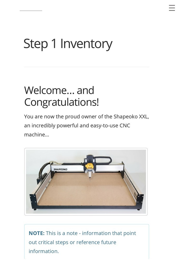
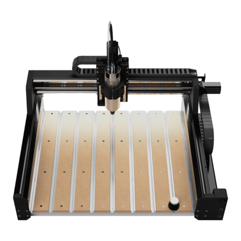
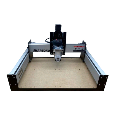
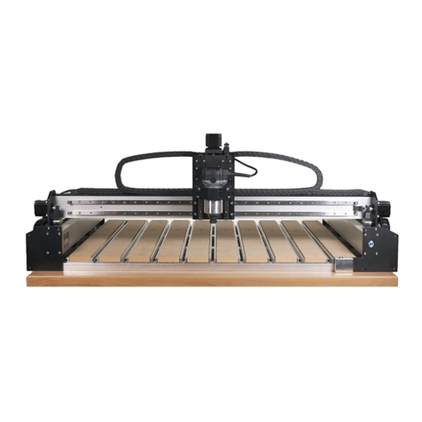
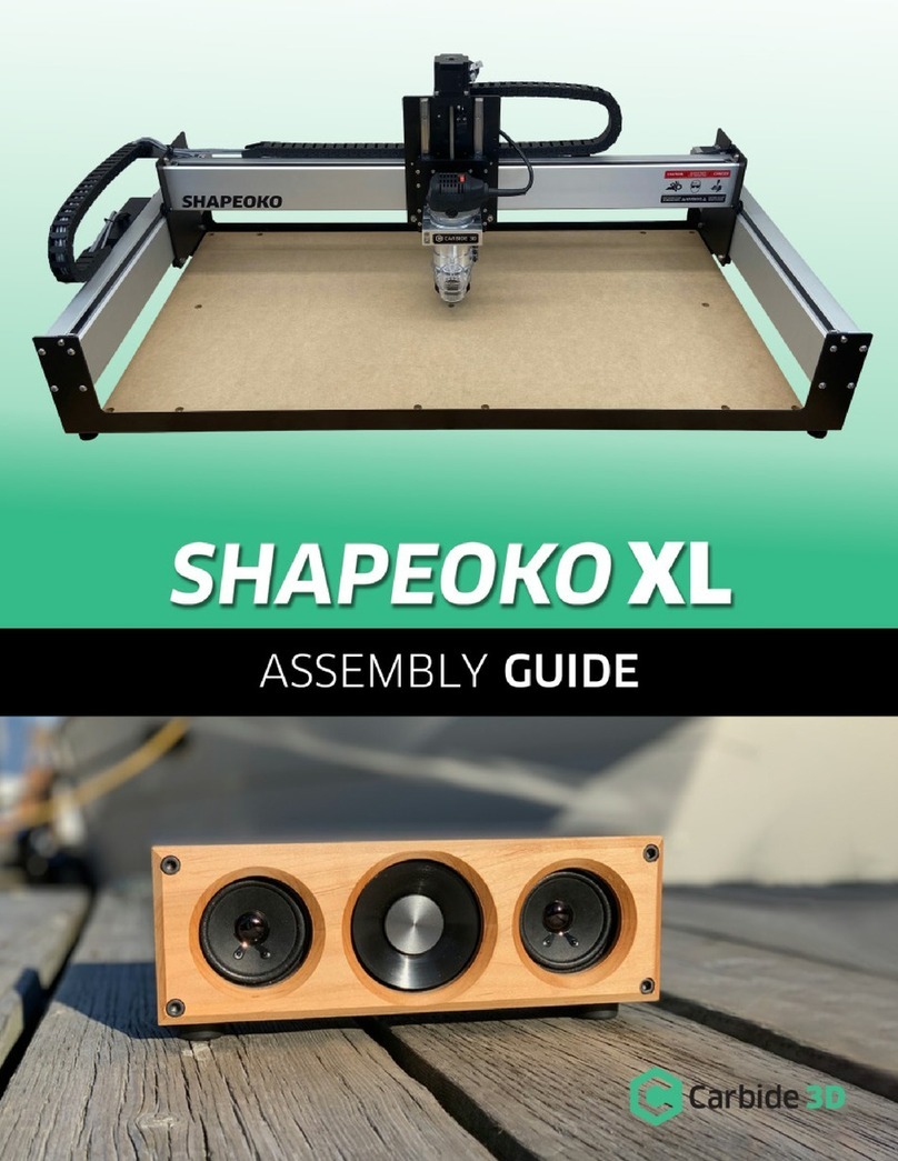
Carbide 3D Shapeoko 5 Pro User manual

Shapeoko 5 Pro
CNC Router
Assembly Guide

WELCOME AND CONGRATULATIONS .............................................................. 2
INVENTORY..................................................................................... 3
STEP 1.......................................................................................... 4
1.1 Unpack Box 1 ........................................................................................................................................................................................................................5
1.2 Position Baseframe.............................................................................................................................................................................................................5
1.3 Install Y-Right Assembly.....................................................................................................................................................................................................6
1.4 Install Y-Left Assembly ....................................................................................................................................................................................................... 7
1.5 Install the Cable Track........................................................................................................................................................................................................8
1.6 Prepare for Gantry Install ..................................................................................................................................................................................................8
1.7 Open Box 2...........................................................................................................................................................................................................................9
1.8 Install Gantry Assembly .....................................................................................................................................................................................................9
1.9 Square the Machine .......................................................................................................................................................................................................... 11
STEP 2 .........................................................................................12
2.1 Install the HDZ.....................................................................................................................................................................................................................13
2.2 Install X-Axis Stepper Motor............................................................................................................................................................................................14
STEP 3 .........................................................................................16
3.1 Install Extrusions.................................................................................................................................................................................................................17
3.2 Install MDF Strips................................................................................................................................................................................................................17
STEP 4 .........................................................................................18
4.1 Install Wiring Harness....................................................................................................................................................................................................... 19
4.2 Install YL Wire Keeper...................................................................................................................................................................................................... 21
4.3 Connect Front Plate......................................................................................................................................................................................................... 22
4.4 Install YR Wire Keeper .................................................................................................................................................................................................... 23
4.5 Attach Cables at Y-Right................................................................................................................................................................................................. 24
4.6 Install Y-Right End Cap.................................................................................................................................................................................................... 26
4.7 Connect Z-Axis Cables ....................................................................................................................................................................................................27
4.8 Connect Y-Left Motor and Limit Cables ..................................................................................................................................................................... 28
4.9 Connect Y-Right Motor and Limit Cables.................................................................................................................................................................. 29
4.10 Install Grounding Block................................................................................................................................................................................................... 30
4.11 Connect Front Plate Extension .......................................................................................................................................................................................31
STEP 5 ........................................................................................ 32
5.1 Preparing the Router Drag Chains................................................................................................................................................................................33
5.2 Insert Power Cable............................................................................................................................................................................................................33
5.3 Install the Drag Chains.....................................................................................................................................................................................................34
5.4 Secure Router & Cable ................................................................................................................................................................................................... 35
5.5 Install Y-Left End Cap....................................................................................................................................................................................................... 35
STEP 6 ........................................................................................ 36
6.1 Connect the Controller ....................................................................................................................................................................................................37
6.2 Install the BitSetter........................................................................................................................................................................................................... 38
6.3 Tidy Up................................................................................................................................................................................................................................ 39
Table of Contents

Shipping Box 2 Contains
X-Axis Gantry Assembly Hybrid Table Extrusions and MDF Strips (Nested Together)
Hybrid Table Hardware Box
Shipping Box 1 Contains
Open Me First Box
• Tool Bag
• Extra Hardware Bag
• Zip Ties & Cable Ties
• #201 0.25″ Flat Endmill
• Workholding Kit
• Sweepy 65 V2.0 Box
• Sharpie
HDZ (Z-Axis) Box
• Pre-assembled HDZ (Z-Axis)
• HDZ Hardware Bag
• End Caps (Y-Left and Y-Right)
• End Cap Hardware Bag
• X-Axis Stepper Motor
• X-Axis Stepper Motor Hardware Bag
S5 Electronics Box
• Wiring Harness Box
• Wiring Harness
• Drag Chain Hardware Bag
• X- and Y-Axis Router Drag Chains
• Front Plate Extension Cable
• Grounding Block and Hardware
• Power Pendant Box
• Power Pendant
• Power Pendant Extension Cable
• Controller Box
• Controller
• USB Cable
• 3-prong Power Cable
• BitSetter Box
• BitSetter
• BitSetter Hardware
• BitSetter Extension Cable
Y-Left Assembly
Y-Axis Assembly Hardware Bag Y-Right Assembly
Baseframe Box
• Baseframe Members
Cable Track (Underneath Baseframe Box)
Inventory
PRO TIP: Your Shapeoko5Pro kit has been carefully packaged by hand. If you find that you’re missing hardware
in any step, check the extra hardware bag included in the Open Me First Box. If you don’t find what you need in the
extra hardware bag, or one of your components was damaged in shipping, contact us at [email protected]
and we’ll ship you a replacement ASAP.
Welcome and Congratulations
The Shapeoko5Pro is a high-performance CNC router that comes with everything you need to accurately
cut wood, plastic, and aluminum, so you can turn your workbench into a business. At up to 4 feet in width,
Shapeoko5Pro is bigger than ever, so you can take on larger jobs or nest more parts together and run the
machine longer. It’s not just a CNC router, it’s a complete system of hardware, software, accessories, and
training, built and supported in the USA.
Assembly Notes
• We’ll walk you through the assembly process step-by-step in this guide. Precision-machined parts and
pre-assembled components, mean quicker assembly, in fewer steps!
• The use of power tools is not recommended for assembly. Use hand tools only.
• Some steps rely on non-tightened fasteners. Do not tighten fasteners beyond finger-tight until instructed.
• See the Glossary of Terms at the end of this guide for common CNC terms and definitions.
• Your Shapeoko5Pro gantry is powered by stepper motors. When the power is o, moving the motors by
hand will cause them to generate electricity. IMPORTANT: When moving the gantry by hand, go slowly. The
power generated by the stepper motors will feel like bumps. If the red LED on the controller lights up when
moving the stepper motors, it’s important to slow down because you are pushing electricity back through the
board. Too much backflow could damage the controller.
Software Requirements
The Shapeoko5Pro controller must be used with the latest version of Carbide Motion.
Support, Warranty, and Training
Technical Support
Have questions? Need help? We have a fully-staed support team waiting to help if you run into any trouble
One-Year Warranty
Your Shapeoko5Pro comes with a one-year warranty against defects. If you have any problems, we’ll take care
of them. See the full warranty at carbide3d.com/policy/warranty.
30-Day, “Mistakes Are on Us” Guarantee
We want you to jump into your new Shapeoko CNC router without any fear of damaging anything so our
warranty includes the following benefit: for the first 30 days that you own your Shapeoko, we’ll replace any
Carbide 3D-branded item that’s damaged, even if it’s your fault. Details about what’s covered can be found at
shop.carbide3d.com/pages/mistakes-are-on-us.
Free 1-on-1 Training Sessions
Your Shapeoko5Pro comes with four FREE 30-minute 1-on-1 training sessions with a Carbide 3D expert via
video chat.
Training Videos and More
Access training videos, design resources, and more at my.carbide3d.com.

Items Needed in Step 1
Description Qty
Baseframe Members 4
Y-Right Assembly 1
Y-Left Assembly 1
Y-Axis Assembly Hardware: M6×16mm Button Head Cap Screws 16
Tool Bag 1
Cable Track 1
X-Axis Gantry Assembly 1
1.1 Unpack Box 1
1. In Box 1, locate the box labeled Open Me First,
remove the tool bag, and set the box aside.
2. Locate the S5 Electronics and HDZ boxes and
set them aside.
3. Locate the Baseframe box between the two
Y-Rails at the bottom of Box 1 and remove it.
4. Open the Baseframe box and remove the four
baseframe members.
Figure 1-1
1.2 Position Baseframe
1. Position the four baseframe members
horizontally across your table about 15.7 inches
apart, center to center. See Figure 1-1.
a. The wire clips face to the right.
2. Open the wire clip on the end of each
baseframe member.

1.3 Install Y-Right Assembly
NOTE: This step is much easier with two people.
The Y-assembly is heavy and can easily tip over if set
upright before attaching it to the baseframe.
1. Locate the Y-Right assembly and the hardware
bag in the bottom of Box 1.
a. Y-Right has a Carbide 3D logo on the front
plate.
2. Set the Y-Right assembly on the right side of the
baseframe. See Fig. 1-2.
a. Align the front edge with the front edge of
the first baseframe member.
b. Align with the last set of screw holes in each
baseframe member.
Figure 1-2
1.4 Install Y-Left Assembly
NOTE: This step is much easier with two people.
The Y-assembly is heavy and can easily tip over if set
upright before attaching it to the baseframe.
1. Locate the Y-Left assembly in the bottom of
Box1.
a. Y-Left has a blank front plate.
2. Set the Y-Left assembly on the left side of the
baseframe. See Fig. 1-3.
a. Align the front edge with the front edge of
the first baseframe member.
b. Align with the last set of screw holes in each
baseframe member.
Figure 1-3
3. Use a 4mm hex key and eight (8) M6×16mm
BHCS to attach the assembly. See Fig. 1-3.
Snug the screws but don’t fully tighten.
a. Y-Left assembly is attached in four locations.
b. At location 1, the BHCS insert through the
holes in the end cap.
NOTE: Don’t worry about squaring the baseframe
yet.
3. Use a 4mm hex key and eight (8) M6×16mm
BHCS to attach the Y-assembly. See Fig. 1-2.
Snug the screws but don’t fully tighten.
a. Y-Right assembly is attached in four
locations.
b. At location 1, the BHCS insert through the
holes in the end cap.
NOTE: Don’t worry about squaring the baseframe
yet.

Figure 1-4 Figure 1-5
1.5 Install the Cable Track
1. Locate the cable track in the bottom of Box 1.
2. Install the cable track to the last baseframe
member at the back of the machine.
a. Remove the protective coating.
b. Remove the blue adhesive cover.
c. Position with the opening facing up.
d. Align to the bottom edge of the baseframe.
e. Align between the two Y-Axis assemblies,
there will be about 4.5 inches on either side.
f. From one side, press firmly as you run your
hand over the entire length of the track.
3. Open the cable track.
1.6 Prepare for Gantry
Install
1. Pull the Y-Right carriage all the way to the front
of the machine. See Fig. 1-4.
2. Pull the Y-Left carriage all the way to the front.
3. Use a 5mm hex key to remove the two (2)
M6×20mm SHCS from the rear position of the
Y-Right and Y-Left carriages.
NOTE: Keep the M6×20mm SHCS close by. You will
need them to install the gantry.
1.7 Open Box 2
1. Open Box 2. This box contains:
a. Shapeoko 5 Pro gantry (note that the X-Axis
drag chain is pre-installed on the gantry).
b. Shapeoko 5 Hybrid Table (aluminum
extrusions and MDF strips).
c. Hybrid Table hardware.
1.8 Install Gantry Assembly
NOTE: This step is much easier with two people.
The X-Axis gantry assembly is heavy and can easily
tip over. If the gantry tips over, the mating faces on
the bottom edge will be irreparably damaged, which
will prevent the gantry from attaching properly to the
Y-Axis assemblies.
1. Lift the gantry from the box and set it onto the
rear position of the Y-Axis carriage plates, over
the now-empty screw holes. See Fig. 1-5.
a. The large X-Axis carrier plate faces the front.
2. Hold the gantry firmly in place as you complete
the steps on the following page.

3. From the right side of the machine, push the
gantry toward the front of the machine until it
engages with the reference edge on the top of
the Y-Right carriage plate. See Fig.1-6.
4. Orient the cross dowels so that the reference
line on the face of each is vertical. See Fig.1-7.
5. Use a 5mm hex key to loosely re-insert the two
(2) M6×20mm SHCS to attach the gantry to the
Y-Right assembly. See Fig.1-7.
6. From the left side of the machine, push the
gantry forward until it engages with the
reference edge on the top of the Y-Right
carriage plate.
Figure 1-6
1.9 Square the Machine
1. Check that the Y-Right and Y-Left carriages
are still pushed all the way to the front of the
machine.
2. Starting on the right side, use a 4mm hex key
to fully tighten the first pair of M6×16mm BHCS
to secure the Y-Right assembly to the first
baseframe member.
3. Moving to the left side, use a 4mm hex key to
fully tighten the first pair of M6×16mm BHCS.
4. Push the gantry back to the second baseframe
member and fully tighten the pair of screws on
the right side, then on the left side.
Figure 1-7
5. Push the gantry back to the third baseframe
member and tighten the screws on the right,
then on the left.
6. Push the gantry all of the way to the back of
the machine until it hits the Y-motor mounts and
tighten the screws on the right, then on the left.
NOTE: The Y-Left extrusion is slotted. When
attaching the left side of the gantry, you can slide the
Y-Left extrusion inward/outward ± 2mm to align the
gantry with the cross dowels.
7. Orient the cross dowels so that the reference
line on the face of each is vertical. See Fig.1-7.
8. Use a 5mm hex key to loosely re-insert the two
(2) M6×20mm SHCS to attach the gantry.
9. Ensure the both Y-carriage plates are still in the
furthest forward position.
10. Keep pressure on the gantry to keep it engaged
with the reference edge on each carriage as you
fully tighten all four (4) M6×20mm SHCS.
Reference Edge
Keep gantry
engaged with the
reference edge.
Cross Dowel
M6×20 SHCS
Reference Line
Reference Edge
Gantry

Items Needed in Step 2
Description Qty
HDZ (Z-Axis Assembly) 1
HDZ Hardware: M6×20mm Socket Head Cap Screws 4
X-Axis Stepper Motor 1
X-Motor Hardware: M5×10mm Socket Head Cap Screws 4
2.1 Install the HDZ
1. Open the HDZ box and remove the assembled
HDZ (Z-Axis Assembly), HDZ hardware, X-Axis
stepper motor, X-Axis stepper motor hardware.
2. Set the Y-Left and Y-Right end caps and
hardware aside. You will not need them until
STEP 4 and STEP 5.
3. Align the HDZ with the two short locating pins
on the front of the X-Axiscarrier plate and push
it onto the carrier plate. See Fig.2-1.
a. Z-Axis stepper motor on top.
Figure 2-1
b. The HDZ slides onto the two locating pins.
Note that it may not slide all the way
onto the pins until the four SHCS are fully
tightened.
4. Hold the HDZ in place as you loosely insert four
(4) M6×20mm SHCS. See Fig.2-1.
NOTE: Do not let go of the HDZ until at least two of
the SHCS are installed.
5. Use a 5mm hex key to fully tighten the SHCS
and secure the HDZ to the carrier plate.

2.2 Install X-Axis Stepper
Motor
1. Locate the X-motor in the HDZ box.
2. Orient the X-motor with the motor coupler facing
toward the mount. See Fig.2-2.
a. Motor wires face the rear of the machine.
See Fig.2-3.
3. Rotate the motor shaft until the motor coupler is
lined up with the ball-screw coupler inside the
mount.
Figure 2-2 Figure 2-4
4. Press the couplers together until fully seated
and the motor is flush with the motor mount. See
Fig.2-4.
5. Use a 4mm hex key and four (4) M5×10mm
SHCS to secure the X-motor to the motor mount.
Fully tighten.
Figure 2-3

Items Needed for Step 3
Description Qty
Hybrid Extrusion 10
M6×10mm Flat Head Screws 80
MDF Strip 10
M6×20mm Socket Head Cap Screws 40
3.1 Install Extrusions
1. Locate the aluminum extrusions, MDF strips, and
the small hardware box inside Box2. The MDF
strips are nested inside the extrusions.
2. Lay the ten (10) aluminum Hybrid Table
extrusions across the baseframe, front to back.
3. Use a 4mm hex key and eight (8) M6×10mm FHS
to loosely attach each extrusion. See Fig.3-1.
a. Insert screws in order: front, back, center.
4. Fully tighten all screws to secure the extrusions.
NOTE: We do not recommend using power tools
here; the risk of cross-threading is too high.
Figure 3-2
3.2 Install MDF Strips
1. Position the ten (10) MDF strips inside the Hybrid
Table extrusions. See Fig.3-2.
2. Use a 5mm hex key and four (4) M6×20mm
SHCS to loosely attach each MDF strip.
a. Insert screws in order: front, back, center.
3. Fully tighten all screws to secure the MDF strips.
Figure 3-1
M6×20mm SHCS

Figure 4-1 Figure 4-2
Items Needed in Step 4
Description Qty
Wiring Harness 1
Drag Chain Hardware: M3×6mm Socket Head Cap Screws 4
Front Plate Extension Cable (3-pin Male to 4-pin Male) 1
Y-Right End Cap 1
Top End Cap Hardware: M6×30mm Socket Head Cap Screw 1
Bottom End Cap Hardware: M6×12mm Socket Head Cap Screw 1
Wire Keeper Hardware: M6×16mm Button Head Cap Screws 4
4.1 Install Wiring Harness
The wiring is pre-made, pre-tested, and is an exact
fit for your machine. The wiring harness has several
dierent branches: Z-Axis, X/Z/LED, front plate, Y-Left,
Y-Right, and the controller. See Fig.4-1.
1. Locate the wiring harness and drag chain
hardware bag in the Wiring Harness box (inside
the S5 Electronics box).
2. Unroll and lay the wiring harness across the
baseframe, from front-to-back.
a. The five connectors and the grounding wire
loop go to the front (the head).
b. The wiring harness trunk, the long cable
bundle, goes to the back (the tail).
3. Lift the drag chain, slide it under the gantry, and
place it on top of the Y-Right assembly.
4. Curl the head of the wiring harness up so that it
rests on the bracket on the back of the Y-Right
carriage plate. See Fig.4-2.
5. Use a 2.5mm hex key and two (2) M3×6mm
SHCS to secure the drag chain head to the
bracket. Fully tighten. See Fig.4-2.
M3×6mm SHCS

Figure 4-3 Figure 4-4
5. Use a 4mm hex key and two (2) M6×16mm BHCS
to attach the wire keeper to the Y-Left assembly.
Fully tighten. See Fig.4-4.
6. Open the cable track on the last baseframe
member and slide the wires in, extending them
all the way to Y-Right.
7. Snap the cover back in place to close the cable
track.
a. Make sure all wires are completely in the
track and that no wires are getting pinched.
6. Use a 2.5mm hex key and two (2) M3×6mm
SHCS to secure the tail of the drag chain at the
rear of the Y-Right assembly. Fully tighten. See
Fig.4-3.
7. Put the drag chain hardware bag, with the
remaining screws, back in the Wiring Harness
box. You’ll need them when we install the router
drag chains in Step 5.
4.2 Install YL Wire Keeper
1. Move to the back of the machine.
2. Locate the long Y-Left wiring bundle extending
from the wiring harness trunk. It has two plastic
rectangular wire keepers attached.
3. Locate the Y-Left wire keeper at the end of the
cables. “YL” is printed on the bottom side.
4. Slide the wire keeper under the back edge of
the Y-Left assembly (right side when standing at
the back of the machine). See Fig.4-4.
a. The wires face up.
b. Align the screw holes in the wire keeper with
those in the assembly.
Y-Left Wire Keeper
M3×6mm SHCS

Figure 4-5 Figure 4-6
4.3 Connect Front Plate
1. Locate the front plate extension cable (3-pin to
4-pin) in the Wiring Harness box.
2. Plug the cable’s 3-pin connector into the 3-pin
connector on the back side of the front plate.
See Fig.4-5.
3. Moving backwards, keep tension on the cable
as you snap each wire clip on the ends of the
baseframe members over the cable.
4. Direct the end of the cable past the final
baseframe member and under the end of the
Y-Right assembly.
5. Plug the extension cable into the 4-pin, single
row connector exiting the wiring harness at the
back of the machine.
4.4 Install YR Wire Keeper
1. Locate the Y-Right wire keeper. It has “YR”
printed on the bottom side.
2. Set the front plate extension cable into the wire
keeper. See Fig.4-6.
3. Slide the wire keeper under the back edge of
the Y-Right assembly. See Fig.4-6.
a. The wires face up.
b. Align the screw holes in the wire keeper with
those in the assembly.
4. Use a 4mm hex key and two (2) M6×16mm
BHCS to attach the wire keeper to the Y-Right
assembly. Fully tighten.
Y-Right Wire Keeper
Front Plate
Extension Cable

4.5 Attach Cables at Y-Right
NOTE: Connectors are polarized and will only
connect one way. Do not force a connection. Be sure
the connectors are properly oriented with the locking
tabs aligned before plugging them in. See Fig.4-8.
1. Move to the Y-Right side of the gantry.
a. Five cables exit the wiring harness head at
Y-Right: LED, X-motor, Z-motor, Z-limit switch,
and X-limit switch.
b. Each cable has a dierent connector type, so
there is only one match for each connector.
2. Connect the gantry LED. See Figs.4-7 and 4-9.
a. LED connectors are 2-pin, dual-row (vertical).
b. The LED cable exits the end of the gantry.
c. Align the locking tabs for proper orientation.
3. Connect the X-Axis stepper motor.
a. X-motor connectors are 4-pin, dual-row.
b. Align the locking tabs for proper orientation.
4. Connect the X-Axis limit switch.
a. X-limit switch connectors are 3-pin, single-
row.
b. Align the locking tabs for proper orientation.
Figure 4-7 Figure 4-9
5. Connect the Z-Axis stepper motor.
a. Z-motor connectors are 6-pin, dual-row.
b. Align the locking tabs for proper orientation.
6. Connect the Z-Axis limit switch.
a. Z-limit switch connectors are 4-pin, single-
row.
b. Align the locking tabs for proper orientation.
7. Direct all five wires below the X-Axis motor
mount, then tuck them into the open end of the
gantry extrusion.
Figure 4-8

4.6 Install Y-Right End Cap
1. Gather the Y-Right end cap and hardware, one
M6×30mm and one M6×12mm SHCS.
2. Make sure the wiring at Y-Right is tucked into the
cavity in the extrusion.
3. Place the right end cap on the Y-Right end of the
gantry extrusion. See Fig.4-10.
a. The long straight edge goes to the back.
b. Be careful not to pinch the wires behind the
end cap.
4. Use a 5mm hex key to insert one (1) M6×30mm
SHCS through the top screw hole.
Figure 4-10 Figure 4-11
5. Locate the green and yellow grounding wire
exiting the wiring harness at the head.
6. Place the loop at the end of the grounding wire
onto the end of the M6×12mm SHCS.
7. Use a 5mm hex key to insert the M6×12mm
SHCS through the bottom screw hole in the end
cap. See Figs.4-10 and Fig.4-12.
4.7 Connect Z-Axis Cables
1. At the back of the HDZ, connect the Z-Axis
motor and Z-Axis limit switch cables. See
Fig.4-11.
a. Z-motor connectors are 4-pin, dual row.
b. Z-limit switch connectors are 3-pin, single
row.
Figure 4-12
Grounding Wire
M6×12 SHCS
Z-Motor
Z-Limit Switch

4.8 Connect Y-Left Motor
and Limit Cables
1. Move to back of the machine at Y-Left (right side
of the machine from the back).
2. Locate the two connectors, 4-pin Y-Left-motor
and 3-pin Y-Left-limit switch, exiting from the
Y-Left wire keeper.
3. Connect the Y-Left stepper motor. See Fig.4-13.
a. YL-motor connectors are 4-pin, dual-row.
b. Align the locking tabs for proper orientation.
4. Connect the Y-Left limit switch. See Fig.4-13.
a. YL-limit switch connectors are 3-pin, single-
row.
b. Align the locking tabs for proper orientation.
4.9 Connect Y-Right Motor
and Limit Cables
1. Move to the Y-Right side of the machine.
2. Locate the two Y-Right cables (one 4-pin and
one 3-pin) exiting the wiring harness trunk.
3. Connect the Y-Right stepper motor. See
Fig.4-14.
a. YR-motor connectors are 4-pin, dual-row.
b. Align the locking tabs for proper orientation.
4. Connect the Y-Right limit switch. See Fig.4-14.
a. YR-limit switch connectors are 3-pin, single-
row.
b. Align the locking tabs for proper orientation
Figure 4-13 Figure 4-14
Y-Left Limit
Switch
Y-Right Limit
Switch
Y-Left Motor
Y-Right Motor

4.10 Install Grounding Block
1. Locate the grounding block and its hardware in
the Grounding Block bag.
2. Position the grounding block on the inside of the
Y-Right assembly, at the rear. See Fig.4-15.
a. Six non-threaded holes face the rear.
b. Two threaded holes face up.
3. Use a 3mm hex key and two (2) M4×30mm
BHCS to attach the grounding block to the
inside of the Y-Right assembly. See Fig.4-15.
4. Locate the green and yellow cable with the
banana plug exiting the wiring harness.
5. Insert the banana plug into any of the six
non-threaded holes on the rear face of the
grounding block.
4.11 Connect Front Plate
Extension
1. Locate the end of the front plate extension
(4-pin, single-row) at the back of the machine at
Y-Right.
2. Connect the extension cable to the 4-pin, single
row connector exiting the wiring harness.
a. Align the locking tabs for proper orientation.
Figure 4-15

Items Needed in Step 5
Description Qty
X- and Y-Axis Router Drag Chains 2
Router / Spindle (Optional Purchase) 1
Drag Chain Hardware: M3×6mm SHCS (6); M4×6mm BHCS (2) 1
Y-Left End Cap 1
Top End Cap Hardware: M6×30mm Socket Head Cap Screw 1
Bottom End Cap Hardware: M6×12mm Socket Head Cap Screw 1
5.1 Preparing the Router
Drag Chains
1. Locate the two empty router drag chains in the
Wiring Harness box.
2. Lay the drag chains flat, hinge-side up, side by
side on the baseframe. See Fig.5-1.
a. The X-Axis router drag chain has two more
links than the Y-Axis drag chain.
3. Use a large hex key to pry open the link hinges
on both drag chains.
4. Use a small flathead screwdriver to pry the head
link and tail link o each drag chain and set
them aside.
5.2 Insert Power Cable
1. Place the router at the head end of the X-Axis
(longer) drag chain.
2. Lay the router power cable in the X-Axis drag
chain and close the first and last links to hold the
cable in place. See Fig.5-1.
3. Lay the cable in the Y-Axis (shorter) drag chain.
4. Close the first and last links of the Y-Axis drag
chain to hold the cable in place.
5. Snap closed the remaining links in both drag
chains.
6. Snap the head and tail links back onto both drag
chains.
Figure 5-1

5.3 Install the Drag Chains
NOTE: When installing the drag chains, if a head or
tail link is upside down, simply pry it o with a small
screwdriver and reattach it, flat side to the rail.
1. Lift the drag chains and router and move them
to the front of the machine.
2. Insert the router/spindle as far as it will go into
the spindle mount on the front of the HDZ.
3. Lift the X-Axis (longer) drag chain over the HDZ
and set it on top of the gantry. See Fig.5-2.
4. Lift the Y-Axis (shorter) drag chain and set it onto
the Y-Left assembly (it slides under the gantry).
See Fig.5-3.
Figure 5-2
5.4 Secure Router & Cable
1. Orient the router in the spindle mount so that
the power cable extends toward Y-Left.
2. Use a 5mm hex key to tighten the four (4) M6
screws, securing the router in the spindle mount.
3. Push the HDZ down to the bottom of travel.
a. Make sure there is enough power cable to
allow the HDZ to move freely and to prevent
binding during travel.
4. Use a zip tie to secure the router power cable to
the head end of the X-Axis router drag chain.
5. Use a zip tie to secure the router power cable to
the tail end of the X-Axis router drag chain.
Figure 5-3
5.5 Install Y-Left End Cap
1. Gather the Y-Left end cap and hardware, one
M6×30mm SHCS and one M6×12mm SHCS.
2. Route the router power cable down over the
edge of the gantry.
3. Place the end cap over the Y-Left end of the
gantry and the power cable.
a. The long straight edge goes to the back.
4. Use a 5mm hex key to insert one (1) M6×30mm
SHCS through the top screw hole and one (1)
M6×12mm SHCS through the bottom screw hole.
5. Use a 2.5mm hex key and two (2) M3×6mm
SHCS to secure the X-Axis (longer) drag chain
head to the bracket on the back of the HDZ.
Fully tighten.
6. Use a 2.5mm hex key and two (2) M4×6mm
BHCS to secure the X-Axis drag chain tail to the
Y-Left end of the gantry. Fully tighten.
7. Use a 2.5mm hex key and two (2) M3×6mm
SHCS to secure the Y-Axis (shorter) drag chain
head to the Y-Left carriage. Fully tighten.
8. Use a 2.5mm hex key and two (2) M3×6mm
SHCS to secure the Y-Axis drag chain tail to the
Y-Left assembly. Fully tighten.

Items Needed in Step 6
Description Qty
Controller 1
Power Pendant 1
Power Pendant Extension Cable (8-pin Male to 6-pin Male) 1
USB Cable 1
3-Prong Controller Power Cable 1
BitSetter 1
BitSetter Hardware: M6×30mm (2) and Teez Nuts (2) 4
BitSetter Extension Cable (3-pin Male to 3-pin Male) 1
6.1 Connect the Controller
1. Locate the Controller box, Power Pendant box,
and USB cable in the S5 Electronics box.
2. Plug the 18-pin motor wiring bundle connector
into the larger 18-pin “MOTORS” port on the
controller. See Fig.6-1.
3. Plug the 22-pin limit switch wiring bundle
connector into the smaller 22-pin “SWITCHES”
port on the controller. See Fig.6-1.
4. Plug the 8-pin end of the power pendant cable
into the port labeled “POWER PENDANT” on the
controller.
5. Plug the 6-pin end of the power pendant cable
into the power pendant.
a. Align the locking tabs for proper orientation.
6. Plug the USB cable into the port labeled “USB”.
7. Plug the 3-prong power cable into the power
jack on the side of the controller.
Figure 6-1
Table of contents
Other Carbide 3D Control System manuals
Popular Control System manuals by other brands

Portos
Portos DC1 user manual

Woodway
Woodway Opti-Link Installation & operation

D.Electron
D.Electron CNC Z32 Florenz Series Programming guide

Bryant
Bryant ZONE PERFECT PLUS ZONEBB2KIT Zoning Design Guide

Weil-McLain
Weil-McLain BMC Install and operation instructions

DSE
DSE DSEG8680 installation instructions