Carel EVD evolution User manual


Integrated Control Solutions & Energy Savings
EVD evolution
NO POWER
& SIGNAL
CABLES
TOGETHER
READ CAREFULLY IN THE TEXT!
User manual
electronic expansion valve driver


3
ENG
“EVD evolution”+0300005EN - rel. 3.1 - 25.07.2011
WARNINGS
CAREL bases the development of its products on decades of experience
in HVAC, on the continuous investments in technological innovations
to products, procedures and strict quality processes with in-circuit and
functional testing on 100% of its products, and on the most innovative
production technology available on the market. CAREL and its subsidiaries
nonetheless cannot guarantee that all the aspects of the product and the
software included with the product respond to the requirements of the nal
application, despite the product being developed according to start-of-the-
art techniques. The customer (manufacturer, developer or installer of the nal
equipment) accepts all liability and risk relating to the conguration of the
product in order to reach the expected results in relation to the specic nal
installation and/or equipment. CAREL may, based on specic agreements, acts
as a consultant for the positive commissioning of the nal unit/application,
however in no case does it accept liability for the correct operation of the nal
equipment/system.
The CAREL product is a state-of-the-art product, whose operation is specied
in the technical documentation supplied with the product or can be
downloaded, even prior to purchase, from the website www.carel.com.
Each CAREL product, in relation to its advanced level of technology, requires
setup/conguration/programming/commissioning to be able to operate in
the best possible way for the specic application.The failure to complete such
operations, which are required/indicated in the user manual, may cause the
nal product to malfunction; CAREL accepts no liability in such cases.
Only qualied personnel may install or carry out technical service on the
product.
The customer must only use the product in the manner described in the
documentation relating to the product.
In addition to observing any further warnings described in this manual, the
following warnings must be heeded for all CAREL products:
• prevent the electronic circuits from getting wet. Rain, humidity and all
types of liquids or condensate contain corrosive minerals that may damage
the electronic circuits. In any case, the product should be used or stored
in environments that comply with the temperature and humidity limits
specied in the manual;
• do not install the device in particularly hot environments. Too high
temperatures may reduce the life of electronic devices, damage them and
deform or melt the plastic parts. In any case, the product should be used
or stored in environments that comply with the temperature and humidity
limits specied in the manual;
• do not attempt to open the device in any way other than described in the
manual;
• do not drop, hit or shake the device, as the internal circuits and mechanisms
may be irreparably damaged;
• do not use corrosive chemicals, solvents or aggressive detergents to clean
the device;
• do not use the product for applications other than those specied in the
technical manual.
All of the above suggestions likewise apply to the controllers, serial boards,
programming keys or any other accessory in the CAREL product portfolio.
CAREL adopts a policy of continual development. Consequently, CAREL
reserves the right to make changes and improvements to any product
described in this document without prior warning.
The technical specications shown in the manual may be changed without
prior warning.
The liability of CAREL in relation to its products is specied in the CAREL general
contract conditions, available on the website www.carel.com and/or by
specic agreements with customers; specically, to the extent where allowed
by applicable legislation, in no case will CAREL, its employees or subsidiaries
be liable for any lost earnings or sales, losses of data and information, costs of
replacement goods or services, damage to things or people, downtime or any
direct, indirect, incidental, actual, punitive, exemplary, special or consequential
damage of any kind whatsoever, whether contractual, extra-contractual or
due to negligence, or any other liabilities deriving from the installation, use or
impossibility to use the product, even if CAREL or its subsidiaries are warned
of the possibility of such damage.
DISPOSAL
INFORMATION FOR USERS ON THE CORRECT
HANDLING OF WASTE ELECTRICAL AND ELEC-
TRONIC EQUIPMENT (WEEE)
In reference to European Union directive 2002/96/EC issued on 27 January
2003 and the related national legislation, please note that:
1. WEEE cannot be disposed of as municipal waste and such waste must be
collected and disposed of separately;
2. thepublicorprivatewastecollectionsystemsdenedbylocallegislationmust
be used. In addition, the equipment can be returned to the distributor at
the end of its working life when buying new equipment;
3. the equipment may contain hazardous substances: the improper use or
incorrect disposal of such may have negative eects on human health
and on the environment;
4. the symbol (crossed-out wheeled bin) shown on the product or on the
packaging and on the instruction sheet indicates that the equipment has
been introduced onto the market after 13 August 2005 and that it must
be disposed of separately;
5. intheeventofillegaldisposalofelectricaland electronicwaste,thepenalties
are specied by local waste disposal legislation.
Warranty on the materials: 2 years (from the date of production, excluding
consumables).
Approval: the quality and safety of CAREL INDUSTRIES products are
guaranteed by the ISO 9001 certied design and production system, as well
as by the marks (*).
WARNING: separate as much as possible the probe and digital input signal
cables from the cables carrying inductive loads and power cables to avoid
possible electromagnetic disturbance.
Never run power cables (including the electrical panel wiring) and signal
cables in the same conduits.
NO POWER
& SIGNAL
CABLES
TOGETHER
READ CAREFULLY IN THE TEXT!


5
ENG
“EVD evolution”+0300005EN - rel. 3.1 - 25.07.2011
Content
1. INTRODUCTION 7
1.1 Models ............................................................................................................ 7
1.2 Functions and main characteristics............................................................. 7
2. INSTALLATION 9
2.1 DIN rail assembly and dimensions............................................................. 9
2.2 Description of the terminals......................................................................... 9
2.3 Connection diagram - superheat control .................................................. 9
2.4 Installation ...................................................................................................... 10
2.5 Valve operation in parallel and complementary mode........................ 10
2.6 Shared pressure probe................................................................................ 11
2.7 Connecting the USB-tLAN converter........................................................ 11
2.8 Connecting the USB/RS485 converter..................................................... 11
2.9 Upload, Download and Reset parameters (display)............................. 11
2.10 Show electrical connections (display)...................................................... 12
2.11 General connection diagram...................................................................... 12
3. USER INTERFACE 13
3.1 Assembling the display board (accessory).............................................. 13
3.2 Display and keypad...................................................................................... 13
3.3 Display mode (display) ............................................................................... 14
3.4 Programming mode (display).................................................................... 14
4. COMMISSIONING 15
4.1 Commissioning.............................................................................................. 15
4.2 Guided commissioning procedure (display).......................................... 15
4.3 Checks after commissioning........................................................................17
4.4 Other functions...............................................................................................17
5. CONTROL 18
5.1 Main and auxiliary control........................................................................... 18
5.2 Superheat control ......................................................................................... 18
5.3 Adaptive control and autotuning............................................................... 19
5.4 Control with Emerson Climate Digital Scroll™ compressor ...............20
5.5 Control with SIAM ANB scroll compressor.............................................. 21
5.6 Superheat regulation with 2 temperature probes................................. 21
5.7 Advanced regulation ....................................................................................22
5.8 Auxiliary control ............................................................................................24
6. FUNCTIONS 27
6.1 Power supply mode .....................................................................................27
6.2 Network connection.....................................................................................27
6.3 Inputs and outputs .......................................................................................27
6.4 Control status ................................................................................................28
6.5 Advanced control status ..............................................................................30
7. PROTECTORS 32
7.1 Protectors........................................................................................................32
8. PARAMETERS TABLE 35
8.1 Unit of measure.............................................................................................39
8.2 Variables accessible via serial connection ...............................................40
8.3 Variables used based on the type of control......................................... 41
9. ALARMS 42
9.1 Alarms..............................................................................................................42
9.2 Alarm relay configuration............................................................................43
9.3 Probe alarms..................................................................................................43
9.4 Control alarms ...............................................................................................44
9.5 EEV motor alarm...........................................................................................44
9.6 LAN error alarm.............................................................................................45
10. TROUBLESHOOTING 46
11. TECHNICAL SPECIFICATIONS 48
12. APPENDIX: VPM (VISUAL PARAMETER MANAGER) 49
12.1 Installation ....................................................................................................49
12.2 Programming (VPM)....................................................................................49
12.3 Copying the setup .......................................................................................50
12.4 Setting the default parameters...................................................................50
12.5 Updating the driver and display firmware...............................................50


7
ENG
“EVD evolution”+0300005EN - rel. 3.1 - 25.07.2011
1. INTRODUCTION
EVD evolution is a driver for double pole stepper motors designed
to control the electronic expansion valve in refrigerant circuits. It is
designed for DIN rail assembly and is tted with plug-in screw terminals.
It controls refrigerant superheat and optimises the eciency of the
refrigerant circuit, guaranteeing maximum exibility, being compatible
with various types of refrigerants and valves, in applications with chillers,
air-conditioners and refrigerators, the latter including subcritical and
transcritical CO2systems. It features low superheat, high evaporation
pressure (MOP), low evaporation pressure (LOP) and high condensing
temperature protection, and can manage, as an alternative to superheat
control, special functions such as the hot gas bypass, the evaporator
pressure control (EPR) and control of the valve downstream of the gas
cooler in transcritical CO2circuits.
In the versions for CAREL valves, if integrated with a specic CAREL pCO
controller via LAN, the driver can control one of the following:
• an electronic expansion valve in a refrigerant circuit with Emerson
Climate Technologies Digital Scroll™ compressor;
• an electronic expansion valve in a refrigerant circuit with SIAM ANB
scroll compressor. In this case the compressor must be controlled
by the CAREL Power+ speed drive (with inverter), this in turn
connected to the pCO controller.
The EVD evolution driver can control an electronic expansion valve in
a refrigerant circuit with Digital Scroll compressor, if integrated with a
specic CAREL controller via LAN. In addition, it features adaptive control
that can evaluate the eectiveness of superheat control and if necessary
activate one or more tuning procedures. Together with superheat
control, it can manage an auxiliary control function selected between
condensing temperature protection and “modulating thermostat”. As
regards network connectivity, the driver can be connected to either of
the following:
• a pCO programmable controller to manage the controller via pLAN,
tLAN and RS485/Modbus®;
• a PlantVisorPRO supervisor via RS485/Modbus®. In this case, On/O
control is performed via digital input 1 or 2, if suitably congured. As
well as regulation start/stop, digital inputs 1 and 2 can be congured
for the following:
- valve regulation optimization after defrost;
- discharged battery alarm management;
- valve forced open (at 100%);
- regulation backup;
- regulation security.
The second digital input is available for optimised defrost management.
Another possibility involves operation as a simple positioner with 4 to 20
mA or 0 to 10 Vdc analogue input signal. EVD evolution comes with a LED
board to indicate the operating status, or a graphic display (accessory) that
can be used to perform installation, following a guided commissioning
procedure involving setting just 4 parameters: refrigerant, valve, pressure
probe, type of main control (chiller, showcase, etc.). The procedure can
also be used to check that the probe and valve motor wiring is correct.
Once installation is complete, the display can be removed, as it is not
necessary for the operation of the driver, or alternatively kept in place to
display the signicant system variables, any alarms and when necessary
set the control parameters.The driver can also be setup using a computer
via the service serial port. In this case, the VPM program (Visual Parameter
Manager) needs to be installed, downloadable from http://ksa.carel.com,
and the USB-tLAN converter EVDCNV00E0 connected.
Only on RS485/ Modbus® models can the installation procedure be
managed as described above by computer, using the serial port (see
paragraph 2.8) in place of the service serial port. The “universal” models
can drive all types of valves, while the CAREL models only drive CAREL
valves.
1.1 Models
Code Description
EVD0000E00 EVD evolution universal - tLAN
EVD0000E01 EVD evolution universal - tLAN, multiple pack of 10 pcs (*)
EVD0000E10 EVD evolution universal - pLAN
EVD0000E11 EVD evolution universal - pLAN, multiple pack of 10 pcs (*)
EVD0000E20 EVD evolution universal - RS485/Modbus®
EVD0000E21 EVD evolution universal - RS485/Modbus®, multiple pack of
10 pcs (*)
EVD0000E30 EVD evolution for CAREL valves - tLAN
EVD0000E31 EVD evolution for CAREL valves - tLAN, multiple pack 10
pcs (*)
EVD0000E40 EVD evolution for CAREL valves - pLAN
EVD0000E41 EVD evolution for CAREL valves - pLAN, multiple pack 10
pcs (*)
EVD0000E50 EVD evolution for CAREL valves - RS485/Modbus®
EVD0000E51 EVD evolution for CAREL valves - RS485/Modbus®, multiple
pack 10 pcs
EVD0002E10 EVD evolution universal - pLAN opto-isolated
EVD0002E20 EVD evolution universal - RS485/Modbus®opto-isolated
Tab. 1.a
(*)The codes with multiple packages are sold without connectors,
available separately in code EVDCON0021.
1.2 Functions and main characteristics
In summary:
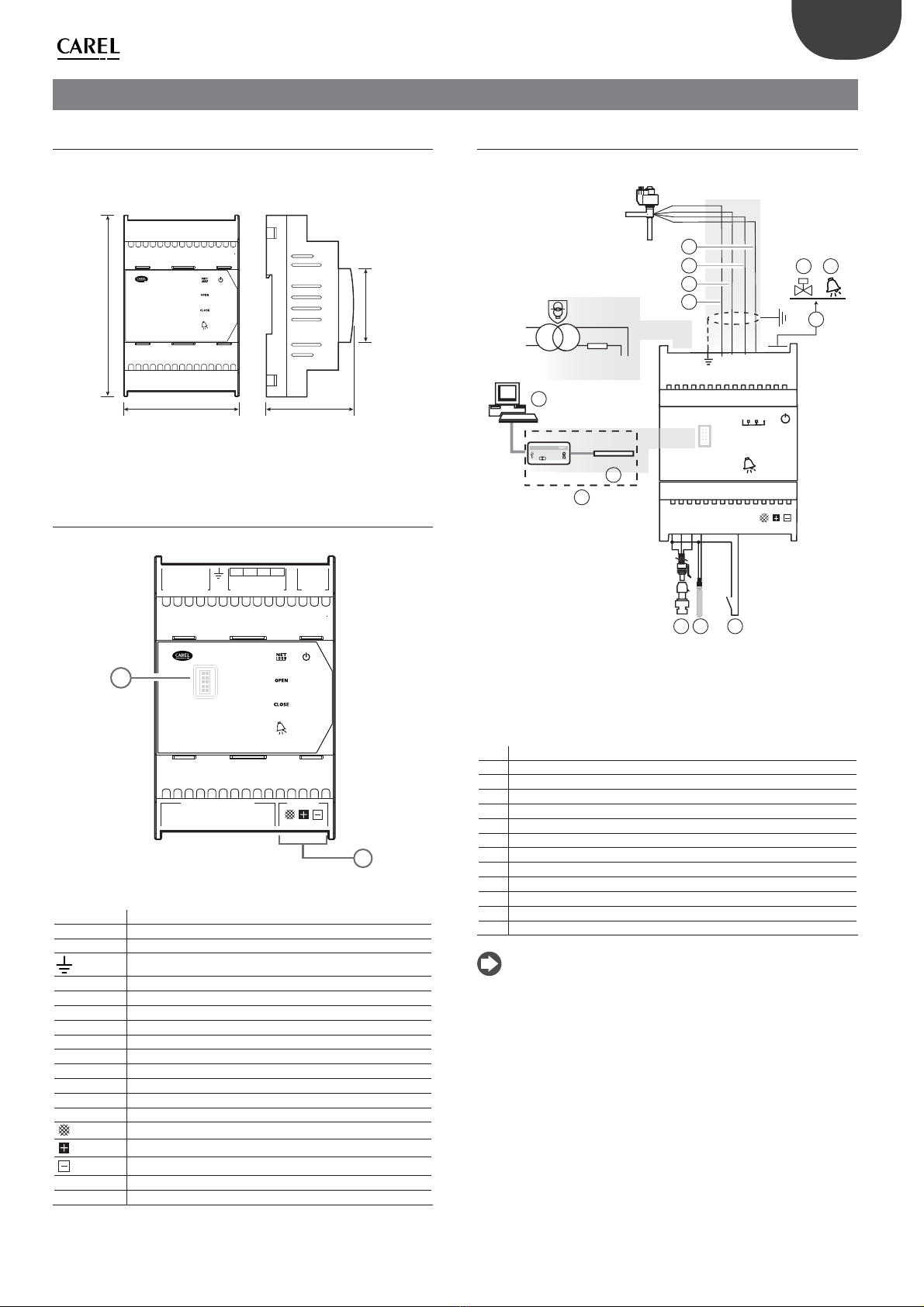
• electrical connections by plug-in screw terminals;
• serial card incorporated in the driver, based on the model (tLAN, pLAN,
RS485/Modbus®);
• compatibility with various types of valves (“universal”models only) and
refrigerants;
• activation/deactivation of control via digital input 1 or remote control
via pLAN, from pCO programmable controller;
• superheat control with protection functions for low superheat, MOP,
LOP, high condensing temperature;
• adaptive superheat control;
• function to optimise superheat control for air-conditioning units
tted with Emerson Climate Digital Scroll™ compressor. In this case,
EVD Evolution must be connected to a CAREL pCO series controller
running an application program that can manage units with Digital
Scroll compressors. This function is only available on the controllers for
CAREL valves;
• conguration and programming by display (accessory), by computer
using the VPM program or by PlantVisor/PlantVisorPro supervisor and
pCO programmable controller;
• commissioning simplied by display with guided procedure for setting
the parameters and checking the electrical connections;
• multi-language graphic display, with “help” function on various
parameters;
• management of dierent units of measure (metric/imperial);
• parameters protected by password, accessible at a service (installer)
and manufacturer level;
• copy the conguration parameters from one driver to another using
the removable display;
• ratiometric or electronic 4 to 20 mA pressure transducer, the latter can
be shared between up to 5 drivers, useful for multiplexed applications;
• possibility to use S3 and S4 as backup probes in the event of faults on
the main probes S1 and S2;
• 4 to 20 mA or 0 to 10 Vdc input to use the driver as a positioner
controlled by an external signal;
• management of power failures with valve closing (only for drivers with
24 Vac power supply and connected to the EVBAT00400 /EVBAT00500
accessory);
• advanced alarm management.

8
ENG
“EVD evolution”+0300005EN - rel. 3.1 - 25.07.2011
For software versions higher than 4.0, the following new functions have
been introduced:
• 24 Vac or 24 Vdc power supply, in the latter case without valve closing
in the event of power failures;
• pre-position time settable by parameter;
• use of digital to start/stop control when there is no communication
with the pCO programmable controller;
• possibility to control the electronic expansion valve in a refrigerant
circuit with SIAM ANB scroll compressor, controlled by CAREL Power+
speed drive (with inverter).
Series of accessories for EVDevolution
Display (code EVDIS00**0)
Easily applicable and removable at any time from the front panel of
the driver, during normal operation displays all the signicant system
variables, the status of the relay output and recognises the activation of
the protection functions and alarms. During commissioning, it guides
the installer in setting the parameters required to start the installation
and, once completed, can copy the parameters to other drivers. The
models dier in the rst settable language, the second language for all
models is English. EVDIS00**0 can be used to congure and monitor all
the control parameters, accessible via password at a service (installer) and
manufacturer level.
Fig. 1.a
USB/tLAN converter (code EVDCNV00E0)
The USB-tLAN converter is connected, once the LED board cover has
been removed, to the service serial port underneath. Fitted with cables
and connectors, it can connect EVD evolution directly to a computer,
which, using the VPM program, can congure and program the driver.
VPM can also be used to update the driver and display rmware.
USB/RS485 converter (code CVSTDUMOR0)
The converter is used to connect the conguration computer and the
EVD evolution controllers, for RS485/Modbus® models only.
Fig. 1.b
Battery module (code EVBAT00400)
Important: the EVBAT00400 battery module can only be used with 24
Vac power supply.
The EVBAT00400 module is an electronic device made by CAREL which
guarantees temporary power supply to the EVD0000E* driver (up to
2 drivers can be connected), in the event of a sudden power failure. It
signals the battery discharged or faulty status via an open collector
output, which can be used by the pCO to generate an alarm message
and notify the technical service for preventive maintenance.
Powered by a 12 V lead backup battery, it supplies 12 Vdc to the
controller for the time required to completely close the electronic valve
being controlled, while during normal operation ensures the battery is
correctly recharged. The battery (code EVBAT00500) and the box (code
EVBATBOX*0) can be purchased separately.
EVBAT00400 EVBAT00500
Fig. 1.c
Valve cable E2VCABS*00 (IP67)
Shielded cable with built-in connector for connection to the valve motor.
The connector code E2VCON0000 (IP65) can also be purchased on its
own, to be wired.
Fig. 1.d

9
ENG
“EVD evolution”+0300005EN - rel. 3.1 - 25.07.2011
2. INSTALLATION
2.1 DIN rail assembly and dimensions
EVD evolution is supplied with screen-printed connectors to simplify
wiring. The shield is connected with a spade terminal.
VBAT
G0
G
EXV connectionPower Suppl
y
Rela
y
NO 1
COM 1
4231
GND
V REF
S1
S2
S3
S4
DI1
DI2
Analog – Digital Input Network
GND Tx/Rx
EVD evolution
70 60
11045
Fig. 2.a
2.2 Description of the terminals
VBAT
G0
G
EXV connection APower Suppl
y
Rela
y
A
NO A
COM A
4231
GND
V REF
S1
S2
S3
S4
DI1
DI2
Analog – Digital Input Network
GND Tx/Rx
EVD evolution
aa
b
Fig. 2.b
Terminal Description
G, G0 Power supply
VBAT Emergency power supply
Functional earth
1,3,2,4 Stepper motor power supply
COM1, NO1 Alarm relay
GND Earth for the signals
VREF Power to active probes
S1 Probe 1 (pressure) or 4 to 20 mA external signal
S2 Probe 2 (temperature) or 0 to 10 V external signal
S3 Probe 3 (pressure)
S4 Probe 4 (temperature)
DI1 Digital input 1
DI2 Digital input 2
Terminal for tLAN, pLAN, RS485, Modbus® connection
Terminal for pLAN, RS485, Modbus® connection
aa service serial port (remove the cover to access )
b serial port
Tab. 2.b
2.3 Connection diagram - superheat control
G
G0
G
G0
VBAT
COMA
NOA
1324
NET
OPEN
CLOSE
Tx/RxGND
DI1
S4
S3
S2
S1
GND
DI2
VREF
2 AT
24 Vac
230 Vac
EVDCNV00E0
20VA(*)
shield
EVD4
PC
EVD4ser vice USB adapter
EEVdriver
4
S
4
2
3
CAREL EXV
1
6
7
8 9 10
11
12 13
5
Fig. 2.c
(*) in combination with Alco EX7 or EX8 valves, use a 35 VA transformer
(code TRADRFE240)
Key:
1 green
2 yellow
3brown
4 white
5 personal computer for conguration
6 USB/tLAN converter
7 adapter
8 ratiometric pressure transducer - evaporation pressure
9 NTC suction temperature
10 digital input 1 congured to enable control
11 free contact (up to 230 Vac)
12 solenoid valve
13 alarm signal
Note:
• connect the valve cable shield to the spade connector;
• the use of the driver for the superheat control requires the use of the
evaporation pressure probe S1 and the suction temperature probe
S2, which will be tted after the evaporator, and digital input 1/2 to
enable control. As an alternative to digital input 1/2, control can be
enabled via remote signal (tLAN, pLAN, RS485). For the positioning of
the probes relating to other applications, see the chapter on“Control”;
• inputs S1, S2 are programmable and the connection to the terminals
depends on the setting of the parameters. See the chapters on
“Commissioning”and “Functions”;
• pressure probe S1 in the diagram is ratiometric. See the general
connection diagram for the other electronic probes, 4 to 20 mA or
combined;
• four probes are needed for superheat control with SIAM ANB
compressors, two to measure the superheat and two to measure the
discharge superheat and the discharge temperature. See chap. 5.

10
ENG
“EVD evolution”+0300005EN - rel. 3.1 - 25.07.2011
2.4 Installation
For installation proceed as follows, with reference to the wiring diagrams:
1. connecttheprobes:theprobescanbeinstalledamaximumdistanceof
10 metres away from the driver, or a maximum of 30 metres as long
as shielded cables are used with minimum cross-section of 1 mm
(connect all the shields to the earth spade connector );
2. connect any digital inputs, maximum length 30 m;
3. connectthepowercabletothevalvemotors:use4-wireshieldedcable
AWG 22 Lmax=10 m or AWG 14 Lmax=50m; failure to connect the
valve motors after connecting the driver will generate the“EEV motor
error”alarm: see paragraph 9.5;
4. carefullyevaluatethemaximumcapacityoftherelayoutputspeciedin
the chapter“Technical specications”;
5. if necessary use a class 2 safety transformer, suitably protected against
short-circuits and voltage surges. For the power ratings see the
general connection diagram and the technical specications.
6. the minimum size of the connection cables must be 0.5 mm2
7. power up the driver in the event of 24Vdc power supply the drive will
close the valve.
Important: in the event of 24Vdc power supply set the“Power supply
mode”parameter=1 to start control. See par. 6.1.
8. program the driver, if necessary: see the chapter“User interface”;
9. connecttheserialnetwork,iffeatured:followtothediagramsbelowfor
the earth connection.
Case 1: multiple drivers connected in a network powered by the same
transformer. Typical application for a series of drivers inside the same
electrical panel.
G
G0
VBAT
COMA
NOA
1
3
2
4
G
G0
VBAT
COMA
NOA
1
3
2
4
2AT
G
G0
VBAT
COMA
NOA
1
3
2
4
2AT
2AT
230 Vac
24 Vac
pCO
Fig. 2.d
Case 2: multiple drivers connected in a network powered by dierent
transformers (G0 not connected to earth). Typical application for a series
of drivers in dierent electrical panels.
G
G0
VBAT
COMA
NOA
1
3
2
4
G
G0
VBAT
COMA
NOA
1
3
2
4
G
G0
VBAT
COMA
NOA
1
3
2
4
2AT
230 Vac
24 Vac
2AT
230 Vac
24 Vac
2AT
230 Vac
24 Vac
pCO
Fig. 2.e
Case 3: multiple drivers connected in a network powered by dierent
transformers with just one earth point. Typical application for a series of
drivers in dierent electrical panels.
G
G0
VBAT
COMA
NOA
1
3
2
4
G
G0
VBAT
COMA
NOA
1
3
2
4
G
G0
VBAT
COMA
NOA
1
3
2
4
2AT
230 Vac
24 Vac
2AT
230 Vac
24 Vac
2AT
230 Vac
24 Vac
pCO
Fig. 2.f
Important: avoid installing the driver in environments with the
following characteristics:
• relative humidity greater than the 90% or condensing;
• strong vibrations or knocks;
• exposure to continuous water sprays;
• exposure to aggressive and polluting atmospheres (e.g.: sulphur
and ammonia fumes, saline mist, smoke) to avoid corrosion and/or
oxidation;
• strong magnetic and/or radio frequency interference (avoid installing
the appliances near transmitting antennae);
• exposure of the driver to direct sunlight and to the elements in general.
Important: When connecting the driver, the following warnings
must be observed:
• if the driver is used in a way not specied in this manual, the level of
protection is not guaranteed.
• do not operate the controller for extended periods without connecting
the valve;
• incorrect connection to the power supply may seriously damage the
driver;
• use cable ends suitable for the corresponding terminals. Loosen each
screw and insert the cable ends, then tighten the screws and lightly
tug the cables to check correct tightness;
• separate as much as possible (at least 3 cm) the probe and digital
input cables from the power cables to the loads so as to avoid possible
electromagnetic disturbance. Never lay power cables and probe cables
in the same conduits (including those in the electrical panels);
• install the shielded valve motor cables in the probe conduits: use
shielded valve motor cables to avoid electromagnetic disturbance to
the probe cables;
• avoid installing the probe cables in the immediate vicinity of power
devices (contactors, circuit breakers, etc.). Reduce the path of the
probe cables as much as possible and avoid enclosing power devices;
• avoid powering the driver directly from the main power supply in the
panel if this supplies dierent devices, such as contactors, solenoid
valves, etc., which will require a separate transformer.
2.5 Valve operation in parallel and
complementary mode
EVD evolution can control two CAREL valves connected together
(see paragraph 4.2), in parallel mode, with identical behaviour, or in
complementary mode, whereby if one valve opens, the other closes by
the same percentage. To achieve such behaviour, simply set the “valve”
parameter (“Two EXV connected together”) and connect the valve motor
power supply wires to the same connector. In the example shown below,
for operation of valve B_2 with valve B_1 in complementary mode simply
swap the connection of wires 1 and 3.
2 CAREL valves connected in parallel
mode
2 CAREL valves connected in com-
plementary mode
1324
4
1
2
3
CAREL EXV
VALVE A_2
CAREL EXV
VALVE A_1
4
1
2
3
1324
4
1
2
3
CAREL EXV
VALVE B_2
CAREL EXV
VALVE B_1
4
3
2
1

11
ENG
“EVD evolution”+0300005EN - rel. 3.1 - 25.07.2011
Note: operation in parallel and complementary mode can only be
used for CAREL valves, within the limits shown in the table below, where
OK means that the valve can be used with all refrigerants at the rated
operating pressure.
Model of CAREL valve
E2V* E3V* E4V* E5V* E6V* E7V*
Two EXV connected
together
OK OK E4V85 with all refrigerants except
for R410A
E4V95 only with R134a
NO NO NO
2.6 Shared pressure probe
Only 4 to 20 mA pressure probes (not ratiometric) can be shared. The
probe can be shared by a maximum of 5 drivers. For multiplexed systems
where controllers EVD evolution1 to EVD evolution5 share the same
pressure probe, choose the normal option for EVD evolution1 and the
“remote”option for the other drivers, up to the fth. EVD evolution6 must
use another pressure probe P2.
EXAMPLE
EVD Evolution1 to EVD Evolution5 EVD Evolution6
Probe S1 -0.5 to 7 barg (P1) to remote, -0.5 to 7 barg -0.5 to 7 barg (P2)
Tx/RxGND
DI1
S4
S3
S2
S1
GND
DI2
VREF
EVD Evolution 1 EVD Evolution 5 EVD Evolution 6
P1 P2
Tx/RxGND
DI1
S4
S3
S2
S1
GND
DI2
VREF
Tx/RxGND
DI1
S4
S3
S2
S1
GND
DI2
VREF
Key: P1 Shared pressure probe
P2 Pressure probe
2.7 Connecting the USB-tLAN converter
Procedure:
• remove the LED board cover by pressing on the fastening points;
• plug the adapter into the service serial port;
• connect the adapter to the converter and then this in turn to the
computer.
• power up the driver.
press
press
OPEN
CLOSE
EVD
evolution
Fig. 2.g
G
G0
VBAT
COMA
NOA
1324
NET
OPEN
CLOSE
Tx/RxGND
DI1
S4
S3
S2
S1
GND
DI2
VREF
EVD4
PC
EVD4ser viceUSBadapter
4
3
2
41
EVDCNV00E0
Fig. 2.h
Key:
1 service serial port
2 adapter
3 USB/tLAN converter
4 personal computer
Note: when using the service serial port connection, the VPM
program can be used to congure the driver and update the driver
and display rmware, downloadable from http://ksa.carel.com.
See the appendix.
2.8 Connecting the USB/RS485 converter
Only on EVD evolution RS485/Modbus® models can the conguration
computer be connected using the USB/RS485 converter and the serial
port, according to the following diagram.
G
G0
VBAT
COMA
NOA
1324
NET
Tx/RxGND
DI1
S4
S3
S2
S1
GND
DI2
VREF
shield2
Analog -Digital Input Network
OPEN
CLOSE
EVD evolution
1
Fig. 2.i
Key: 1 personal computer for conguration
2 USB/RS485 converter
Note:
• the serial port can be used for conguration with the VPM program and
for updating the driver rmware, downloadable from http://ksa.carel.com;
• to save time, up to 8 EVD evolution drivers can be connected to the
computer, updating the rmware at the same time (each driver must
have a dierent network address).
2.9 Upload,Downloadand Resetparameters
(display)
Procedure:
10. press the Help and Enter buttons together for 5 seconds;
11. a multiple choice menu will be displayed, use UP/DOWN to select the
required procedure;
12. conrm by pressing ENTER;
13. the display will prompt for conrmation, press ENTER;
14. at the end a message will be shown to notify the operation if the
operation was successful.
• UPLOAD: the display saves all the values of the parameters on the
source driver;
• DOWNLOAD: the display copies all the values of the parameters to the
target driver;
• RESET: all the parameters on the driver are restored to the default
values. See the table of parameters in chapter 8.
JEAD699DLCAD69G:H:IFig. 2.j
Important:
• the procedure must be carried out with driver powered;
• DO NOT remove the display from the driver during the UPLOAD,
DOWNLOAD, RESET procedure;
• the parameters cannot be downloaded if the source driver and the
target driver have incompatible rmware.

12
ENG
“EVD evolution”+0300005EN - rel. 3.1 - 25.07.2011
2.10 Show electrical connections (display)
To display the probe and valve electrical connections for drivers A and B,
enter display mode. See paragraph 3.4.
2.11 General connection diagram
EVD evolution
G
G0
VBAT
COMA
NOA
1324
Tx/Rx
GND
DI1
S4
S3
S2
S1
GND
DI2
VREF
Tx/Rx
GND
DI1
S4
S3
S2
S1
GND
DI2
VREF
G
G0
VBAT
COMA
NOA
shield
shield
shield
shield
1
3
2
4
Sporlan
SEI / SEH / SER
DANFOSS
ETS
ALCO
EX5/6
EX7/8
EVD4
PC
EVD4service USB adapter
EEVdriver
4
Tx/Rx
GND
pCO
GNDGND
pCO
S
4
4
4 4
2
3
3
1
1
14
1
5
7
8
B C
D
E F G
H
910
11
12
13
15
15 15
16
14 14
EVD0000E0*: tLAN version
EVD0000E1*: pLAN version
EVD0000E2*: RS485 version
2
3
Tx/Rx
GND
DI1
S4
S3
S2
S1
GND
DI2
VREF
Tx/Rx
GND
DI1
S4
S3
S2
S1
GND
DI2
VREF
1
15
17
14
4
Tx/Rx
GND
DI1
S4
S3
S2
S1
GND
DI2
VREF
Tx/Rx
GND
DI1
S4
S3
S2
S1
GND
DI2
VREF
4
15
3
with batterywithout battery
battery discharged of fault signal
CAREL EXV
RS485
Modbus®
CVSTDUM0R0
pCO
EVDCNV00E0
6
G
G0
2 AT
24 Vac
230 Vac
20 VA (*)
G
G0
VBAT
Battery module
GND
BAT ERR
-
+
EVD
G
G0
VBAT
EVBAT00500
35 VA
EVBAT00400
4 AT
24 Vac
230 Vac
2 AT
TRADRFE240
G
2 AT
G0
Fig. 2.k
(*): in combination with Alco EX7 or EX8 valves, use a 35 VA transformer
code TRADRFE240.
Key:
1 green A Connection to EVBAT200/300
2 yellow B Connection to electronic pressure probe (SPK**0000) or piezoresistive pressure
transducer (SPKT00**C0)
3brown
4 white C Connection as positioner (4 to 20 mA input)
5 conguration computer D Connection as positioner (0 to 10 Vdc input)
6 USB/tLAN converter E Connection to combined pressure/temperature probe (SPKP00**T0)
7 adapter
8 ratiometric pressure transducer F Connection to backup probes (S3, S4)
9 NTC probe G Ratiometric pressure transducer connections (SPKT00**R0)
10 digital input 1 congured to enable control H Connections o other types of valves
11 free contact (up to 230 Vac) 1The maximum length of the connection cable to the EVBAT400/500 module is 5 m.
12 solenoid valve
13 alarm signal 2The connection cable to the valve motor must be 4-wire shielded, AWG 18/22
Lmax= 10 m
14 red
15 black 3Connect all the shields of the probe cables to the earth spade.
16 blue
17 conguration/supervision computer
18 digital input 2 congured to signal discharged battery
Note: for the conguration of the digital inputs see par. 6.3.

13
ENG
“EVD evolution”+0300005EN - rel. 3.1 - 25.07.2011
3. USER INTERFACE
The user interface consists of 5 LEDs that display the operating status, as
shown in the table:
EVD evolution
Fig. 3.a
Key:
LED ON OFF Flashing
NET Connection available No connection Communication
error
OPEN Opening valve - Driver disabled (*)
CLOSE Closing valve - Driver disabled (*)
Active alarm - -
Driver powered Driver not powered Wrong power supply
(see chap. Alarms)
Tab. 3.a
(*) Awaiting completion of the initial conguration
3.1 Assemblingthedisplayboard(accessory)
The display board, once installed, is used to perform all the conguration
and programming operations on the driver. It displays the operating
status, the signicant values for the type of control that the driver
is performing (e.g. superheat control), the alarms, the status of the
digital inputs and the relay output. Finally, it can save the conguration
parameters for one driver and transfer them to a second driver (see the
procedure for upload and download parameters).
For installation:
• remove the cover, pressing on the fastening points;
• t the display board, as shown;
• the display will come on, and if the driver is being commissioned, the
guided conguration procedure will start.
press
press
Fig. 3.b
Important: the driver is not activated if the conguration procedure
has not been completed.
The front panel now holds the display and the keypad, made up of 6
buttons that, pressed alone or in combination, are used to perform all the
conguration and programming operations on the driver.
3.2 Display and keypad
The graphic display shows 2 system variables, the control status of the
driver, the activation of the protectors, any alarms and the status of the
relay output. Hjgg^hXVaYVb#)#.@6eZgijgVkVakdaV))DCBDE6A6GB""GZaZ1
7
2
3
4
5
6
IFig. 3.c
Key:
1 1st variable displayed
2 2nd variable displayed
3 relay status
4 alarm (press“HELP”)
5 protector activated
6control status
7 adaptive control in progress
Display writings
Control status Protection active
ON Operation LowSH Low superheat
OFF Standby LOP Low evaporation tempe-
rature
POS Positioning MOP High evaporation tempe-
rature
WAIT Wait High
Tcond
High condensing tempe-
rature
CLOSE Closing
INIT Valve motor error reco-
gnition procedure (*)
TUN Tuning in progress
Tab. 3.b
(*) The valve motor error recognition procedure can be disabled. See
paragraph 9.5
Keypad
Button Function
Prg opens the screen for entering the password to access program-
ming mode.
• if in alarm status, displays the alarm queue;
• in the “Manufacturer” level, when scrolling the parameters, shows
the explanation screens (Help).
Esc • exits the Programming (Service/Manufacturer) and Display
modes;
• after setting a parameter, exits without saving the changes.
UP/
DOWN
• navigates the display screens;
• increases/decreases the value.
Enter
• switches from the display to parameter programming mode;
• conrms the value and returns to the list of parameters.
Tab. 3.c
Note: the variables displayed as standard can be selected by
conguring the parameters “Display main var. 1”and “Display main var. 2”
accordingly. See the list of parameters.

14
ENG
“EVD evolution”+0300005EN - rel. 3.1 - 25.07.2011
3.3 Display mode (display)
Display mode is used to display the useful variables showing the
operation of the system.
The variables displayed depend on the type of control selected.
1. press Esc one or more times to switch to the standard display;
2. press UP/DOWN: the display shows a graph of the superheat, the
percentage of valve opening, the evaporation pressure and
temperature and the suction temperature variables;
3. pressUP/DOWN:thevariablesareshownonthedisplay,followedbythe
screens with the probe and valve motor electrical connections;
4. press Esc to exit display mode.
For the complete list of the variables shown on the display, see the
chapter: “Table of parameters”. H=2)#.@+#)8(#-WVg\&#*8'&&hie+.Fig. 3.d
3.4 Programming mode (display)
The parameters can be modied using the front keypad. Access diers
according to the user level: Service (Installer) and manufacturer.
Modifying the Service parameters
IThe Service parameters, as well as the parameters for commissioning
the driver, also include those for the conguration of the inputs, the relay
output, the superheat set point or the type of control in general, and the
protection thresholds. See the table of parameters.
Procedure:
5. press Esc one or more times to switch to the standard display;
6. press Prg: the display shows a screen with the PASSWORD request;
7. press ENTER and enter the password for the Service level: 22, starting
from the right-most gure and conrming each gure with ENTER;
8. ifthevalueenterediscorrect,therstmodiableparameterisdisplayed,
network address;
9. press UP/DOWN to select the parameter to be set;
10. press ENTER to move to the value of the parameter;
11. press UP/DOWN to modify the value;
12. press ENTER to save the new value of the parameter;
13. repeat steps 5, 6, 7, 8 to modify the other parameters;
14. press Esc to exit the procedure for modifying the Service parameters.
E6HHLDG9%%%&Fig. 3.e
Note:
• if when setting a parameter the value entered is out-of-range, this is
not accepted and the parameter soon after returns to the previous
value;
• if no button is pressed, after 5 min the display automatically returns to
the standard mode;
• to set a negative value move to the left-most digit and press Up/Down.
Modifying the Manufacturer parameters
The Manufacturer level is used to congure all the driver parameters,
and consequently, in addition to the Service parameters, the parameters
relating to alarm management, the probes and the conguration of the
valve. See the table of parameters.
Procedure:
15. press Esc one or more times to switch to the standard display;
16. press Prg : the display shows a screen with the PASSWORD request;
17. pressENTERandentertheManufacturerlevelpassword:66,startingfrom
the right-most gure and conrming each gure with ENTER;
18. if the value entered is correct, the list of parameter categories is shown:
- Conguration
- Probes
- Control
- Special
- Alarm conguration
- Valve
19. presstheUP/DOWNbuttonstoselectthecategoryandENTERtoaccess
the rst parameter in the category;
20. pressUP/DOWNtoselecttheparametertobesetandENTERtomoveto
the value of the parameter;
21. press UP/DOWN to modify the value;
22. press ENTER to save the new value of the parameter;
23. repeat steps 6, 7, 8 to modify the other parameters;
24. press Esc to exit the procedure for modifying the Manufacturer
parameters. 8DC;><JG6I>DCEGD7:H8DCIGDAHE:8>6A6A6GB8DC;><JG6I>DCK6AK:Fig. 3.f
Note:
• all the driver parameters can be modied by entering the Manufacturer
level;
• if when setting a parameter the value entered is out-of-range, this is
not accepted and the parameter soon after returns to the previous
value;
• if no button is pressed, after 5 min the display automatically returns to
the standard mode.

15
ENG
“EVD evolution”+0300005EN - rel. 3.1 - 25.07.2011
4. COMMISSIONING
4.1 Commissioning
Once the electrical connections have been completed (see the chapter
on installation) and the power supply has been connected, the operations
required for commissioning the driver depend on the type of interface
used, however essentially involve setting just 4 parameters: refrigerant,
valve, type of pressure probe S1 and type of main control.
Types of interfaces:
• DISPLAY: after having correctly congured the setup parameters,
conrmation will be requested. Only after conrmation will the driver
be enabled for operation, the main screen will be shown on the display
and control will be able to commence when requested by the pCO
controller via LAN or when digital input DI1/DI2 closes. See paragraph
4.2;
• VPM: to enable control of the driver via VPM, set “Enable EVD control”
to 1; this is included in the safety parameters, in the special parameters
menu, under the corresponding access level. However, the setup
parameters should rst be set in the related menu. The driver will then
be enabled for operation and control will be able to commence when
requested by the pCO controller via LAN or when digital input DI1/
DI2 closes. If due to error or for any other reason “Enable EVD control”
should be set to 0 (zero), the driver will immediately stop control and
will remain in standby until re-enabled, with the valve stopped in the
last position;
• SUPERVISOR: to simplify the commissioning of a considerable number
of drivers using the supervisor, the setup operation on the display can
be limited to simply setting the network address. The display will then
be able to be removed and the conguration procedure postponed to a
laterstageusingthesupervisor or,ifnecessary,reconnecting the display.
To enable control of the driver via supervisor, set“Enable EVD control”;
thisis included in thesafetyparameters,in the special parametersmenu,
under the corresponding access level. However, the setup parameters
should rst be set in the related menu. The driver will then be enabled
for operation and control will be able to commence when requested
by the pCO controller via pLAN or when digital input DI1/DI2 closes.
As highlighted on the supervisor, inside of the yellow information eld
relating to the “Enable EVD control” parameter, if due to error or for
any other reason “Enable EVD control” should be set to 0 (zero), the
driver will immediately stop control and will remain in standby until
re-enabled, with the valve stopped in the last position;
• pCO PROGRAMMABLE CONTROLLER: the rst operation to be
performed, if necessary, is to set the network address using the display.
If a pLAN, tLAN or Modbus® driver is used, connected to a pCO family
controller, the setup parameters will not need to be set and conrmed.
In fact, the application running on the pCO will manage the correct
values based on the unit controlled. Consequently, simply set the pLAN,
tLAN or Modbus® address for the driver as required by the application
on the pCO, and after a few seconds communication will commence
between the two instruments and the driver automatically be enabled
for control. The main screen will shown on the display, which can then
be removed, and control will be able to commence when requested
by the pCO controller or digital input DI1/DI2.
If there is no communication between the pCO and the driver (see the
paragraph “LAN error alarm”), the driver will be able to continue control
based on the status of digital input DI1/DI2. See par. 6.3.
4.2 Guided commissioning procedure
(display)
After having tted the display:
8dc[^\jgi^dc&$(CZildg`VYYgZhh&.-8dc[^\jgi^dc&$(CZildg`VYYgZhh&.-the rst parameter is displayed:
network address;
press Enter to move to the
value of the parameter
press UP/DOWN to modify the
value
8dc[^\jgi^dc&$(CZildg`VYYgZhh&press Enter to conrm the value press UP/DOWN to move to the
next parameter, refrigerant
repeat steps 2, 3, 4, 5 to modify the values of the parameters:
refrigerant, valve, pressure probe S1, main regulation;
G
G0
VBAT
COM1
NO1
1
3
2
4
yellow
white
brown
green
TxRx
GND
DI1
S4
S3
S2
S1
GND
DI2
VREF
white
black
green
TEMP S2
PRESS S1
check that the electrical connections are correct;
8dc[^\jgi^dc:cYXdc[^\jgVi^dc4N:HCDif the conguration is correct
exit the procedure, otherwise
choose NO and return to step 2;
At the end of the conguration procedure the controller activates the
valve motor error recognition procedure, showing “INIT” on the display.
See paragraph 9.5
To simplify commissioning and avoid possible malfunctions, the driver
will not start until the following have been congured:
1. network address;
2. refrigerant;
3. valve;
4. pressure probe S1;
5. type of main control, that is, the type of unit the superheat control is
applied to.
Note:
• to exit the guided commissioning procedure press the DOWN button
repeatedly and nally conrm that conguration has been completed.
The guided procedure CANNOT be ended by pressing Esc;
• if the conguration procedure ends with a conguration error, access
Service parameter programming mode and modify the value of the
parameter in question;
• if the valve and/or the pressure probe used are not available in the
list, select any model and end the procedure. Then the driver will
be enabled for control, and it will be possible to enter Manufacturer
programming mode and set the corresponding parameters manually.
Important: for 24 Vdc power supply, at the end of the guided
commissioning procedure, to start control set “Power supply mode”
parameter=1, otherwise the valve remains in the closed position. See
paragraph 6.1.

16
ENG
“EVD evolution”+0300005EN - rel. 3.1 - 25.07.2011
Network address
The network address assigns to the driver an address for the serial
connection to a supervisory system via RS485, and to a pCO controller via
pLAN, tLAN, Modbus®.
Parameter/description Def. Min. Max. UOM
CONFIGURATION
Network address 198 1 207 -
Tab. 4.d
For network connection of the RS485/Modbus® models the
communication speed also needs to be set, in bits per second, using the
parameter“Network settings”. See paragraph 6.1.
Refrigerant
The type of refrigerant is essential for calculating the superheat. In
addition, it is used to calculate the evaporation and condensing
temperature based on the reading of the pressure probe.
Parameter/description Def.
CONFIGURATION
Refrigerant:
1= R22; 2= R134a; 3= R404A; 4= R407C; 5= R410A;6= R507A;
7= R290; 8= R600; 9= R600a; 10= R717; 11= R744; 12= R728;
13= R1270; 14= R417A; 15= R422D; 16= R413A; 17= R422A; 18=
R423A; 19= R407A; 20= R427A; 21=R245Fa; 22=R407F
R404A
Tab. 4.e
Valve
Setting the type of valve automatically denes all the control parameters
based on the manufacturer’s data for each model.
In Manufacturer programming mode, the control parameters can then
be fully customised if the valve used is not in the standard list. In this case,
the driver will detect the modication and indicate the type of valve as
“Customised”.
Parameter/description Def.
CONFIGURATION
Valve:
1= CAREL EXV;
2= Alco EX4; 3= Alco EX5; 4= Alco EX6; 5= Alco EX7; 6= Alco EX8
330Hz suggested by CAREL; 7= Alco EX8 500Hz specied by Alco; 8=
Sporlan SEI 0.5-11; 9= Sporlan SER 1.5-20; 10= Sporlan SEI 30; 11=
Sporlan SEI 50; 12= Sporlan SEH 100; 13= Sporlan SEH 175; 14=
Danfoss ETS 12.5-25B; 15= Danfoss ETS 50B; 16= Danfoss ETS 100B;
17= Danfoss ETS 250; 18= Danfoss ETS 400; 19= two CAREL ExV
connected together 20= Sporlan Ser(I)G, J, K.; 21= Danfoss CCM
10-20-30; 22= Danfoss CCM 40
CAREL
EXV
Tab. 4.f
Important:
• two CAREL EXV valves connected together must be selected if two
CAREL EXV valves are connected to the same terminal, to have parallel
or complementary operation;
• as described, control is only possible with CAREL EXV valves;
• not all CAREL valves can be connected: see paragraph 2.5.
Pressure probe S1
Setting the type of pressure probe S1 denes the range of measurement
and the alarm limits based on the manufacturer’s data for each model,
usually indicated on the rating plate on the probe.
Parameter/description Def.
CONFIGURATION
Sensor S1 Ratiom.:
-1 to 9.3
barg
Ratiometric (OUT=0 to 5V) Electronic (OUT=4 to 20mA)
1= -1 to 4.2 barg 8= -0.5 to 7 barg
2= 0.4 to 9.3 barg 9= 0 to 10 barg
3= -1 to 9.3 barg 10= 0 to 18,2 barg
4= 0 to 17.3 barg 11= 0 to 25 barg
5= 0.85 to 34.2 barg 12= 0 to 30 barg
6= 0 to 34.5 barg 13= 0 to 44.8 barg
7= 0 to 45 barg 14= remote, -0.5 to 7 barg
15= remote, 0 to 10 barg
16= remote, 0 to 18,2 barg
17= remote, 0 to 25 barg
18= remote, 0 to 30 barg
19= remote, 0 to 44.8 barg
20= external signal (4 to 20 mA)
21= -1 to 12.8 barg
22= 0 to 20.7 barg
23= 1.86 to 43.0 barg
Tab. 4.g
Important: in case two pressure probes are installed S1 and S3,
they must be of the same type. It is not allowed to use a ratiometric probe
and an electronic one.
Note: in the case of multiplexed systems where the same pressure
probe is shared between multiple drivers, choose the normal option for
the rst driver and the“remote”option for the remaining drivers.The same
pressure transducer can be shared between a maximum of 5 drivers.
Example: to use the same pressure probe, -0.5 to 7 bars, for 3 drivers
For the rst driver, select: -0.5 to 7 barg
For the second and third driver select: remote -0.5 to 7 barg.
See paragraph 2.6
Note:
• the range of measurement by default is always in bar gauge (barg).In
the manufacturer menu, the parameters corresponding to the range
of measurement and the alarms can be customised if the probe used
is not in the standard list. If modifying the range of measurement, the
driver will detect the modication and indicate the type of probe S1
as“Customised”.
• The software on the driver takes into consideration the unit of measure.
If a range of measurement is selected and then the unit of measure is
changed (from bars to psi), the driver automatically updates in limits
of the range of measurement and the alarm limits.BY default, the main
control probe S2 is set as “CAREL NTC”. Other types of probes can be
selected in the service menu.
• Unlike the pressure probes, the temperature probes do not have any
modiable parameters relating to the range of measurement, and
consequently only the models indicated in the list can be used (see
the chapter on “Functions” and the list of parameters). In any case,
in manufacturer programming mode, the limits for the probe alarm
signal can be customised.

17
ENG
“EVD evolution”+0300005EN - rel. 3.1 - 25.07.2011
Main regulation
Setting the main control denes the operating mode of the driver.
Parameter/description Def.
CONFIGURATION
Main control multiplexed
cabinet/cold
room
Superheat control
1= multiplexed cabinet/cold room
2= cabinet/cold room with on-board compressor
3=“perturbed” cabinet/cold room
4= cabinet/cold room with subcritical CO2
5= R404A condenser for subcritical CO2
6= air-conditioner/chiller with plate heat exchanger
7= air-conditioner/chiller with tube bundle heat exchanger
8= air-conditioner/chiller with nned coil heat exchanger
9= air-conditioner/chiller with variable cooling capacity
10=“perturbed” air-conditioner/chiller
Advanced control
11= EPR back pressure
12= hot gas bypass by pressure
13= hot gas bypass by temperature
14= transcritical CO2tgas cooler
15= analogue positioner (4 to 20 mA)
16= analogue positioner (0 to 10 V)
17= air-conditioner/chiller or cabinet/cold room with
adaptive control
18= air-conditioner/chiller with digital scroll compressor
19= AC/chiller with SIAM ANB scroll compressor(*)
20= superheat regulation with 2 temperature probes
21= I/O expander for pCO
Tab. 4.h
(*) CAREL valve drivers only
The superheat set point and all the parameters corresponding to PID
control, the operation of the protectors and the meaning and use of
probes S1 and/or S2 will be automatically set to the values recommended
by CAREL based on the selected application.
During this initial conguration phase, only superheat control mode
from 1 to 10 can be set, which dier based on the application (chiller,
refrigerated cabinet, etc.).
In the event of errors in the initial conguration, these parameters can
later be accessed and modied inside the service or manufacturer menu.
If the driver default parameters are restored (RESET procedure, see the
chapter on Installation), when next started the display will again show
the guided commissioning procedure.
4.3 Checks after commissioning
After commissioning:
• check that the valve completes a full closing cycle to perform
alignment;
• set, if necessary, in Service or Manufacturer programming mode, the
superheat set point (otherwise keep the value recommended by
CAREL based on the application) and the protection thresholds (LOP,
MOP, etc.). See the chapter on Protectors.
4.4 Other functions
By entering Service programming mode, other types of main control
can be selected (transcritical CO2, hot gas bypass, etc.), as well as so-
called advanced control functions, which do not involve the superheat,
activating auxiliary controls that use probes S3 and/or S4 and setting the
suitable values for the control set point and the LowSH, LOP and MOP
protection thresholds (see the chapter on“Protectors”), which depend on
the specic characteristics of the unit controlled.
By entering Manufacturer programming mode, nally, the operation of
the driver can be completely customised, setting the function of each
parameter. If the parameters corresponding to PID control are modied,
the driver will detect the modication and indicate the main control as
“Customised”.

18
ENG
“EVD evolution”+0300005EN - rel. 3.1 - 25.07.2011
5. CONTROL
5.2 Superheat control
The primary purpose of the electronic valve is ensure that the ow-rate
of refrigerant that ows through the nozzle corresponds to the ow-rate
required by the compressor. In this way, the evaporation process will take
place along the entire length of the evaporator and there will be no liquid
at the outlet and consequently in the branch that runs to the compressor.
As liquid is not compressible, it may cause damage to the compressor
and even breakage if the quantity is considerable and the situation lasts
some time.
Superheat control
The parameter that the control of the electronic valve is based on is the
superheat temperature, which eectively tells whether or not there is
liquid at the end of the evaporator.
The superheat temperature is calculated as the dierence between:
superheated gas temperature (measured by a temperature probe located
at the end of the evaporator) and the saturated evaporation temperature
(calculated based on the reading of a pressure transducer located at the
end of the evaporator and using the Tsat(P) conversion curve for each
refrigerant).
Superheat= Superheated gas temperature(*) – Saturated evaporation
temperature
(*) suction
If the superheat temperature is high it means that the evaporation
process is completed well before the end of the evaporator, and therefore
ow-rate of refrigerant through the valve is insucient. This causes a
reduction in cooling eciency due to the failure to exploit part of the
evaporator. The valve must therefore be opened further.
Vice-versa, if the superheat temperature is low it means that the
evaporation process has not concluded at the end of the evaporator
and a certain quantity of liquid will still be present at the inlet to the
compressor. The valve must therefore be closed further. The operating
range of the superheat temperature is limited at the lower end: if the
ow-rate through the valve is excessive the superheat measured will be
near 0 K. This indicates the presence of liquid, even if the percentage
of this relative to the gas cannot be quantied. There is therefore un
undetermined risk to the compressor that must be avoided. Moreover, a
high superheat temperature as mentioned corresponds to an insucient
ow-rate of refrigerant.
The superheat temperature must therefore always be greater than 0 K
and have a minimum stable value allowed by the valve-unit system. A
low superheat temperature in fact corresponds to a situation of probable
instability due to the turbulent evaporation process approaching the
measurement point of the probes. The expansion valve must therefore
be controlled with extreme precision and a reaction capacity around
the superheat set point, which will almost always vary from 3 to 14 K.
Set point values outside of this range are quite infrequent and relate to
special applications.
S2
S1
EVD
evolution
P
E
V
S
F
L
M
T
CP
C
EEV
Fig. 5.a
5.1 Main and auxiliary control
EVD evolution features two types of control
• main;
• auxiliary.
Main control is always active, while auxiliary control can be activated
by parameter. Main control denes the operating mode of the driver.
The rst 10 settings refer to superheat control, the others are so-called
“special”settings and are pressure or temperature settings or depend on
a control signal from an external controller.
The two last advanced functions also relate to superheat control.
Parameter/description Def.
CONFIGURATION
Main control multiplexed
cabinet/
cold room
Superheat control
1= multiplexed cabinet/cold room
2= cabinet/cold room with on-board compressor
3=“perturbed” cabinet/cold room
4= cabinet/cold room with subcritical CO2
5= R404A condenser for subcritical CO2
6= air-conditioner/chiller with plate heat exchanger
7= air-conditioner/chiller with tube bundle heat exchanger
8= air-conditioner/chiller with nned coil heat exchanger
9= air-conditioner/chiller with variable cooling capacity
10=“perturbed” air-conditioner/chiller
Advanced control
11= EPR back pressure
12= hot gas bypass by pressure
13= hot gas bypass by temperature
14= gas cooler CO2transcritical
15= analogue positioner (4 to 20 mA)
16= analogue positioner (0 to 10 V)
17= air-conditioner/chiller or cabinet/ cold room with adapti-
ve control
18= air-conditioner/chiller with digital scroll compressor
19= AC/chiller with SIAM ANB scroll compressor(*)
20= superheat regulation with 2 temperature probes
21= I/O expander for pCO
Tab. 5.a
(*) only for CAREL valve drivers
Note:
• R404A condensers with subcritical CO2refer to superheat control for
valves installed in cascading systems where the ow of R404A (or other
refrigerant) in an exchanger acting as the CO2condenser needs to be
controlled;
• perturbated cabinet/cold room or air-conditioner/chiller refer to units
that momentarily or permanently operate with swinging condensing
or evaporation pressure.
Auxiliary control features the following settings:
Parameter/description Def.
CONFIGURATION
Auxiliary control Disabled
Disabled
High condensing temperature protection on S3 probe
Modulating thermostat on S4 probe
Backup probes on S3 & S4
Tab. 5.b
Important: the “High condensing temperature protection” and
“Modulating thermostat” auxiliary settings can only be enabled if the
main control is also superheat control with settings 1 to 10 and 17, 18. On
the other hand, the“Backup probes on S3 and S4”auxiliary control can be
activated, once the corresponding probes have been connected, only for
settings from 1 to 18.
The following paragraphs explain all the types of control that can be set
on EVD evolution.

19
ENG
“EVD evolution”+0300005EN - rel. 3.1 - 25.07.2011
Key:
CP compressor EEV electronic expansion valve
C condenser V solenoid valve
L liquid receiver E evaporator
F dewatering lter P pressure probe (transducer)
S liquid indicator T temperature probe
For the wiring, see paragraph 2.7 “General connection diagram”.
Note: superheat control in a refrigerant circuit with SIAM scroll
compressor requires two probes for superheat control and two probes
downstream of the compressor for discharge superheat and discharge
temperature control. See par. 5.5.
PIDparameters
Superheat control, as for any other mode that can be selected with the
“main control” parameter, is performed using PID control, which in its
simplest form is dened by the law:
u(t)= K e(t) + 1∫e(t)dt + Tdde(t)
dtTi
Key:
u(t) Valve position Ti Integration time
e(t) Error Td Derivative time
K Proportional gain
Note that regulation is calculated as the sum of three separate contributions:
proportional, integral and derivative.
• the proportional action opens or closes the valve proportionally to
the variation in the superheat temperature. Thus the greater the K
(proportional gain) the higher the response speed of the valve. The
proportional action does not consider the superheat set point, but
rather only reacts to variations. Therefore if the superheat value does
not vary signicantly, the valve will essentially remain stationary and
the set point cannot be reached;
• the integral action is linked to time and moves the valve in proportion
to the deviation of the superheat value from the set point. The greater
the deviations, the more intense the integral action; in addition, the
lower the value of T (integration time), the more intense the action
will be. The integration time, in summary, represents the intensity of
the reaction of the valve, especially when the superheat value is not
near the set point;
• the derivative action is linked to the speed of variation of the superheat
value, that is, the gradient at which the superheat changes from instant
to instant. It tends to react to any sudden variations, bringing forward
the corrective action, and its intensity depends on the value of the
time Td (derivative time).
Parameter/description Def. Min. Max. UOM
CONTROL
Superheat set point 11 LowSH: t.hold 180 (320) K (°F)
PID proport. gain 15 0 800 -
PID integration time 150 0 1000 s
PID derivative time 5 0 800 s
Tab. 5.c
See the “EEV system guide” +030220810 for further information on
calibrating PID control.
Note: when selecting the type of main control (both superheat
control and special modes), the PID control values suggested by CAREL
will be automatically set for each application.
Protector control parameters
See the chapter on “Protectors”. Note that the protection thresholds are
set by the installer/manufacturer, while the times are automatically set
based on the PID control values suggested by CAREL for each application.
Parameter/description Def. Min. Max. UOM
CONTROL
LowSH protection threshold 5 -40 (-72) superh.
set point.
K(°F)
LowSH protection integration
time
15 0 800 s
LOP protection threshold -50 -60 (-76) MOP th-
reshold
°C(°F)
LOP protection integration time 0 0 800 s
MOP protection threshold 50 LOP thre-
shold
200 (392) °C(°F)
MOP protection integration time 20 0 800 s
ADVANCED
High Tcond threshold 80 -60 (-76) 200 (392) °C (°F)
High Tcond integration time 20 0 800 s
Tab. 5.d
5.3 Adaptive control and autotuning
EVD evolution features two functions used to automatically optimise the
PID parameters for superheat control, useful in applications where there
are frequent variations in thermal load:
1. automatic adaptive control: the function continuously evaluates the
eectiveness of superheat control and activates one or more
optimisation procedures accordingly;
2. manual autotuning: this is activated by the user and involves just one
optimisation procedure.
Both procedures give new values to the PID superheat control and
protection function parameters:
- PID: proportional gain;
- PID: integration time;
- PID: derivative time;
- LowSH: low superheat integration time;
- LOP: low evaporation temperature integration time;
- MOP: high evaporation temperature integration time;
- HiTcond: high condensing temperature integration time.
Given the highly variable dynamics of superheat control on dierent units,
applications and valves, the theories on stability that adaptive control
and autotuning are based on are not always denitive. As a consequence,
the following procedure is suggested, in which each successive step is
performed if the previous has not given a positive outcome:
1) use the parameters recommended by CAREL to control the dierent
units based on the values available for the“Main control”parameter;
2) use any parameters tested and calibrated manually based on laboratory
or eld experiences with the unit in question;
3) enable automatic adaptive control;
4) activate one or more manual autotuning procedures with the unit in
stable operating conditions if adaptive control generates the “Adaptive
control ineective” alarm.
Adaptive control
After having completed the commissioning procedure, to activate
adaptive control, set the parameter:
“Main control”= air-conditioner/chiller or showcase/cold room with
adaptive control.
Parameter/description Def.
CONFIGURATION
Main control
...
air-conditioner/chiller or cabinet/cold
room with adaptive control
multiplexed cabinet/cold room
Tab. 5.e
The activation status of the tuning procedure will be shown on the
standard display by the letter“T”.
Other manuals for EVD evolution
1
This manual suits for next models
14
Table of contents
Other Carel DC Drive manuals
Popular DC Drive manuals by other brands

Danfoss
Danfoss VLT AutomationDrive FC 300 Programming guide

GFA
GFA ELEKTROMAT SI 25.15-30,00 Ex installation instructions

GE
GE AF-650 GP Series Design guide

Danfoss
Danfoss VLT AQUA Drive FC 202 Design guide

GEZE
GEZE E 170 /230 V AC Wiring diagram

CERUS
CERUS Titan P Series Installation, Programming Operation, & Maintenance Manual