Carel Power+ User manual

Integrated Control Solutions & Energy Savings
NO POWER
& SIGNAL
CABLES
TOGETHER
READ CAREFULLY IN THE TEXT!
Power+
User manual
Speed drive


ENG
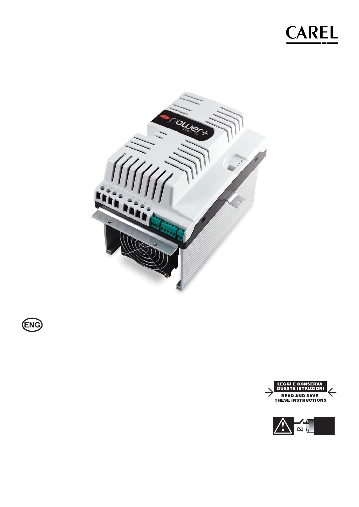
“Power+” +0300050EN - rel. 2.3 - 08.06.20123
WARNINGS
CAREL bases the development of its products on decades of experience
in HVAC, on the continuous investments in technological innovations
to products, procedures and strict quality processes with in-circuit and
functional testing on 100% of its products, and on the most innovative
production technology available on the market. CAREL and its subsidiaries
nonetheless cannot guarantee that all the aspects of the product and the
software included with the product respond to the requirements of the
nal application, despite the product being developed according to start-
of-the-art techniques.
The customer (manufacturer, developer or installer of the nal equipment)
accepts all liability and risk relating to the conguration of the product
in order to reach the expected results in relation to the specic nal
installation and/or equipment.
CAREL may, based on specic agreements, act as a consultant for the
positive commissioning of the nal unit/application, however in no case
does it accept liability for the correct operation of the nal equipment/
system.
The CAREL product is a state-of-the-art product, whose operation is
specied in the technical documentation supplied with the product or
can be downloaded, even prior to purchase, from the website www.CAREL.
com.
Each CAREL product, in relation to its advanced level of technology,
requires setup / conguration / programming / commissioning to be
able to operate in the best possible way for the specic application. The
failure to complete such operations, which are required/indicated in the
user manual, may cause the nal product to malfunction; CAREL accepts
no liability in such cases.
Only qualied personnel may install or carry out technical service on the
product.
The customer must only use the product in the manner described in the
documentation relating to the product.
In addition to observing any further warnings described in this manual, the
following warnings must be heeded for all CAREL products:
• Prevent the electronic circuits from getting wet. Rain, humidity and
all types of liquids or condensate contain corrosive minerals that may
damage the electronic circuits. In any case, the product should be
used or stored in environments that comply with the temperature and
humidity limits specied in the manual.
• Do not install the device in particularly hot environments. Too high
temperatures may reduce the life of electronic devices, damage them
and deform or melt the plastic parts. In any case, the product should be
used or stored in environments that comply with the temperature and
humidity limits specied in the manual.
• Do not attempt to open the device in any way other than described in
the manual.
• Do not drop, hit or shake the device, as the internal circuits and
mechanisms may be irreparably damaged.
• Do not use corrosive chemicals, solvents or aggressive detergents to
clean the device.
• Do not use the product for applications other than those specied in
the technical manual.
All of the above suggestions likewise apply to the controllers, serial boards,
programming keys or any other accessory in the CAREL product portfolio.
CAREL adopts a policy of continual development. Consequently, CAREL
reserves the right to make changes and improvements to any product
described in this document without prior warning.
The technical specications shown in the manual may be changed without
prior warning.
The liability of CAREL in relation to its products is specied in the CAREL
general contract conditions, available on the websie www.CAREL.com and/
or by specic agreements with customers; specically, to the extent where
allowed by applicable legislation, in no case will CAREL, its employees
or subsidiaries be liable for any lost earnings or sales, losses of data and
information, costs of replacement goods or services, damage to things
or people, downtime or any direct, indirect, incidental, actual, punitive,
exemplary, special or consequential damage of any kind whatsoever,
whether contractual, extra-contractual or due to negligence, or any other
liabilities deriving from the installation, use or impossibility to use the
product, even if CAREL or its subsidiaries are warned of the possibility of
such damage.
NO POWER
& SIGNAL
CABLES
TOGETHER
READ CAREFULLY IN THE TEXT!
WARNING:separate as much as possible the probe
and digital input signal cables from the cables carrying
inductive loads and power cables to avoid possible
electromagnetic disturbance. Never run power cables
(including the electrical panel wiring) and signal cables
in the same conduits
Approval: the quality and safety of CAREL products are
guaranteed by the ISO 9001 certied design and
production system, as well as by the and
marks.
DISPOSAL
INFORMATION FOR USERS ON THE CORRECT HANDLING OF WASTE
ELECTRICAL AND ELECTRONIC EQUIPMENT (WEEE)
In reference to European Union directive 2002/96/EC issued on 27 January
2003 and the related national legislation, please note that:
• WEEE cannot be disposed of as municipal waste and such waste must be
collected and disposed of separately;
• the public or private waste collection systems dened by local legislation
must be used. In addition, the equipment can be returned to the
distributor at the end of its working life when buying new equipment;
• the equipment may contain hazardous substances: the improper use or
• incorrect disposal of such may have negative eects on human health
and on the environment;
• the symbol (crossed-out wheeled bin) shown on the product or on the
• packaging and on the instruction sheet indicates that the equipment
has been introduced onto the market after 13 August 2005 and that it
must be disposed of separately;
• in the event of illegal disposal of electrical and electronic waste, the
penalties are specied by local waste disposal legislation.
SYMBOLS
Dangerous voltage
Caution, hot surface
Important: brings critical subjects regarding use of the product to the user’s
attention
Note: when attention must be given to subjects of relevant importance, in
particular regarding practical use of the various product functionality.


ENG
“Power+” +0300050EN - rel. 2.3 - 08.06.20125
Content
1. WARNINGS 7
1.1 General warnings............................................................................................ 7
1.2 Fundamental safety rules.............................................................................. 7
2. INTRODUCTION 8
2.1 Functions and main features........................................................................ 8
2.2 Models............................................................................................................... 8
3. INSTALLATION 9
3.1 Identification..................................................................................................... 9
3.2 Structure............................................................................................................ 9
3.3 Dimensions ...................................................................................................... 9
3.4 Drilling and assembly..................................................................................... 9
3.5 Cooling............................................................................................................ 10
3.6 Electrical installation ..................................................................................... 10
3.7 Conformity to EMC standards.................................................................... 11
3.8 Electrical connections................................................................................... 11
3.9 Functional layouts......................................................................................... 14
3.10 General connection diagram...................................................................... 15
3.11 Power+ Coldplate models ......................................................................... 16
3.12 PFC coil............................................................................................................ 16
3.13 DC choke .........................................................................................................17
3.14 EMI filter...........................................................................................................17
4. START-UP 18
4.1 Configuration ................................................................................................. 18
4.2 A - PM motor (brushless) ........................................................................... 18
4.3 B - Asynchronous motor with vector control.......................................... 19
4.4 C - Asynchronous motor with V/f control................................................20
4.5 Autotuning......................................................................................................20
4.6 Controls before commissioning ................................................................20
5. FUNCTIONS 21
5.1 Inputs and outputs ....................................................................................... 21
5.2 Relay configuration....................................................................................... 21
5.3 Minimum and maximum output frequency........................................... 21
5.4 Direction of rotation inversion................................................................... 21
5.5 Speed profile.................................................................................................. 21
5.6 Speed profile: execution mode .................................................................22
5.7 Switching frequency.....................................................................................22
5.8 Stop mode......................................................................................................22
5.9 Flying restart...................................................................................................22
5.10 V/f control for asynchronous motor.........................................................22
5.11 Motor control on start-up............................................................................23
5.12 PI parameters.................................................................................................23
5.13 Commands.....................................................................................................23
5.14 Status variables..............................................................................................24
5.15 Modbus® Commands................................................................................24
6. PROTECTIONS 25
6.1 Skip frequency...............................................................................................25
6.2 Automatic reduction of the switching frequency...................................25
6.3 Automatic reduction of motor speed.......................................................25
7. PARAMETERS TABLE 26
7.1 Parameters table ...........................................................................................26
7.2 Commands.....................................................................................................29
7.3 Status variables..............................................................................................29
8. ALARMS 31
8.1 Types of alarm ............................................................................................... 31
8.2 Alarms log....................................................................................................... 31
8.3 Alarms table ................................................................................................... 31
8.4 Modbus® communication error code....................................................32
8.5 Motor overtemperature...............................................................................32
8.6 Serial communication interruption...........................................................32
8.7 Alarms signal with relay...............................................................................32
9. TECHNICAL SPECIFICATIONS 33
9.1 Rated current values ...................................................................................33
10. APPENDIX 34
10.1 Conversion formulas....................................................................................34
10.2 Conversion table ...........................................................................................34

ENG
“Power+” +0300050EN - rel. 2.3 - 08.06.2012 6

ENG
“Power+” +0300050EN - rel. 2.3 - 08.06.20127
1. WARNINGS
1.1 General warnings
• The Power+ drive must be tted by professionally qualied personnel on a
complete unit or system as part of a xed installation.
• This device features dangerous voltages, and consequently failure to
observe the instructions contained in this user manual may cause serious
harm to people and damage to things.
• The system design, installation, commissioning and maintenance of
the drive are operations that are reserved solely for qualied personnel,
who understand all of the safety warnings, installation, operating and
maintenance instructions contained in this user manual code +0300050EN,
available, including prior to purchase, at www.carel.com, under“Literature”.
1.2 Fundamental safety rules
Before performing any maintenance work:
• disconnect Power+ and external control circuits from the power
supply, moving the main system switch to“o”; wait at least 5 minutes;
• always check, using a suitable multimeter, that there is no dangerous
voltage across the terminals;
• always make sure the motor has stopped completely. Motors that
are still freely rotating may produce dangerous voltages at the Power+
terminals, even when this is disconnected from the power supply;
• check the temperature of the heat sink: coming in contact with the
heat sink may cause burns.
When Power+ is connected to the mains, motor terminals U, V, W are
live, even if the motor is not running.
Do not measure insulation resistance or dielectric rigidity directly on
Power+, or with Power+ connected.
The control terminals are isolated from the mains voltage. Nonetheless,
the relay outputs may have a dangerous control voltage even when Power+
is not connected to the mains.
The level of safety provided by the enabling inputs on Power+
(excluding the “Safety Torque O ” input when used in compliance with the
standards) is not sucient in critical applications without adopting
further independent safety measures. For all applications where malfunctions
may cause serious harm to people and damage to things, the risks must be
assessed and additional safety measures adopted
Observe all the general and local safety standards concerning
installations of high voltage devices, as well as the regulations for the correct
use of the personal protective equipment.
Use this device only for the purposes specied by the manufacturer.
Do not make any modications or replace any components unless
recommended by the manufacturer, as these actions may cause re, electric
shock or other damage.

ENG
“Power+” +0300050EN - rel. 2.3 - 08.06.2012 8
2. INTRODUCTION
Power+ is a drive designed to control compressors with sensorless-brushless
permanent magnet (PM) motors (BLDC/BLAC) or asynchronous induction
motors. For the latter, vector or V/f control can be selected. The drives can
also be used in some applications with fans and pumps, and consequently
the device oers exible use in the air-conditioning and refrigeration
sectors. It is tted for panel installation or with heat sink outside of the panel.
Conguration and programming, as well as the Run/stop controls and speed
reference, are managed by a CAREL pCO controller or any controller device
via RS485 serial connection using the Modbus® protocol in master mode.
To suppress current harmonics:
• on single-phase models, during installation a toroidal coil, supplied with
the drive, needs to be connected for active power factor correction (PFC);
• on three-phase models, connection of a DC choke is optional (available for
purchase as an accessory), if compliance with EN61000-3-12 is required.
2.1 Functions and main features
In summary:
• compact dimensions for assembly in electrical panels;
• operation at ambient temperatures from -20 to 60°C;
• can be installed in residential and industrial environments;
• connection via serial network to Master programmable controller;
• network address can be congured by setting the dipswitches directly on
the drive;
• can control various types of compressors;
• safety digital input (Safety Torque O );
• dedicated input for PTC thermistor or thermostat to monitor motor
overtemperature;
• panel installation or with heat sink outside of the panel, to optimize the
dissipation of heat inside the electrical panel;
• electrical connections can be made without needing to remove the plastic
cover;
• programmable acceleration curve to adapt to the required specications
when starting compressor;
• high switching frequency to limit motor noise;
• detailed information on drive status via numerous read-only variables;
• protection functions for the drive (short-circuit, overcurrent, earth fault,
overvoltage and undervoltage on the bus, overtemperature), motor
(overtemperature and limitation of current delivered) and system (Safety
Torque O input, communication failure).
2.2 Models
The models dier due to power supply and rated output current as well as
for type of cooling:
• traditional with forced air cooled nned heatsink – frame sizes 1 and 2.
• coldplate, with plate for coupling to auxiliary cooling circuit devices (not
supplied) – frame size 3
Code Power supply Nominal output
current (A)
Frame size (*)
PSD0012200
PSD0012A00 200…240Vac ± 10%, 1~ 12 1
3
PSD0016200
PSD00162A0 200…240Vac ± 10%, 1~ 16 2
3
PSD0014400
PSD00144A0 380…480 Vac ± 10%, 3~ 14.5/18 1
3
PSD0022400
PSD00224A0 380…480 Vac ± 10%, 3~ 22.5 2
3
Tab. 2.a
(*) For the dimensions see par. 3.3 and 3.11
For Coldplate models PSD00***A* see paragraph 3.11
Accessories
Code Description
PSACH10000 DC choke for PSD00144*0
PSACH10100 DC choke for PSD00224*0
PSARF10000 EMI lter CNW102.1/30 for PSD00**2*0
Tab. 2.b

ENG
“Power+” +0300050EN - rel. 2.3 - 08.06.20129
3. INSTALLATION
Important: avoid installing the drive in environments with the
following characteristics:
• relative humidity higher than 95% or with condensation;
• strong vibrations or knocks;
• exposure to water sprays;
• exposure to aggressive and polluting atmospheres (e.g.: sulphur and
ammonia fumes, saline mist, smoke) to avoid corrosion and/or oxidation;
• strong magnetic and/or radio frequency interference (thus avoid
installation near transmitting antennae);
• exposure of the drive to direct sunlight and the elements in general.
3.1 Identication
Power+ is identied by a rating plate located on the top of the device, which
describes the code, serial number, production date and revision number.
PSD0********
S/N
Input:
Output:
Date: Rev:
Fig. 3.a
3.2 Structure
E
C
C
D
H
A
B
F
G
Fig. 3.b
Ref. Description
A Terminal block for power connections
B Terminal block for control connections
C Fastening brackets
D Cooling fan
E PE
F Microswitches for setting the network address
G Operating status LED
H Terminal block for PFC coil connection or optional DC choke
Tab. 3.a
3.3 Dimensions
The overall dimensions of the drive vary based on the size of the heat sink (size
1 and size 2 for models with forced air cooled nned heatsink and size 3 for
Coldplate models) and the type of assembly (panel or with heat sink outside
of the panel, see the paragraph on “Drilling and assembly”), as the position
of the fastening brackets aects the total height. The side brackets are only
needed for assembly with the heat sink outside of the panel. For single-phase
models, the dimensions increase because the coil for power factor control
circuit (PFC) also needs to be connected. For three-phase models space may
also be required for a DC choke for limiting the power factor. All the brackets
have a 5.5 mm diameter hole.
80
163,8
C
BA
125
E
75
7,5
D
240,8
Fig. 3.c
DIMENSIONS (mm)
Assembly Weight
Heat sink outside panel Panel (kg)
Model / size E A B C D A B
PSD0012200 / 1 77 299,2 289,2 192,3 202,3 279,3 269,3 3,3
PSD0016200 / 2 107,9 299,2 289,2 192,3 202,3 279,3 269,3 4,0
PSD0014400 / 1 77 299,2 289,2 192,3 202,3 279,3 269,3 3,6
PSD0022400 / 2 107,9 299,2 289,2 192,3 202,3 279,3 269,3 4,4
PSD00122A0 / 3 12 299,2 289,2 192,3 202,3 - - 2,5
PSD00162A0 / 3 12 299,2 289,2 192,3 202,3 - - 2,5
PSD00144A0 / 3 12 299,2 289,2 192,3 202,3 - - 2,7
PSD00224A0 / 3 12 299,2 289,2 192,3 202,3 - - 2,8
Tab. 3.b
3.4 Drilling and assembly
For installation with the heat sink outside of the panel, make a hole with
dimensions of the dashed rectangle, where the heat sink will be tted, and
holes for fastening the brackets. These are inserted in the slots between the
heat sink and the plastic cover. For panel installation, only use the top and
bottom brackets, which are inserted in the slots above and below the heat
sink.

ENG
“Power+” +0300050EN - rel. 2.3 - 08.06.2012 10
Installation with heat sink outside of the panel
80
145,6
243
289,2
138
192,3
Fig. 3.d
Panel installation
80
269,3
Fig. 3.e
Important: in case of dismantling, do not grab the brackets, but rather
the “solid“ parts such as the heat sink and the plastic cover.
3.5 Cooling
All the Power+ drives, Coldplate models excluded, are tted with cooling
fans. There must be sucient air ow and air change inside the electrical
panel. Refer to table 9.1 for maximum heat dissipation values.
≥ 10 mm
≥ 200 mm
≥ 200 mm
Fig. 3.f
Note:
• on single-phase models leave space to t the PFC coil;
• on three-phase models space may be needed to t a DC choke (see par.
3.8).
3.6 Electrical installation
Important:
• before carrying out any maintenance work, disconnect the drive and
the external control circuits from the power supply by moving the main
system switch to“o ”. Once power has been disconnected from the drive,
wait at least 5 minutes before disconnecting the electrical cables;
• always make sure the motor has stopped completely. Motors that
are still freely rotating may produce dangerous voltages at the Power+
terminals, even when this is disconnected from the power supply.
Description of the terminals
C1
L1/L L2/N L3 U V W
G
F
C2
E
Fig. 3.g
Ref. Description
L1/L, L2/N, L3 Three-phase power supply input
earth connection (*)
L1/L, L2/N Single-phase power supply input
earth connection (*)
U, V, W Motor output
earth connection (*)
C1, C2 Terminals for connecting the PFC coil for single-phase
drives or optional DC choke for three-phase drives
10V
RS485/ModBus® connection
2 RX+/TX+
3 RX-/TX-
4 PTC Input
5 24Vdc Auxiliary voltage
60V
7 STOa Safety Torque O digital input (**)
8STOb
9, 10 Relay output
EPE
F Microswitches for setting the network address
G Led {POWER = drive powered
FAULT = active alarm
DATA = communication active
Tab. 3.c
(*) The earth connections inside the drive are electrically connected together
and to PE.
(**) To enable the drive for operation, apply a voltage of 24 Vac/Vdc to the
Safety Torque O digital input. The polarity is indierent for direct current
power supply.

ENG
“Power+” +0300050EN - rel. 2.3 - 08.06.201211
Note: the control signals terminal unit 1...8 and the relay terminals unit
9, 10 are double isolated from each other and with respect to the power
terminal board.
Important:
• in the European Union, all units that incorporate the drive must comply
with the Machinery Directive 2006/42/EC. Specically, the manufacturer
of the unit is responsible for the installation of a main switch and the
conformity to standard EN 60204-1;
• for xed installations according to IEC61800-5-1, a disconnect device is
required on the circuit between the power supply and the drive;
• only use permanently wired power input connections; the drive must be
earthed: the earth wire must be sized for the maximum fault current that is
normally limited by the fuses or a circuit breaker.
3.7 Conformity to EMC standards
Power+ is designed in compliance with the high EMC standards. All models
are supplied with an internal EMC lter, designed to reduce the emissions
taken towards the power supply line in conformity with harmonised European
Standards. It is the installer’s responsibility that the device or system within
which Power+ is incorporated is in compliance with the Standards in force
in the country of use. The Standard in force within the European Union is the
EMC 2004/108/EC Directive. Power+ is intended to be incorporated inside
xed installation devices, only installed by specialised sta.
Conformity with the EMC Standard means that the indications given in the
“Electric connections” paragraph are respected and, as it also depends on
wiring topology, it must be checked on the nal machine as envisioned by
the Final Product Standard.
3.8 Electrical connections
For installation proceed as shown below, with reference to the general
connection diagram (par. 3.10).
Important:
the following warnings must be observed when connecting the drive:
• separate as much as possible the probe and digital input cables (at least 40
cm) from the power cables to avoid possible electromagnetic disturbance.
Never lay power cables (including the electrical panel cables) and probe
signal cables in the same conduits;
• the cables must be sized according to the table in paragraph 9.1;
• when the fuses are used, these must be chosen according to the data
shown in the table in paragraph 9.1, and must comply with the national
and local standards in force. In general, use type gG fuses for IEC and type
T for UL, with a blow time less than 0.5 s;
• when a magnetic circuit breaker (MCB) is used, it must be of type B, rated
according to the data shown in the table in paragraph 9.1;
• avoid installing cables connected to the control terminal block in the
immediate vicinity of power devices (contactors, circuit breakers, etc.).
Reduce the path of the cables as much as possible, and avoid spiral paths
that enclose power devices.
Use cables rated to 90 °C, and if the temperature of the terminals exceeds 85
°C, use cables rated to 105 °C. Use cable terminals suitable for the terminals
and the cables used. Loosen each screw and insert the cable ends, then
tighten the screws and lightly tug the cables to check correct tightness. For
fork cable terminals, do not exceed the maximum width shown in the gure.
L1/L L2/N L3 U V W
Vite / screw
M4
7,5 mm MAX
Fig. 3.h
Important: the tightening torque is:
• power terminals: 1 Nm;
• control terminals: 0,5 Nm.
Important:
In the unscrewing phase, do not force the screw further when it is fully
home.
The drive must be earthed: to do this, use either the screw terminal (earth
symbol ), or the screw (PE symbol ) on the side of the heat sink, in accordance
with local standards in force. To minimise EMC problems, use a power cable
with earth wire included, connected to terminal . The power supply earth
must be connected directly to the earth bar in the electrical panel, without
branches to other devices; the earth wire size must be greater than or equal
to the phase wires; the earth impedance must be compliant with national
and local standards; in compliance with UL requirements, the protective
earth connections (PE) must be made using eyelet lugs. On single-phase
models, also connect the PFC coil. On three-phase models, where necessary
connect the optional DC choke in place of the jumper that closes terminals
C1 and C2. See the “Terminals C1 and C2” paragraph.
Power supply
Connect the power cables: for single-phase models connect the power
supply to terminals L1/L and L2/N, for three-phase models to terminals L1, L2,
L3; for the size of the cables and the type of fuses, see the table in paragraph
9.1.
Important:
• do not connect the power supply to terminals U, V, W;
• make sure the voltage, frequency and number of phases in the power
supply match the ratings of the specic model.
Terminals C1 and C2
Important:
The use of terminals C1 and C2 depends on the model and diers based on
the type of power supply: single-phase or three-phase.
Models with 200/240 Vac single-phase power supply
Connect the PFC coil supplied with the drive to terminals C1 and C2.
Important:
Never short-circuit terminals C1 and C2.
The PFC coil does not require connection to earth.
See paragraph 3.12 for dimensions of the PFC coil.

ENG
“Power+” +0300050EN - rel. 2.3 - 08.06.2012 12
Induttanza PFC
solo per modello monofase
PFC coil
for single-phase model only
C1
C2
200mm
Fig. 3.i
Models with 380/480 Vac three-phase power supply
There are two possible cases:
1. if compliance with EN61000-3-12 is required:
connect the optional DC choke to terminals C1 and C2.
Connect the DC choke to earth using the relevant metal terminal
C1
C2
2m max
Fig. 3.j
To connect the DC choke to terminals C1 and C2, use a cable that is the same
size as the power cable. The maximum length of the cable must be 2 m.
The DC choke used depends on the size of the drive:
DC choke code to be installed on Power+ drive type
PSACH10000 PSD0014400, PSD00144A0 3mH, 20A
PSACH10100 PSD0022400, PSD00224A0 2mH, 25A
Tab. 3.d
See paragraph 3.13 for the dimensions of the DC choke
2. if compliance with EN61000-3-12 is not required:
jumper terminals C1 and C2 (the drive leaves the factory with C1 and C2
jumpered).
C1
C2
Fig. 3.k
Earth leakage current
As for all inverter devices, earth leakage current greater than 3,5mA may
occur. The drive is designed to produce the minimum possible leakage
current. The current depends on the length and the type of motor cable, the
eective switching frequency, the type of earth connection used and the
type of RFI lter installed.
If a residual-current circuit breaker (RCCB) is to be used, the following
conditions apply:
• it must be a type B device (suitable to protect the equipment against
leakage current with a DC component);
• Individual RCCBs should be used for each drive.
Motor
Connect the motor power cable: use four-wire cable, the impedance of the
earth wire must be less than or equal to the impedance of the phase wires.
For the size and maximum length of the cable according to the model, see
the table in paragraph 9.1. To ensure conformity to the EMC directive, use
shielded cable with the shield that covers at least 85% of the surface of the
cable, with low impedance for high frequency signals. The cable can also be
laid in steel and copper cableways.
U
V
WPE
MOTOR CABLE
Fig. 3.l
The shield is connected to both ends of the cable: the drive earth terminal
should be connected by twisting the shield. The twisted part must be left as
short as possible, and the length must not exceed ve times the width. Earth
the motor directly using the drive earth terminal.
L1/L L2/N L3 UVW 123 45678 910
U
V
W
PE
.
Fig. 3.m
Connect the motor phases so as to ensure the required direction of rotation:
to reverse direction, swap over two of U, V, W wires as indicated in the
following gures.

ENG
“Power+” +0300050EN - rel. 2.3 - 08.06.201213
M
UVW
UVW
M
L1/LL2/N L3UVW
L1/LL2/N L3UVW
Fig. 3.n
Note: Most general purpose asynchronous motors are wound for
operation on dual voltage supplies. This is indicated on the nameplate of
the motor. This operational voltage is normally selected when installing the
motor by selecting either Star or Delta connection. Star always gives the
higher of the two voltage ratings. Typical ratings are:
/
400V/230V
690V/400V
Star Delta
UVW UVW
Fig. 3.o Fig. 3.p
Important: do not turn on or OFF a switch between the drive and the
motor when the drive is running.
Motor protector
Connect a PTC thermistor motor protector to terminals 4 and 5: use a cable
with a minimum cross-section of 1 mm2; alternatively, a Klixon thermostat
can be connected (see the general connection diagram). The PTC thermistor
must be selected so that at activation temperature the resistance is > 2600 .
Safety digital input
Connect the “Safety Torque O ” digital input to a safety device (for example,
a maximum pressure switch) with normally closed voltage-free contact, in
series with an external 24 Vac/24 Vdc voltage source, without needing to
observe the polarity for direct current (ref. A). When the contact is open, the
drive stops operating, bypassing the software control. If the Safety Torque
O function is not used, the input must be connected to the auxiliary 24
Vdc available on the terminal block, so as to enable correct operation of the
drive (ref. B).
Dispositivo di sicurezza NC
NC Safety device
24 Vdc
78
24 Vac
A
56 78
B
Fig. 3.q
Note: IEC61508 standard requires that the power supply applied to the
safety input is isolated from the drive.
Serial network connection
For the serial connection use a three-wire shielded cable. For large networks,
install a 120 ohm ¼. W resistor between terminals 2 and 3 on the last drive or
device connected, to avoid possible communication problems.
pCO / building management system
RS485
Schermo
Shield
R = 120 ohm
Power +
123
GND
Tx/Rx+
Tx/Rx-
0 V
Tx/Rx+
Tx/Rx-
Power +
123
0 V
Tx/Rx+
Tx/Rx-
Fig. 3.r

ENG
“Power+” +0300050EN - rel. 2.3 - 08.06.2012 14
3.9 Functional layouts
The functional layouts show the PFC inductance to be mounted only in the
single-phase model and the DC choke where necessary tted as an option
on three-phase models only.
Single-phase model
ventilatore
fan
alimentazione
power supply
retticatore
rectier
induttanza PFC
PFC coil
DC Bus
Inverter IGBT
C1
L
N
U
V
W
C2
1~
RFI
lter
alimentazione
power supply
controllo motore
motor control
DSP
PFC
1~
3~
motore
motor
Fig. 3.s
Three-phase model
C1 C2
ventilatore
fan
alimentazione
power supply
reattanza DC opzionale
optional DC choke
DC Bus
Inverter IGBT
L1
L3
L2
U
V
W
3~
RFI
lter
retticatore
rectiers
controllo motore
motor control
DSP
motore
motor
1~
3~
alimentazione
power supply
Fig. 3.t

ENG
“Power+” +0300050EN - rel. 2.3 - 08.06.201215
3.10 General connection diagram
pCO
power +
speed drive
Induttanza PFC
solo per modello
monofase
PFC coil
for single-phase
model only
1234
Microinterruttori
indirizzi
Dip switches for
ON
NO C
segnale d’allarme/alarm signal
dispositivo di sicurezza
safetydevice
24 Vdc 24 Vac
Modbus®
Klixon N.C.PTC
Uscita programmabile
Programmable output
Free voltage contact (up to 240 Vac)
Connessione al 24 Vdc
ausiliari in caso di non
utilizzo della funzionalità
Connection to auxiliary
24 Vdcsupplywhen
function SafetyTorque
O is not used
L
N
PE
L1
L2
L3
PE
Alimentaz. monofase
Single-phase AC
power supply
Alimentazione trifase
Three-phase AC
power supply
PE
M
3
Connessione con alimentazione
di sicurezza esterna (24 Vac o 24 Vdc)
Connection with safetyexternal
supply(24Vacor 24Vdc)
L2/N L3
L1/LL2/N
U123 45678 910123 45678 9109 10
VW
C1
C2
L1/L
Fuse or
MCB
Fuse or
MCB
C1
C2
C1
C2
Reattanza DC opzionale
solo per modello
trifase
Optional DC choke
for three-phase
model only
Fig. 3.u

ENG
“Power+” +0300050EN - rel. 2.3 - 08.06.2012 16
3.11 Power+ Coldplate models
The Power+ Coldplate (PSD00***A0) models are the same as respective
standard Power+ models, with the unique dierence that the nned heatsink
and fan are replaced by a at aluminium plate.
The plate has threaded holes M5 for xing an additional device with cooling
function (coldplate), typically using liquid refrigerant. The coldplate is the
user’s responsibility and is not supplied by Carel.
Dimensions
A
A
A - A
M5
75
70,8
289,2
12
127
75
240,8
2626
10 60
60 25
25
Fig. 3.v
Assembly
4
23
5
1
Fig. 3.w
1 Cooling device - coldplate (example)
2 Holes/screws to be used always
3 Holes/screws to be used with large coldplate
4 Hot spot (to be cooled)
5 Power+ plate
Attention:
• Make sure that the cooling device is dimensioned and xed to the plate
in a way to dissipate the heat while keeping the temperature of the plate
below 70°C in the various operating conditions and that the overheating
alarm does not intervene.
• Make sure that the cooling device does not cause the formation of
condensate on the inner surface of the plate.
• Clean the contact surfaces of the Power+ plate and of the coldplate and
ensure they couple perfectly.
• The use of thermal compound or similar product, between the contact
surfaces of the Power+ and the coldplate allows better heat coupling.
3.12 PFC coil
The PFC coil is supplied with the Power+ drive for models with single-phase
power supply (PSD00**2*0) and is complete with cables measuring 25 cm in
length for connection to the drive.
The coil envisions a central hole for xing to the wall. Screw and relative
adapters for xing are also supplied.
1
3
2
Fig. 3.x
1 PFC coil
2 M4 x 80mm screw and washer
3 M4 plastic washers
C
A
B
Fig. 3.y
Dimensions (mm) Weight
(kg)
Power+ drive code A B C (diam)
PSD0012200
PSD00122A0
PSD0016200
PSD00162A0
83 63 6,3 1,7

ENG
“Power+” +0300050EN - rel. 2.3 - 08.06.201217
3.13 DC choke
The DC choke is an optional that can be supplied separately to be used with
the Power+ drives with three-phase power supply (PSD00**4*0) to reduce
the harmonic currents to the levels envisioned by EN61000-3-12.
The choke has four holes for xing to the wall.
G
A B
C
D
F
E
Fig. 3.z
Dimensions (mm) Weight
(kg)
DC choke code A B C D E F G (diam)
PSACH10000
PSACH10100 86 96 98 94 84 71 5 2,7
Attention:
• Position the choke as near as possible to the drive in a way to minimise
connection cable length (max 2m).
• For connection to the drive use cables with section at least equal to the
power supply cable.
• Envision the space necessary for connection of the cables to the choke
terminals.
3.14 EMI lter
The EMI lter is an optional that can be supplied separately to be used with
Power + drives with single-phase power supply (PSD00**2*0) to reduce the
emissions to the levels envisioned by EN61800-3 category C1.
The lter must be connected between the power supply and terminals L1/L,
L2/N and earth of the drive.
Fig. 3.aa
Dimensions (mm) Weight
(kg)
EMI lter code L1 L2 L3 B1 B2 B3 H D
PSARF10000
(CNW102.1/30) 180 150 90 98 88 70 70 5 1,3
Technical specications
Current 30A Leakage current < 3,5mA
Voltage 250V Connection by terminal 4mm2
Temperature 60°C
Attention:
• Connect power supply cable and drive as shown on the label.
• Position the lter as near as possible to the drive in a way to minimise
connection cable length.
• Connect the lter metal casing to earth.

ENG
“Power+” +0300050EN - rel. 2.3 - 08.06.2012 18
4. STARTUP
Important: Power+ can pilot various types of compressors with
permanent magnetic motors (PM) brushless BLDC/BLAC sensorless or
asynchronous induction motors. To set the parameters of a particular
compressor, consult the values indicated by CAREL in the document
“Power+: compressors parameters tables”, code +0300051IE, available, also
prior to purchase, upon request.
4.1 Conguration
The conguration of the drive consists in setting the various types of
parameters that regard:
1. the network communication: network address, data communication
baudrate, data communication parity;
2. the selection of the type of motor control;
3. the motor plate data;
4. the motor electric data;
5. motor start-up;
6. the motor control in regenerative functioning mode (load deceleration
with high inertia);
7. the proportional and integral regulation (PI) of the speed.
If the motor electric data (e.g.. resistances, inductance) are not known or are
believed not to reect the eective data (for example due to the length of
the motor cable), the Autotuning function can be used. See paragraph 4.5.
Note: once the communication parameters are set and the type of
motor and control selected, the setting of the parameters of points 3...7
depends on the type of motor.
Network communication
Network address
The conguration and the programming of the Power+ drive, as well as
the run/stop commands and the speed reference are managed by a CAREL
pCO control from any BMS (Building Management System) via RS485 serial
connection with ModBus® protocol. The ModBus® network address that can
be set from 1 to 247. This number is made up from the base address that can
be set from the parameter and the address of the 4 dip-switches present on
the drive, which goes from 0 to 15. By changing the base address in steps of
16, the entire interval can be covered.
Communication baudrate/communication parity
Mod. add. Description Def Min Max U.M. R/W
32 Base address 1 1 232 - R/W
121 Dip-switch address - 0 15 - R
120 Network address - 1 247 - R
Tab. 4.a
Important: the drive only reads the network address on switch on or
after a reset control
Dip-switch address Network address
Base address=1
1+0=1
1+15=16
...
232+0=232
232+15=247
0
15
...
0
15
Base address=232
Tab. 4.b
The address of the dip-switches in the drive is set manually as indicated
below.
1
ON
OFF
234
Fig. 4.a
Dip-switch address
Dip-switches Address
Dip-switch
1234
OFF OFF OFF OFF 0
ON OFF OFF OFF 1
OFF ON OFF OFF 2
………… …
ON ON ON ON 15
Tab. 4.c
Important: modify the network address via the dip-switches only with
drive o.
Mod.
add.
Description Def Min Max U.M. R/W
30 Data communication baudrate
0 = 9600 bit/s
1 = 19200 bit/s
101-R/W
31 Data communication parity and
stop bits
0 = none (2 stopbits),
1 = even (1 stopbits),
2 = odd (1 stopbits),
002-R/W
Tab. 4.d
Important: the modication of the “Communication baudrate” and
“Communication parity” parameters only becomes eective on the next
switch on or reset command.
The transmission speed can be selected between 9600 and 19200 bit/s. All
devices connected in the serial network must have the same communication
baudrate and the same data communication parity.
Motor control mode setting
Power+ allows to drive compressors with permanent magnetic motors (PM)
brushless BLDC/BLAC sensorless or asynchronous induction motors. For the
latter it is possible to select between vector or V/f control.
Mod.
add.
Description Def Min Max U.M. R/W
0 Motor control mode
0 = PM brushless motor
1 = asynchronous motor with vector control
2 = asynchronous motor with V/f control
0 0 2 - R/W
Tab. 4.e
Below nd the list of parameters to be set according to the type of motor and
control. Follow the steps described in paragraphs 4.2 or 4.3 or 4.4, on the basis
of the type of motor control selected.
4.2 A - PM motor (brushless)
Motor data plate
Frequency/voltage/rated current/power factor
The base frequency is the frequency at which the base voltage is applied.
Base frequency and base voltage are relative to a generic point in the
voltage/frequency curve specied in the motor data sheet. The rated current
is the current at full load. The power factor is not used in this motor, but it is
recommended to set it at 100 (=1.00) for future compatibility.

ENG
“Power+” +0300050EN - rel. 2.3 - 08.06.201219
Mod.
add.
Description Def Min Max U.M. R/W
1 Motor base frequency 500
(50.0Hz)
250
(25.0Hz)
5000
(500.0Hz)
0.1Hz R/W
2 Motor base voltage 230/400 25 250/500 V R/W
3 Motor rated current Rated
current (*)
(*) (*) 0.1A R/W
4 Motor power factor (cos) 100
(1.00)
0/50
(0.5)
100
(1.00)
0.01 R/W
Tab. 4.f
(*) Values are model dependent. See chapter 7“PARAMETERS TABLE”.
Important: the base frequency is used as reference for the parameter:
• max frequency for starting current.
Note: see the Appendix for the frequency to the revolution speed
conversion formulas, related to the number of motor poles.
Maximum motor current
The maximum motor current in the case of the compressor must be set
at 1000(=100.0%): as there is no necessity for quick accelerations, no peak
currents must be envisioned.
Mod.
add.
Description Def Min Max U.M. R/W
5 Maximum output
current
1000
(100.0%)
0 2000
(200.0%)
0.1% Motor
rated current
R/W
Tab. 4.g
Motor electric data
The stator resistance is the resistance of the stator windings, measured
between phase and phase. In the mathematical model of the motor, Ld and
Lq are the inductance used in the reference system (d,q) rotating at rotor
speed.It is recommended to use the values indicated by CAREL depending
on the motors/compressors available. If the Autotuning is performed, these
parameters are set automatically at the end of the procedure on the basis of
the measurements detected.
Mod.
add.
Description Def Min Max U.M. R/W
46 Stator resistance 0 0 38500 0.001ohm R/W
48 Stator inductance/Ld 0 0 6130 0.1mH R/W
50 Lq inductance 0 0 6130 0.1mH R/W
Tab. 4.h
Motor start-up
These parameters optimise the initial start-up phase of the motor and the
relative estimate of the position and the motor speed. It is recommended to
use the values indicated by CAREL depending on the motors/compressors
available. See paragraph 5.11 for the meaning of the parameters.
Mod.
add.
Description Def Min Max U.M. R/W
51 Magnetizing time 100 0 30000 ms R/W
57 Starting current 200
(20..0%)
0 1000
(100.0%)
0.1% Motor
rated curr.
R/W
58 Maximum frequency
for starting current
0 0 1000
(100.0%)
0.1% Motor
rated frequency
R/W
Tab. 4.i
Motor control in regenerative functioning mode
It is recommended to use the default values. Typically in the application with
compressors, the regenerative functioning mode never occurs. For particular
applications, consult CAREL.
Mod.
add.
Description Def Min Max U.M. R/W
53 Regeneration current
limit
1000
(100.0%)
0 2000
(200.0%)
0.1% Motor
rated curr.
R/W
54 Overvoltage control
current limit
100
(10.0%)
0 2000
(200.0%)
0.1% Motor
rated curr.
R/W
Tab. 4.j
PI parameters for speed regulation
In applications with slow acceleration and deceleration times, as with
compressors, it is recommended to use default values or the values indicated
by CAREL depending on the motors/compressors available. For particular
applications, consult CAREL.
Mod.
add.
Description Def Min Max U.M. R/W
55 Speed loop: Kp 250
(25.0%)
1
(0.1%)
2000
(200.0%)
0.1% R/W
56 Speed loop: Ti 500
(0.5s)
1
(0.001s)
1000
(1s)
1ms R/W
Tab. 4.k
4.3 B - Asynchronous motor with vector control
Motor data plate
Frequency/voltage/rated current/power factor
The base frequency is the frequency at which the nominal voltage is applied.
If current peaks are necessary, the rated current of the motor must be lower
enough that the drive rated current. The power factor is the rated cosof
the motor.
Mod.
add.
Description Def Min Max U.M. R/W
1 Motor base frequency 500
(50.0Hz)
250
(25.0Hz)
5000
(500.0Hz)
0.1Hz R/W
2 Motor base voltage 230/400 25 250/500 V R/W
3 Motor rated current Rated
current (*)
(*) (*) 0.1A R/W
4 Motor power factor
(cos)
100
(1.00)
0/50
(0.5)
100
(1.00)
0.01 R/W
Tab. 4.l
(*) Values are model dependent. See chapter 7“PARAMETERS TABLE”.
Note: see the Appendix for the frequency to the revolution speed
conversion formulas, related to the number of motor poles.
Maximum motor current
If current peaks are necessary, set the “Maximum output current” a value
equivalent to the drive rated current.
Mod.
add.
Description Def Min Max U.M. R/W
5 Maximum output current 1000
(100.0%)
0 2000
(200.0%)
0.1%
Motor rated
current
R/W
Tab. 4.m
Motor electric data
They are values that are dicult to trace in the motors datasheets. It is
recommended to use the values indicated by CAREL depending on the
motors/compressors available. If the Autotuning is performed, these
parameters are set automatically at the end of the procedure on the basis of
the measurements detected.
Mod.
add.
Description Def Min Max U.M. R/W
45 Motor magnetizing current 0 0 Motor rated
current
0.1A R/W
46 Stator resistance 0 0 38500 m R/W
47 Rotor resistance 0 0 38500 m R/W
48 Stator inductance/Ld 0 0 6130 0.1mH R/W
49 Leakage factor 0 0 250 (0.25) 0.01 R/W
Tab. 4.n

ENG
“Power+” +0300050EN - rel. 2.3 - 08.06.2012 20
Motor start-up
These parameters optimise the initial start-up phase of the motor and the
relative estimate of the position and the rotor speed. It is recommended to use
the values indicated by CAREL depending on the motors/compressors available.
Mod.
add.
Description Def Min Max U.M. R/W
51 Magnetizing time 100 0 30000 ms R/W
57 Starting current 200
(20.0%)
0 1000
(100.0%)
0.1% R/W
58 Maximum frequency
for starting current
0 0 1000
(100.0%)
0.1%
Motor base
frequency
R/W
Tab. 4.o
Motor control in regenerative functioning mode
It is recommended to use the default values. Typically in the applications with
compressors, the regenerative functioning mode never occurs. For particular
applications, consult CAREL.
Mod.
add.
Description Def Min Max U.M. R/W
53 Regeneration current
limit
1000
(100.0%)
0 2000
(200.0%)
0.1%
Motor rated
current
R/W
54 Overvoltage control
current limit
100
(10.0%)
0 2000
(200.0%)
0.1%
Motor rated
current
R/W
Tab. 4.p
PI parameters for speed regulation
In applications with slow acceleration and deceleration times, as with
compressors, it is recommended to use default values or the values indicated
by CAREL depending on the motors/compressors available. For particular
applications, consult CAREL.
Mod.
add.
Description Def Min Max U.M. R/W
55 Speed loop: Kp 250
(25.0%)
1
(0.1%)
2000
(200.0%)
0.1% R/W
56 Speed loop: Ti 500 1 1000 ms R/W
Tab. 4.q
4.4 C - Asynchronous motor with V/f control
Motor data plate
Frequency/voltage/rated current/power factor
The base frequency is the frequency at which the maximum voltage is applied.
The rated voltage is the maximum voltage applied to the motor. If current
peaks are necessary, the rated current of the motor must be lower enough that
the drive rated current. The Power factor is the rated cosof the motor.
Mod.
add.
Description Def Min Max U.M. R/W
1 Motor base frequency 500
(50.0Hz)
250
(25.0Hz)
5000
(500.0Hz)
0.1Hz R/W
2 Motor base voltage 230/400 25 250/500 V R/W
3 Motor rated current Rated
current (*)
(*) (*) 0.1A R/W
4 Motor power factor
(cos
100
(1.00)
0/50
(0.5)
100
(1.00)
0.01 R/W
Tab. 4.r
(*) Values are model dependent. See chapter 7“PARAMETERS TABLE”.
Note: see the Appendix for the frequency to the revolution speed
conversion formulas, related to the number of motor poles.
Motor electric data
No parameter has to be set. If Autotuning is performed, the“stator resistance”
parameter is set automatically at the end of the Autotuning procedure on the
basis of the measurements detected, also if its value is not used.
Mod. add. Description Def Min Max U.M. R/W
46 Stator resistance 0 0 38500 m R/W
Tab. 4.s
Motor start-up
These parameters optimise the initial start-up phase of the motor by adapting
the V/f feature on the basis of the particular application, in order to improve
performance at low speeds.
Mod.
add.
Description Def Min Max U.M. R/W
35 V/f boost voltage 0 0 250
(25.0%)
0.1%
Motor base
voltage
R/W
36 V/f frequency adjustment 0 0 1000
(100.0%)
0.1%
Motor base
frequency
R/W
37 V/f voltage adjustment 0 0 1000
(100.0%)
0.1%
Motor base
voltage
R/W
Tab. 4.t
Note: In the case of asynchronous motor withV/f control, the parameters
loose meaning for the control of the motor in regenerative functioning mode
and the PI parameters for the speed control.
4.5 Autotuning
Autotuning consists in a measurement cycle, which can last about 1
minute, at the end of which the electric data of the motor are measured
and memorised in the respective parameters. To perform Autotuning, set
the “Autotuning” parameter at 1. At the end, the parameter is automatically
zeroed. The type of measure and the values memorised depend on the type
of motor control selected. See the following tables. If this is unsuccessful,
check the alarm 15. It is therefore necessary to repeat the procedure or search
for the data requested in order to introduce them directly.
Mod.
add.
Description Def Min Max U.M. R/W
103 Autotuning 0/1=not active/start 0 0 1 - R/W
Tab. 4.u
Below a summary table with the electric data estimated according to the
type of motor. Where indicated at the end of the procedure, the parameters
are set at zero (0).
Mod.
add.
Description PM
Brushless
Asynchronous
vect.
Asynchronous
V/f
45 Motor magnetizing
current
NO(0) YES NO
46 Stator resistance YES YES YES
47 Rotor resistance NO(0) YES NO
48 Ls stator inductance or
Ld inductance
YES, Ld YES, Ls NO
49 Leakage factor NO(0) YES NO
50 Lq inductance YES NO(0) NO
Tab. 4.v
Important:
• Autotuning can only be performed when a motor is connected. At the
start of the procedure, the motor must be at a standstill;
• the end of the Autotuning procedure is signalled by the “Autotuning”
parameter and from bit7 of the “Status register”, which are automatically
taken back to 0.
4.6 Controls before commissioning
Before commissioning, check that:
• the drive output current is greater than or equal to the rated current or the
maximum envisioned for the motor;
• the work voltage range is correct
• the section of the power supply cables is correct;
• the maximum section and length of the motor cables is correct and that
they are connected in compliance with the wiring diagrams;
• all of the control inputs are connected correctly.
Table of contents
Other Carel Inverter manuals
Popular Inverter manuals by other brands

SolarMax
SolarMax 4TP instruction manual

Duracell
Duracell DG2.0i user manual

Grape Solar
Grape Solar GS-900-PH-KIT Quick connect guide

Fiap
Fiap Aqua Active Solar SET Series manual

Waeco
Waeco PerfectPower PP1002 Installation and operating manual

Analytic Systems
Analytic Systems IPSi1200 Series Installation & operation manual