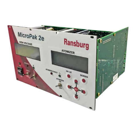
Located on the front panel of the Channel Module are
several status indicator lights (LEDs). These are:
1. CPU - Is ON when the microprocessor is
operating normally.
2. ACTIVE - Is ON when communication is taking
place to the Interface Module.
3. FAULT - Is ON when there is a problem with
the module.
Interface Module
The Interface Module performs the following:
• Stores system conguration and data tables.
• Acts as an interpreter for communication with an external
Host computer, PLC and/or the local Operator Interface.
Communicates through a high speed Ransburg CAN
Bus data link to each Channel Module.
• Responsible for system specic inputs and supplying the
necessary system specic outputs for control and status.
Located on the front panel of the Interface Module are
several status indicator lights (LEDs). These are:
1. CPU - Is ON when the microprocessor is
operating normally.
2. ACTIVE - Is ON when RIO communication is
taking place to an Allen-Bradley PLC.
3. FAULT - Is ON when there is a problem with
the module.
Local Operator Interface
Supplied as part of the DynaFlow Stand-Alone Control
Cabinet, Model# 77376 and A12233.
• Permits total control of the system.
• Displays system conguration and data to the operator.
• Computes and displays text and graphic diagnostic
information.
• Organizes, formats, and reports all data and
conguration tables.
The DynaFlow uid ow control system achieves real-time
closed loop control through the use of CHANNELs and
GUNs. A CHANNEL consists of an electrical-to-pneumatic
(E/P) transducer, material regulator and uid ow meter
combination through which a single material is controlled.
A GUN represents a single applicator through which one or
more materials are delivered. One or more CHANNELs are
congured for each GUN. Two-component delivery systems
(referred to as 2K systems) have two CHANNELs assigned
to a single GUN. The materials are statically mixed before
being delivered to the GUN.
Each CHANNEL operates independently of, and
simultaneously with all the other CHANNELs. This lets the
DynaFlow controller provide accurate dynamic regulation
for each CHANNEL, regard-less of minor system wear or
changes in system variables. With a single-component
coating material, the DynaFlow controller detects changes
from the programmed ow rate and adjusts the output
to correct it. With two-component coatings (where both
the resin and catalyst are regulated and monitored), the
DynaFlow controller detects any change in the total ow
and makes the required adjustments to maintain the
programmed ow and ratio. This holds the ow rates of the
coating components constant. Deviations from the desired
mix ratio are also immediately corrected using this same
closed loop process.
A detailed guide on PID control is supplied in this manual to
assist you should you want to adjust the control parameters.
There are many additional features included in the DynaFlow
Fluid Flow Control which reect on the many years of
experience accumulated by Ransburg.
The control rack and OPERATOR INTERFACE panels are
consistent with and easily integrated with other Ransburg
control products into larger custom system control panels.
This optimizes costs, space and functionality for control of
multiple applicator spray stations. Spray stations may also
incorporate rotary atomizer speed control, shaping air, high
voltage power supplies and more.
The standard stand-alone control cabinet includes control of
up to 8 CHANNELs. It incorporates an integrated 15” color
LCD touch screen, PC based display/interface sub-panel.
Return To Contents
LN-9400-00-R11 (08/2018) 10 / 96 www.carlisleft.com
INTRODUCTION


