CARLO GAVAZZI DWB02 User manual

Specifications are subject to change without notice (16.10.08) 1
Monitoring Relays
3-Phase Active power
Types DWB02, PWB02
•TRMS active power relays for three phase
balanced applications
•Measuring if active power is within set limits
•Measuring voltage on own power supply
•Measuring ranges: 5A, 10A, MI current transformers
•Power ON delay 1 to 30 s knob selectable
•Separately adjustable upper/lower level on relative
scale
•Programmable latching or inhibit at set level
•Automatic and manual start and stop of the system
•Output: 8 A SPDT relay N.D. or N.E. selectable
•For mounting on DIN-rail in accordance with DIN/EN
50 022 (DWB02) or plug-in module (PWB02)
•45 mm Euronorm housing (DWB02) or 36 mm plug-in
module (PWB02)
•LED indication for relay, alarm and power supply ON
Product Description
DWB02 and PWB02 are
precise TRMS active power
monitoring relays for 3-
phase balanced systems.
They can be used for moni-
toring the actual load of
asynchronous motors and
other symmetrical loads, as
well as the power consump-
tion by of system.
Start/stop input allows to
use a manual switch to start
and stop the system, with-
out the need of an auxiliary
device.
The advantage of using the
latch function is that the
alarm status can be kept
even after the end of the
alarm condition. Inhibit func-
tion can be used to avoid
relay operation when not
desired (maintenance, tran-
sitions).
The LED's indicate the state
of the alarmand the output
relay.
Input Specifications
Input
Voltage (Own power supply):
3-phase DWB02: L1, L2, L3
PWB02: 5, 6, 7
M23: 208 to 240 VAC ± 15%
DWB02CM48: 380 to 480 VAC ± 15%
PWB02CM48: 380 to 415 VAC ±15%
DWB02CM69: 600 to 690 VAC ± 15%
1- phase DWB02CM23: L1, L2
PWB02CM23: 5, 6
208 to 240 VAC ± 15%
Current: DWB02: 5A, 10A: I1, I2
MI...:U1, U2
PWB02: 5A, 10A: 11, 10
MI...: 9, 8
Measuring ranges Upper level Lower level
Active power 10 to 110 % 10 to 110 %
AACrms Max. curr.
(30s)
Direct input: 0.5 to 5A 30A
1 to 10A 50A
Standard CT (examples)
TADK2 50 A/5 A 5 to 50 A 60 A
CTD1 150 A/5 A 15 to 150 A 180 A
CTD4 400 A/5 A 40 to 400 A 480 A
TAD12 1000 A/5 A 100 to 1000 A 1200 A
TACO200 6000 A/5 A 600 to 6000 A 7200 A
MI CT ranges
MI 100 10 to 100 A 250 AAC
MI 500 50 to 500 A 750 AAC
Note:
The input voltage cannot
raise over 300 VAC with
respect to ground (PWB02
only)
Contact input
DWB02 Terminals Z1, U2
PWB02 Terminals 2, 9
Disabled > 10 kΩ
Enabled <500 Ω
Pulse width > 500 ms
Hysteresis ~2% of set value - fixed
DWB02 PWB02
Ordering key
Housing
Function
Type
Item number
Output
Power Supply
Range
DWB 02 C M48 10A
Type Selection
Mounting Output Supply: Supply: Supply: Supply:
208 to 240 VAC 380 to 415 VAC 380 to 480 VAC 600 to 690 VAC
DIN-rail SPDT DWB 02 C M23 10A DWB 02 C M48 10A DWB02 C M69 10A
Plug-in SPDT PWB 02 C M23 10A PWB 02 C M48 10A

2Specifications are subject to change without notice (16.10.08)
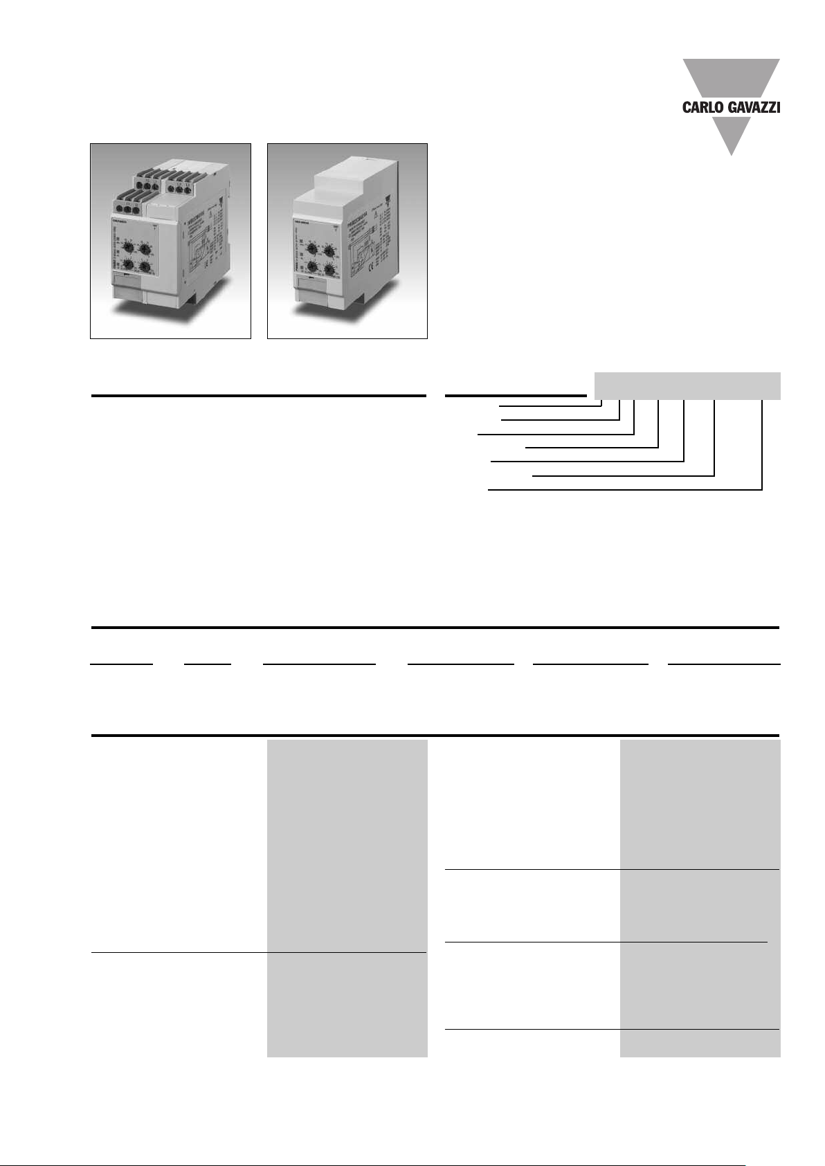
DWB02, PWB02
Supply Specifications
General Specifications
Power supply Overvoltage cat. III
Rated operational voltage (IEC 60664, IEC 60038)
Through terminals:
DWB02: L1, L2, L3
PWB02: 5, 6, 7
M23 177 to 276 VAC 45 to 65 Hz
DWB02CM48 323 to 552 VAC 45 to 65 Hz
PWB02CM48 323 to 477 VAC 45 to 65 Hz
DWB02CM69 510 to 793 VAC 45 to 65 Hz
Dielectric voltage supply to output 4kV
Rated operational power
M23 9 VA@230 V,50 Hz
M48 13 VA @ 400 V, 50 Hz
M69 21 VA @ 600 V, 50 Hz
Supplied by L1 and L2
Power ON delay 1to 30 s ± 0.5 s
Reaction time (input signal variation from
-20% to +20% or from
+20% to -20% of set value)
Alarm ON delay < 250 ms
Alarm OFF delay < 250 ms
Accuracy (15 min warm-up time)
Temperature drift ± 1000 ppm/°C
Delay ON alarm ± 10% on set value ± 50 ms
Repeatability ± 0.5% on full-scale
Indication for
Power supply ON LED, green
Alarm ON LED, red (flashing 2 Hz
during delay time)
Output relay ON LED, yellow
Environment
Degree of protection IP 20
Pollution degree 3 (DWB02), 2 (PWB02)
Operating temperature
@Max. voltage, 50 Hz -20 to +60°C, R.H. < 95%
@Max. voltage, 60 Hz -20 to +50°C, R.H. < 95%
Storage temperature -30 to +80°C, R.H. < 95%
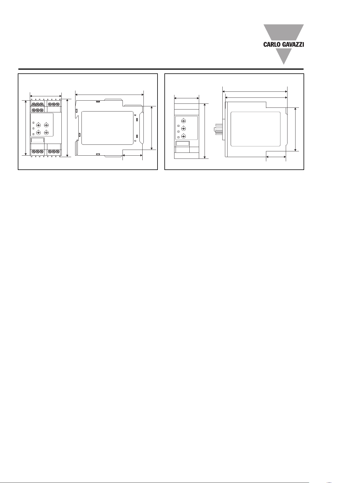
Housing
Dimensions DWB02 45 x 80 x 99.5 mm
PWB02 36 x 80 x 94 mm
Weight Approx. 250 g
Screw terminals
Tightening torque Max. 0.5 Nm
acc. to IEC 60947
Approvals UL, CSA
CE-Marking Yes
EMC Electromagnetic Compatibility
Immunity According to EN 61000-6-2
Emission According to EN 61000-6-3
Mode of Operation
DWB02 and PWB02 mea-
surethe active power of a 3-
phase balanced system. The
relay has an adjustable pow-
er ON delay in order to avoid
undesired overload detec-
tion during motor start.
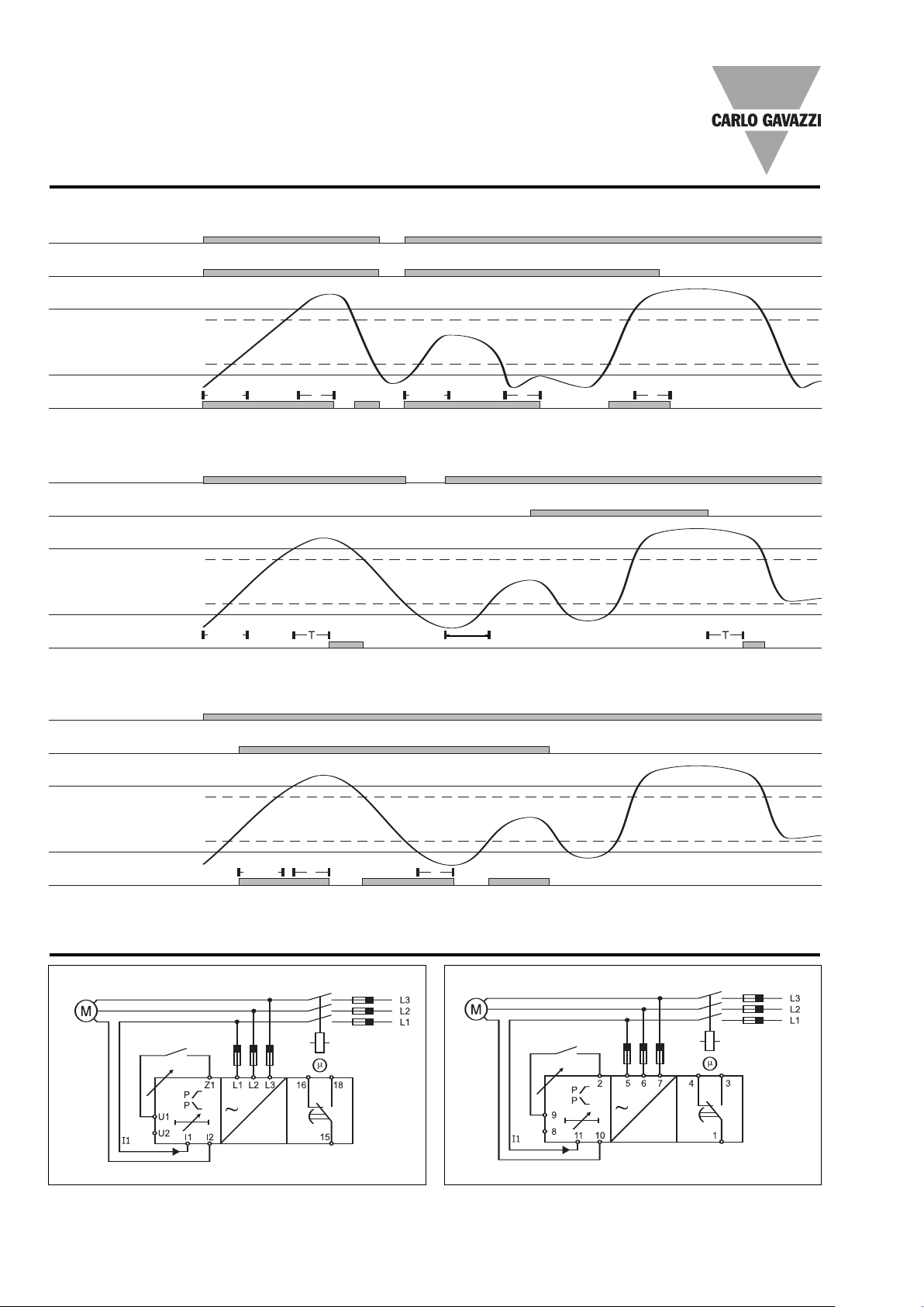
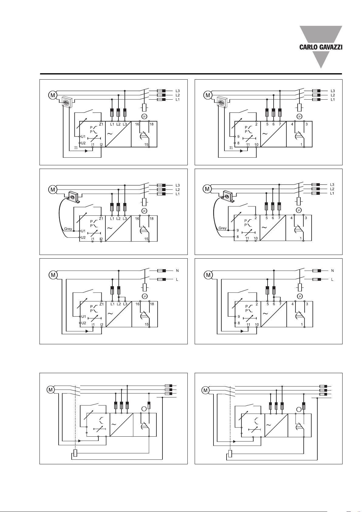
Example 1
Latching mode, relay NE
In this application DWB02 or
PWB02 is connected to an
external current metering
transformer,type MI..., (con-
nected between U1 & U2) as
well as to a 3-phase asyn-
chronous motor. The relay is
energized as soon as the
power supply is applied.
After the power ON delay,
the unit starts to measure
power. If it is within the set-
points, the relay is ener-
gized, and the yellow LED is
ON. As soon as the power
drops below the lower set-
point or raises above the
upper setpoint the output
relay releases after the set
time has expired. To restart
the measurement, connect
Z1 and U1 (2 and 9) or inter-
rupt the power supply for at
least 1 s.
Example 2
Non-latching mode, relay
NE.
DWB02 and PWB02 react
as described in the previous
example 1 except that the
relay reactivates automati-
cally as soon as active pow-
er is back within the two
setpoints again. When the
measured power rises
above the adjusted upper
level, the red LED starts
flashing, and the output
relay releases after the set
time period. When the mea-
sured power drops below
the adjusted lower level, the
red LED starts flashing, and
the output relay releases
after the set time period.
Example 3:
DWB02CM2310A and
PWB02CM2310A can be
used for monitoring the
power of a 1-Phase load
with 208 to 240 V AC mains
voltage. In this case the
power supply has to be con-
nected between L1, L2 (or 5,
6); L2 and L3 (or 6 and 7)
have to be interconnected.
Example 4
Start/stop mode, relay NE.
In this application DWB02 or
PWB02 are directly connect-
ed to a 3-phase asyn-
chronous motor.The relay is
energized as soon as the
power supply is applied and
the start/stop contact is
closed. After the power ON
delay,the unit starts to mea-
sure the active power. If it is
within the setpoints the relay
is energized. As soon as the
power drops below the low-
er setpoint or raises above
the upper setpoint the out-
put relay releases and the
red LED turns on after the
set time has expired. When
the start/stop contact is
opened the relay is immedi-
ately de-energized. To
Output Specifications
Output SPDT relay
Rated insulation voltage 250 VAC
Contact ratings (AgSnO2)µ
Resistive loads AC 1 8 A @ 250 VAC
DC 12 5 A @ 24 VDC
Small inductive loads AC 15 2.5 A @ 250 VAC
DC 13 2.5 A @ 24 VDC
Mechanical life ≥30 x 106operations
Electrical life ≥105operations
(at 8 A, 250 V, cos ϕ=1)
Operating frequency ≤7200 operations/h
Dielectric strength
Dielectric voltage ≥2kVAC (rms)
Rated impulse withstand volt. 4 kV (1.2/50 µs)

Specifications are subject to change without notice (16.10.08) 3
DWB02, PWB02
Function/Range/Level/Time Setting
Select the desired function
setting the DIP-switches 1
to 4 as shown on the right.
Adjust the input range set-
ting the DIP-switches 5 and
6. To access the DIP-
switches open the plastic
cover using a screwdriver as
shown below.
If DIP switch 3 is set to ON
(start/stop) the position of
DIP switch 4 does not affect
the products’ working
mode.
Center knobs:
Setting of upper and lower-
level from 10 to 110% of
nominal power.
Lower left knob:
Setting of delay on absolute
scale: 0.1 to 30 s.
Lower right knob:
Setting of power ON delay
on absolute scale: 1 to 30 s.
Measuring range
SW5 ON ON OFF OFF
SW6 ON OFF ON OFF
M23 208 VAC 220 VAC 230 VAC 240 VAC
M48 380 VAC 400 VAC 415 VAC 480 VAC
DWB02 only
M69 600 VAC 690 VAC 600 VAC 690 VAC
Contact input (SW3 OFF)
ON: Latch function enable
OFF: Inhibit function enable
Working mode
ON: Contact input for start/stop functions
OFF: Contact input for latch/inhibit functions
Input current range (terminals I1, I2 or 10, 11)
ON: 10A
OFF: 5A/MI
Relay status
ON: Relay de-energized in normal condition
OFF: Relay energized in normal condition
Contact input working mode
CLOSED OPEN
LATCH NOT ACTIVE ACTIVE
INHIBIT ACTIVE NOT ACTIVE
START/STOP START STOP
Mode of Operation (cont)
restart the system just con-
nect the start/stop contact.
Note 1: to use the start/stop
function the output relay has
to command a contactor in
series to the load (see last
two wiring diagrams).
Note 2 (3-phase voltage):
connect the 3-phase power
supply to the terminals L1,
L2 and L3 (DWB02) - 5, 6
and 7 (PWB02) taking care
of the sequence.
Contact input
DWB02
Contact input
PWB02
Notes
1.DIP-switch 3 set ON enables the start/stop function
that is managed by the closing-opening of the
contact input.
2.DIP-switch 3 set OFF enables the input contact
for the latch/inhibit functions: the selection between
these is allows by the DIP switch 4.
The following table shown as the input contact man-
ages the mode of operation:

4Specifications are subject to change without notice (16.10.08)
DWB02, PWB02
Operation Diagrams
T T T
Latch function - NE relay
Inhibit function - ND relay
Power supply
Latch contact
(Closed = latch not active)
Upper level
Hysteresis
Hysteresis
Active power Power
ON
Power
ON
Power
ON
Lower level
Relay ON
Power supply
Inhibit contact
(Closed = inhibit active)
Upper level
Hysteresis
Hysteresis
Active power
Lower level
Relay ON
Wiring Diagrams
DWB02 - Direct connection PWB02 - Direct connection
Latch/Inhibit
Contact
Latch/Inhibit
Contact
T T
Start and stop function - NE relay
Power
ON
Power supply
Start/Stop contact
(Closed = Start; Open = Stop)
Upper level
Hysteresis
Hysteresis
Active power
Lower level
Relay ON
Power ON

Specifications are subject to change without notice (16.10.08) 5
PWB02CM2310A - Direct connection - 1-Phase LoadDWB02CM2310A - Direct connection - 1-Phase Load
DWB02 - MICT PWB02 - MICT
DWB02, PWB02
Latch/Inhibit
Contact
Latch/Inhibit
Contact
Latch/Inhibit
Contact Latch/Inhibit
Contact
DWB02 - Standard CT PWB02 - Standard CT
Latch/Inhibit
Contact
Latch/Inhibit
Contact
L2 L3L1
m
15
16 18
L1
L2
L3
U1
U2
Z1
I2I1
I1
N
P
P
675
m
1
43
L1
L2
L3
9
8
2
1011
I1
N
P
P
PWB02 - Direct connection - Manual start and stop (NE relay)DWB02 - Direct connection - Manual start and stop (NE relay)
Start/stop
Contact Start/stop
Contact
Wiring Diagrams (cont.)
With the start/stop function enabled, it’snecessaryto use the following wiring diagrams (which aretwo examples among
many others). It is possible for both 3-phases loads and of 1-phase loads, either through direct connection or external cur-
rent metering transformer.

6Specifications are subject to change without notice (16.10.08)
DWB02, PWB02
45
80
83.5
99.5
63
28.5
36
80
94
28.5
63
90
Dimensions
DIN-rail Plug-in
This manual suits for next models
1
Table of contents
Other CARLO GAVAZZI Relay manuals

CARLO GAVAZZI
CARLO GAVAZZI DIB01CB23 User manual

CARLO GAVAZZI
CARLO GAVAZZI DPD02DM44B User manual

CARLO GAVAZZI
CARLO GAVAZZI RF1 Series User manual

CARLO GAVAZZI
CARLO GAVAZZI RSGT User manual

CARLO GAVAZZI
CARLO GAVAZZI DPB01 User manual

CARLO GAVAZZI
CARLO GAVAZZI D/P PB01CM23/N User manual

CARLO GAVAZZI
CARLO GAVAZZI RHS00 Assembly instructions

CARLO GAVAZZI
CARLO GAVAZZI RGC1A User manual

CARLO GAVAZZI
CARLO GAVAZZI DWB03 User manual

CARLO GAVAZZI
CARLO GAVAZZI DPB01 User manual