CARLO GAVAZZI RGC1A User manual

Solid State Relay
Number of poles
Switching Mode
Rated perational Voltage
Control voltage
Rated perational current
Connection type for control
Connection type for power
Connection configuration
ption
Specifications are subject to change without notice (14.04.2010) 1
•Zero Crossing or Instant- n (Random) Switching
•Product Width 17.5mm, 22.5mm
•Rated perational voltage: Up to 600Vrms
•Rated perational Current: Up to 30Arms
•Up to 1800A²s for I²t and 1200Vp for blocking voltage
•Control voltages: 3-32 VDC, 20-275 VAC (24-190 VDC)
•IP20 protection
•Design according to IEC60947-4-2, IEC60947-4-3,
IEC62314, UL508, CSA 22-2 No. 14-05
•Integrated voltage transient protection with varistor
•RoHS compliant
Product Description Ordering Key
This new range of solid state
contactors presents a unique
opportunity to maximize effi-
ciency in panel space and is an
evolution of solid state switch-
es for which Carlo Gavazzi is
very well known.
The latest technologies in elec-
tronic and power semicondcu-
tor design allows a slim design
incorporating product ratings
at a surrounding temperature
of 40°C. The smallest width is
17.5mm and is rated at
20 AAC. Power and control
teminals allow for safe looping
of cables. Voltage transient
protection is standard across
the output with a varistor.
Specifications are stated at
25°C unless otherwise noted.
Solid State Relays
Zero Switching
Types RGC Solid State Contactor 'E' (Contactor) Connection
Rated utput Blocking Connection Control Voltage Rated perational Current
Voltage Voltage Control/ Power 20 AAC 30 AAC
230 VAC, ZC 800Vp Screw/Screw 3 - 32 VDC RGC1A23D20 E RGC1A23D30 E
20 - 275 VAC, 24-190 VDC RGC1A23A20 E RGC1A23A30 E
600 VAC, ZC 1200Vp Screw/Screw 4 - 32 VDC RGC1A60D20 E RGC1A60D30 E
20 - 275VAC, 24-190 VDC RGC1A60A20 E RGC1A60A30 E
600 VAC, IO 1200Vp Screw/Screw 4 - 32 VDC RGC1B60D20 E RGC1B60D30 E
Selection Guide (ZC: Zero Cross Switching, IO = Instant-On Switching)
RGC 1 A 60 A 30 K K E _
Ordering Key
1Phase SSR Rated Voltage Control Voltage Rated Connection Connection Connection
with heatsink Current Control utput configuration
RGC1A: ZC 23: 230V +10% - 15%, 800Vp D: 3 or 4-32VDC 20: 20AAC : Screw : Screw E: Contactor
RGC1B: IO 60: 600V +10% -15%, 1200Vp A: 20 - 275VAC, 24-190 VDC 30: 30AAC

2Specifications are subject to change without notice (14.04.2010)
RGC
Output Voltage Specifications
RGC..23.. RGC..60..
Operational Voltage Range 24-240 VAC, 42-600 VAC,
+10%, -15% on max +10% -15% on max
Blocking Voltage 800Vp 1200 Vp
Internal Varistor 275V 680V
Input specifications
Latching voltage
(across L1-T1) ≤20V
Operational frequency
range 45 to 65Hz
Power factor > 0.5 @ Vrated
Finger Protection IP20
Control input status continuously ON Green LED,
when control input is applied
Pollution degree 2
(non-conductive pollution with
possibilities of condensation)
Over-voltage category III
(fixed installations)
General Specifications Isolation
Input to Output 4000Vrms
Input & Output to Case 4000Vrms
AC input current Vs Input Voltage
DC input current Vs Input Voltage
RGS..D..1RGS..A..
Control voltage range RGC..23.. 3 - 32 VDC 20 - 275 VAC,
24 (-10%) - 190 VDC
RGC..60.. 4 - 32 VDC 20-280 VAC,
24 (-10%) - 190 VDC
Pick-up voltage RGC..23.. 3.0 VDC 20 VAC/DC
RGC..60.. 3.8 VDC
Drop-out voltage RGC..23.. 1.2 VDC 5 VAC/DC
RGC..60.. 1.2 VDC
Maximum Reverse voltage 32 VDC -
Response time pick-up ZC (RGS1A..) 0.5 cycle + 500µs @ 24VDC 0.5 cycle + 40µs
@ 230VAC/110VDC
Response time pick-up IO (RGS1B..) 350µs @ 24 VDC N/A
Response time drop-out 0.5 cycle + 500µs @ 24VDC 2 cycles
Input current @ 40°C See diagrams below See diagrams below
1: DC control to be supplied by a Class 2 power source
RG..D.. RG..A..

Specifications are subject to change without notice (14.04.2010) 3
2 x: multiple of AC53a rating, Tx: duration of current surge, F: duty cycle.
RGC
Motor Ratings: HP (UL50 ) / kW (IEC60947-4-2) @ 40°C
115 VAC 230 VAC 400 VAC 480 VAC 600 VAC
RGC..20 ½HP / 0.18kW 1-½HP / 0.37kW 2HP / 0.75kW 3HP / 1.1kW 3HP / 1.5kW
RGC..30 3/4HP / 0.37kW 2HP / 1.1kW 3HP / 1.5kW 5HP / 2.2kW 5HP / 3.7kW
Output specifications
RGC..20.. RGC..30..
Rated operational current
AC-51 rating @ Ta=40°C 20 AAC 30 AAC
AC-53a rating @ Ta=40°C 5 AAC 10 AAC
Number of starts (x:6, Tx:6s, F:50%) at 40˚C 230 30
Min. operational current 150 mAAC 250 mAAC
Rep. overload current -
UL508: TAMB=40°C, tON=1s, tOFF=9s, 50cycles 60 AAC 84 AAC
Maximum transient surge current (ITSM) 325 Ap 600 Ap
Maximum off-state leakage current 3 mA 3 mA
I²t (10ms) Typical 525 A²s 1800 A²s
Crititcal dv/dt (@ Tj = 40°C) 1000 V/us 1000 V/us
Output Power Dissipation Current Derating
0W
3W
6W
9W
12W
15W
18W
21W
24W
27W
30W
33W
RGC1..20
Load Current (AAC)
Power Dissipation (W)
RGC1..30

4Specifications are subject to change without notice (14.04.2010)
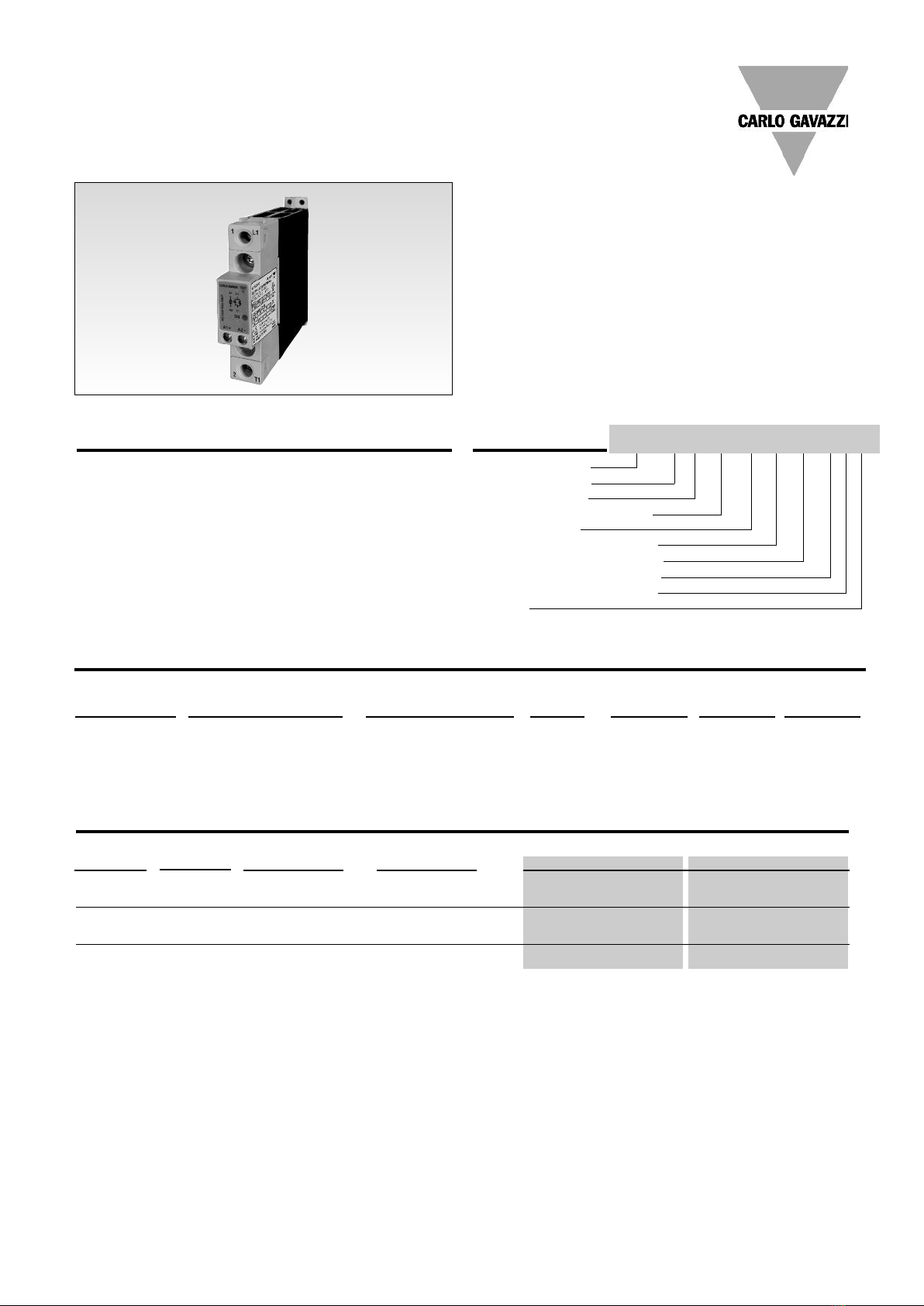
RGC
Note:
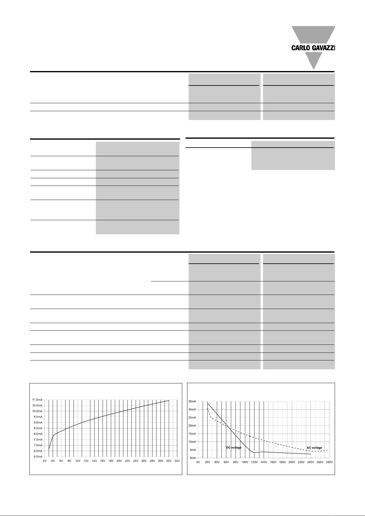
• Control input lines must be installed together to maintain products' susceptability to Radio Frequency interference.Use of AC solid state relays may,
according to the application and the load current, cause conducted radio interferences. Use of mains filters may be necessary for cases where the user must
meet E.M.C requirements. The capacitor values given inside the filtering specification tables should be taken only as indications, the filter attenuation will
depend on the final application. DC input type require surge suppression for full compliance to EN55011.
• Performance Criteria 1: No degradation of performance or loss of function is allowed when the product is operated as intended.
• Performance Criteria 2: During the test, degradation of performance or partial loss of function is allowed. owever when the test is complete the
product should return operating as intended by itself.
• Performance Criteria 3: Temporary loss of function is allowed, provided the function can be restored by manual operation of the controls.
Conformance IEC/EN 62314
IEC/EN 60947-4-2
IEC/EN 60947-4-3
EMC Immunity IEC/EN 61000-6-4
EMC Emission IEC/EN 61000-6-2
Electrostatic Discharge (ESD)
Immunity IEC/EN 61000-4-2
Air discharge 8kV, Performance Criteria 2
Contact 4kV, Performance Criteria 2
Electrical Fast Transient
Burst Immunity IEC/EN 61000-4-4
Output 2kV, Performance Criteria 1
Input 1kV, Performance Criteria 1
Electrical Surge Immunity IEC/EN 61000-4-5
Output, line to line 1kV, Performance Criteria 1
Output, line to earth 2kV, Performance Criteria 1
Input, line to line 1kV, Performance Criteria 2
Input, line to earth 2kV, Performance Criteria 2
Radio Interference
voltage emission (conducted) IEC/EN 55011
0.15 - 30MHz Class A (industrial)
- see filter information
IEC/EN 60747-4-X
Class A (no filtering needed)
Agency Approvals UL508 LIS ED (E172877),
VDE (pending), CUL
Radiated Radio Frequency
Immunity IEC/EN 61000-4-3
10V/m, 80 - 1000 Mhz Performance Criteria 1
10V/m, 1.4 - 2.0GHz Performance Criteria 1
1V/m, 2.0 - 2.7GHz Performance Criteria 1
Conducted Radio Frequency
Immunity IEC/EN 61000-4-6
10V/m, 0.15 - 80 MHz Performance criteria 1
Voltage Dips Immunity IEC/EN 61000-4-11
0% for 10ms/20ms,
70% for 500ms Performance Criteria 2
40% for 200ms Performance Criteria 2
Voltage Interruptions Immunity IEC/EN 61000-4-11
0% for 5000ms Performance Criteria 2
Radio Interference
voltage emission (conducted) IEC/EN 55011
0.15 - 30MHz Class A (industrial)
- see filter information
Agency Approvals and Electromagnetic Compatibility
Filtering - EN / IEC 55011 Class A compliance (for class B compliance contact us)
Part Number Suggested filter for compliance Maximum Heater current
RGC1A23D20KKE 68 nF / 275 V / X1 20A
RGC1A23A20KKE 220 nF / 275 V / X1 30A
RGC1A60D20KKE 100 nF / 1000 V / X1 20A
RGC1A60A20KKE 330 nF / 1000 V / X1 30A

Specifications are subject to change without notice (14.04.2010) 5
RGC
Operating Temperature -40°C to 80°C (-40˚F to +176˚F)
Storage Temperature -40°C to 100°C (-40˚F to +212˚F)
Ro S (2002/95/EC) Compliant
Impact resistance
(IEC60068-2-27) 15/11 g/ms
Vibration resistance
(2-100 z, IEC60068-2-26) 5g
Relative humidity 95% non-condensing @ 40˚C
UL flammability rating
(housing) UL 94 V0
1/L1: Supply connection
2/T1: Load connection
A1(+): positive control signal
A2(-): control ground
Environmental Specifications
Dimensions
Terminal Layout
* ousing width tolerance +0.5mm, -0mm…as per DIN43880
All dimensions in mm
5
3.2
17.8
19.5
106
98
90
135.6
35.4
50.6
Connection Diagram
Filter Connection diagram
In AC controlled types only (RG..A..) a
varistor is placed across A1/A2 terminals.
In DC controlled types only (RG..D..) a diode is placed in series
with the control circuit for protection against reverse biased
connection.
A1 ~ 1 L1
A2 -2T1

6Specifications are subject to change without notice (14.04.2010)
RGC
Installation Instructions
X =
product
width
Y2 =
100mm
Y1 = 5mm
Connection Specifications
PWER C NNECTI NS: 1/L1, 2 /T2
Tor ue specifications
2Nm (17.7 in-lb)
M4, Pozidriv 2
Use 75°C copper (Cu)
conductors
Stripping Length (X) = 11mm
Rigid (Solid & Stranded)
UL/ CSA rated data
2 x 2.5..6 mm22 x 2.5..6 mm2
2x 14..10 AWG 1 x 14..10 AWG
Flexible with end sleeve
2x 2.5..4mm22x 2.5..4mm2
2x 14..12AWG 1 x 14..12AWG
Flexible without end sleeve
2 x 2.5..6 mm21 x 2.5..6 mm2
2x 14..10 AWG 1 x 14..10 AWG
Aperture for termination lug 12.3mm
C NTR L C NNECTI NS: A1(+), A2(-)
Tor ue specifications
0.5 Nm (4.4 in-lb)
M3, Pozidriv 1
Use 60/75°C copper (Cu)
conductors
Stripping Length (X) = 6mm
Rigid (Solid & Stranded)
2x 0.5..2.5mm21x 0.5..2.5mm2
2x 18..12 AWG 1 x 18..12 AWG
Flexible with end sleeve
2x 0.5..2.5mm21x 0.5..2.5mm2
2 x 18..12AWG 1 x 18..12AWG
Protective Earth Connection
RGC..20: M4; RGC..30: M5
1.5Nm (13.3 in-lb)
Note: Protective Earth connection must be connected whenever the product
is intended to be used in Class 1 applications according to EN/IEC 61140.
X
X

Specifications are subject to change without notice (14.04.2010) 7
RGC
Co-ordination type 1 (UL50 )
Part No. Max. si e [A] Class Current [kA] Voltage [VAC]
RGC..20 30 RK5 5 Max. 600
RGC..30 30 RK5 5 Max. 600
Short Circuit Protection
Protection Co-ordination, Type 1 vs Type 2:
Type 1 protection implies that after a short circuit, the device under test will no longer be in a functioning state. In type 2 co-ordination the device under test
will still be functional after the short circuit. In both cases, however the short circuit has to be interrupted. The fuse between enclosure and supply shall not
open. The door or cover of the enclosure shall not be blown open. There shall be no damage to conductors or terminals and the condcutors shall not sepa-
rate from terminals. There shall be no breakage or cracking of insulating bases to the extent that the integrity of the mounting of live parts is impaired.
Discharge of parts or any risk of fire shall not occur.
The product variants listed in the table hereunder are suitable for use on a circuit capable of delivering not more than 5,000 A rms Symmetrical Amperes, 600
Volts maximum when protected by fuses. Tests at 5,000 A were performed with RK5 fuses, time delay; please refer to the table below for maximum allowed
ampere rating of the fuse. Use fuses only.
This manual suits for next models
11
Table of contents
Other CARLO GAVAZZI Relay manuals

CARLO GAVAZZI
CARLO GAVAZZI RHS00 Assembly instructions

CARLO GAVAZZI
CARLO GAVAZZI RSGT User manual

CARLO GAVAZZI
CARLO GAVAZZI DPB01 User manual

CARLO GAVAZZI
CARLO GAVAZZI DPB01 User manual

CARLO GAVAZZI
CARLO GAVAZZI DPD02DM44B User manual

CARLO GAVAZZI
CARLO GAVAZZI DPC01 User manual

CARLO GAVAZZI
CARLO GAVAZZI BTM-T15-PLUS User manual

CARLO GAVAZZI
CARLO GAVAZZI RG Series User manual

CARLO GAVAZZI
CARLO GAVAZZI DWB02 User manual

CARLO GAVAZZI
CARLO GAVAZZI DWB03 User manual