Carlos mendoza Blanco User manual

PART 4 USING A DMX512 CONTROLLER....................................10.
4.1--BASIC ADDRESSING.................................................................10.
4.2--CHANNELASSIGNMENT............................................................10.
4.3--BASIC INSTRUCTIONS FORDMX512 OPERATION......................12.
PART 3 DISPLAY PANEL OPERATION.........................................7.
3.1--BASIC..........................................................................................7.
3.2--MENU..........................................................................................7.
3.4--DMX512 SETTINGS......................................................................8.
3.5--RUN MODE..................................................................................8.
3.6--PERSONALITY............................................................................8.
3.7--ID ADDRESS...............................................................................9.
3.8--SPECIAL SETTINGS.................................................................... 9.
3.9--A CTIVATETHE PASSWORD ....................................................... 9.
3.10--WHITES SETTING ..................................................................... 9.
PART 1 PRODUCT (GENERAL)....................................................1.
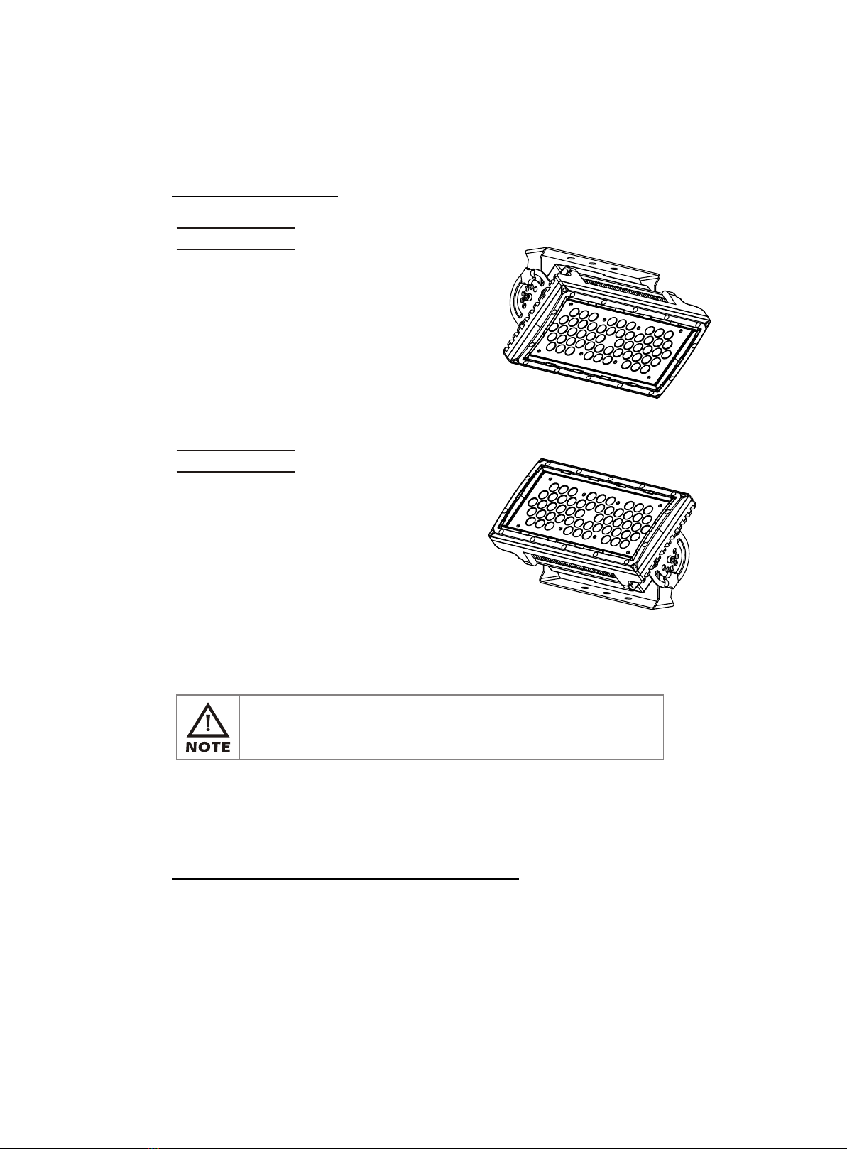
1.1--PRODUCT INTRODUCTION.........................................................1.
1.2--PRODUCT FEATURES.................................................................1.
1.3--TECHNICAL SPECIFICATIONS.....................................................2.
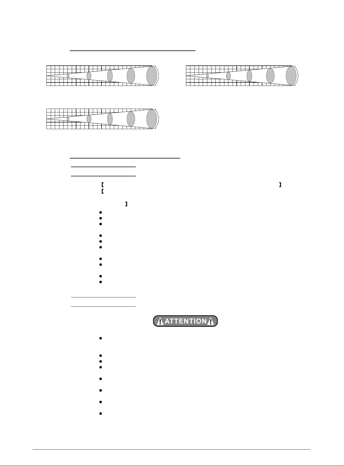
1.4--PHOTOMETRIC DATA..................................................................3.
1.5--SAFETY WARNING......................................................................3.
PART 2 INSTALLATION...............................................................4.
2.1--MOUNTING...................................................................................4.
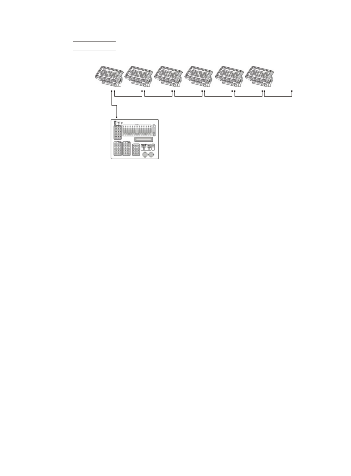
2.3--SETTING UPWITHA DMX512 CONTROLLER.................................5.
2.3-1--DMX512ADDRESSING WITHOUTID ADDRESSING......................................5.
2.3-2--DMX512 ADDRESSING WITHID ADDRESS..................................................5.
2.2--POWER CONNECTION................................................................. 4.
3.3--EDIT STATICCOLOUR.................................................................8.
PART 5 APPENDIX......................................................................13.
5.1--TROUBLE SHOOTING...............................................................13.
5.2--MAINTENANCE........................................................................ 14.
ABLE OF CONTENTS
T
www.carlosmendoza.com.mx - (55) 56 72 85 69 - 72*15*18765

1.1 PRODUCT INTRODUCTION
This product is designed for indoor or outdoor use. Suitable applications include wash or
effect lighting for architectural, stage or nightclub applications. This product can also be
installed for use in signage and advertising using the dynamic functions available with
DMX512 control. Direct input of DMX512 signal allows the units to be controlled from any
DMX512 controller. This product can be operated as a single unit or in multiple units for
large applications.
1.2 PRODUCT FEATURES
LED FIXTURE
1 PRODUCT(GENERAL) 1
* RGBDimmer 0-100%
* Strobe
* IP65protection rating
* LCD display
* Display control'lock-out'
* DirectDMX512 input
* Independent IDaddress
* Lightweightaluminium casing
* Differentwhite colors setting
2008.9.19
1 PRODUCT (GENERAL)
www.carlosmendoza.com.mx - (55) 56 72 85 69 - 72*15*18765

1.3 TECHNICAL SPECIFICATIONS
LED MODULE
Dimensions
LED MODULE:
Voltage
Rated Power
IP65 protection rating
54pcs (42 xWhite / 12x Amber)
Weight
LED/Unit
Output/LED
Cooling
IP
1W
Direct air convection
380 x 200x 190mm
8Kg
100~240V...50/60Hz
80W
1 PRODUCT(GENERAL) 2
Environment Temperature -20 ~40
2008.9.19
380mm
190mm
200mm
www.carlosmendoza.com.mx - (55) 56 72 85 69 - 72*15*18765

1.4 PHOTOMETRIC DATA
1 PRODUCT(GENERAL) 32008.9.19
1.5 SAFETY WARNING
IMPORTANT
ALWAYS READ THE USER MANUAL BEFORE OPERATION.
PLEASE CONFIRM THAT THE POWER SUPPLY STATED ON THE
PRODUCT IS THE SAME AS THE MAINS POWER SUPPLY IN YOUR
AREA.
This product must be installed by a qualified professional.
Always operate the equipment as described in the user manual.
A minimum distance of 0.5m must be maintained between the equipment and
combustible surface.
The product must always be placed in a well ventilated area.
Always makesure that the equipment is installed securely.
DO NOT stand close to the equipment and stare directly into the LED light
source.
Always disconnectthe power supply before attempting and maintenance.
Always make sure that the supporting structure is solid and can support the
combined weight ofthe products.
The earth wire must always be connected to the ground.
Do not touchthe power cablesif your handsare wet.
ATTENTION
This product leftthe place ofmanufacture in perfectcondition. In orderto
maintain this condition and for safe operation, the user must always follow the
instructions and safety warnings described in this user manual.
Avoid shaking or strong impactsto any partof the equipment.
Make sure thatall parts ofthe equipment arekept clean andfree of dust.
Always make sure that the power connections are connected correct and
secure.
If there is any malfunction of the equipment, contact your distributor
immediately.
When transferring the product, it is advisable to use the original packaging in
which the productleft the factory.
Shields, lenses orultraviolet screens shallbe changed ifthey have become
damaged to such an extent that their effectivenessis impaired.
The lamp (LED) shall be changed if it has become damaged or thermally
deformed.
WHITE
1
2
3
0
1
2
3
246810Distance(m)
3338 900 410 247 166 LUX
15
AMBER
WHITE+AMBER
1
2
3
0
1
2
3
246810Distance(m)
1261 361 155 90 62 LUX
15
1
2
3
0
1
2
3
246810Distance(m)
4795 1270 567 331 226 LUX
15
www.carlosmendoza.com.mx - (55) 56 72 85 69 - 72*15*18765

2.1 MOUNTING
HANGING
UPRIGHT
The LEDbloc can be mounted in an upright or
sitting position usingthe supporting brackets.
The LEDbloc can be mounted in a hanging
position using the supporting bracket. The
bracket should be secured to the mounting truss
or structure using a standard mounting clamp.
Please note that when hanging the unit a safety
cable should also be used.
@ 220V:35 unitsmay be connected in series
@120V: 15units maybe connected in series
The LED MODULE can be mounted at any angle and in any
position. It is possible to further adjust the angle of the LED
MODULE using the two adjustment knobs located on the side of
the fixture.
2.2 POWER CONNECTIONS
4
2 INSTALLATION
Note: As this fixture's DMX signal cable connection is Parallel connection, so if over 20 units
to be connected, thena DMXsignal amplifieris needed.
2008.9.19
2 INSTALLATION
www.carlosmendoza.com.mx - (55) 56 72 85 69 - 72*15*18765

2.3 SETTING UP WITH A DMX512
CONTROLLER
2.3-1 DMX512ADDRESSING WITHOUT IDADDRESSING
(STUDIO 2MODE)
The figureabove showsa simpleDMX512
layout with thestarting address ofthe first
unit setat 1,with thesecond set at 7 and
so on... (Note that when used in this way,
the CH6 IDfunction must be inactive (CH6=0))
DMX512
CONTROLLER
Connect the DMX512controller to theunits in series.
Each unit has 6 DMX channels so the DMX Addresses shouldincrease by increments of
6 (e.g. 1,7,13,19...)
The ID addresshas not beenset so therefore when usingthe controller CH8must
be inactive (CH6=0 ).
It is also possible to deactivate ID address selecting ID OFF from the Settings menu.
on the fixture
Each DMX Address may be used as many times as required.
Any DMX address in the range from 001 to 512 may be used.
2.3-2 DMX512ADDRESSING WITH IDADDRESS(STUDIO 2MODE)
Connect the DMX512 controller to the units in series
Each unit has 6 DMX channels so the DMX Addresses shouldincrease by increments of
6 (e.g. 1,7,13,19...)
Each DMX Address may be used as many times as required.
Any DMX address in the range from 001 to 512 may be used.
Each DMX addressmay carry upto 66 separateID addresses.
ID should be set inthe menuon each unit in ascending values
(i.e. 1,2,3...)
ID On should beset inthe Settings menu on eachunit.
ID addresses are accessible from CH6 on the DMX512 controller.
Example:
5
2 INSTALLATION
............
DMX Addr.1 DMX Addr.7 DMX Addr.13
2008.9.19
www.carlosmendoza.com.mx - (55) 56 72 85 69 - 72*15*18765

6
2 INSTALLATION 2008.9.19
DMX512
CONTROLLER
Example:
The figureabove showsa simpleDMX layout
which has usedthree units ateach DMX address.
The three unitshave different ID addresses which
allows theuser tocollectively controlthe whole
group ofunits atthat DMXaddress by setting
CH6 to 0, orto controleach unit independently by
first selectingthe DMXaddress and then by using
Ch6 to locatethe target IDaddress.
............
DMX Addr.1
ID Addr.1 DMX Addr.1
ID Addr.2 DMX Addr.1
ID Addr.3 DMX Addr.7
ID Addr.1 DMX Addr.7
ID Addr.2 DMX Addr.7
ID Addr.3
www.carlosmendoza.com.mx - (55) 56 72 85 69 - 72*15*18765

3.1 BASIC
The LED fixtureis mounted witha LCD displayand 4 controlbuttons.
enter the currently selected menu or
confirm the current function value
scroll 'UP' through the menulist or increase
the value of the currentfunction
scroll 'DOWN' through the menu list or decrease
the value of the current function
scroll through themain menu orreturn to
the main menu
3 DISPLAY PANEL OPERATION 2008.9.19
SET UP DOWN
MODE
MODE
3 DISPLAY PANEL OPERATION
7
3.2 MENU
MODE White
Amber
Strobe
STATIC COLOR
(0~255)
(0~255)
Address(001~512)
DMX
PERSONALITY
WA+D
STUDIO 1
RUN MODE DMX
SLAVE
ID
Address(001~066)
SETTING Upload
RESET Parameter
ID(ON/OFF)
Password
Password
ON
OFF
Sending
Resetting
End!
KEYLOCK ON
OFF
STUDIO 2
CALIB
WHITE 1
WHITE 2
WHITE 8
White
Amber
(0~255)
(0~255)
Dimmer
(0~20)
(0~255)
WA
www.carlosmendoza.com.mx - (55) 56 72 85 69 - 72*15*18765

3 DISPLAY PANEL OPERATION 2008.9.19
8
3.3 EDIT STATIC COLOUR
STATIC COLOUR
Combine White , Amber ,and Dimmer to createwhites with different
color temperature
Set thevalue ofthe Strobe (0-20Hz)
MODE White
Amber
Strobe
STATIC COLOR
(0~255)
(0~255)
Dimmer
(0~20)
(0~255)
Address(001~512)
DMX
MENU
3.4 DMX512 SETTINGS
DMX
Enter the DMX mode to setthe DMXADDRESS.
RUN MODE
Enter the RUN MODE mode to set working mode.
DMX mode is forusing the DMX512controller to controlthe fixtures.
SLAVE mode is for Master -- Slaveoperation.
Note: When fixtures are under Autoprogram operation,the RUN MODE does no
works.
3.5 RUN MODE
RUN MODE DMX
SLAVE
MENU
3.6 PERSONALITY
PERSONALITY
Enter the PERSONALITY mode to select DMX mode: WA , WA+D ,
STUDIO 1 ,or STUDIO 2 .
PERSONALITY
WA+D
STUDIO 1
STUDIO 2
WA
MODE
www.carlosmendoza.com.mx - (55) 56 72 85 69 - 72*15*18765

3 DISPLAY PANEL OPERATION 2008.9.19
9
ID
Address(001~066)
MENU
3.7 ID ADDRESS
ID
Enter the ID mode to setthe IDADDRESS.
3.8 SPECIAL SETTINGS
SETTING
Select Upload to upload thecustom programs fromthe current MASTERunit to
the SLAVE units.
In orderto activatethe upload function the password must be entered.
Password isthe sameas the main access password.
When uploading theMASTER and SLAVE units willbe full on..
If anerror occurswhen uploading the MASTERand/or SLAVE unitswill display
AMBER.
On successful uploadingof the customprograms the MASTERand SLAVE units
will display WHITE.
In order toreset custom modesto default valuesselect PESET Parameter .
Enter ID ON/OFF in orderto allow/disallow ID address function from the
DMX512 controller.
SETTING Upload
RESET Parameter
ID(ON/OFF)
Password
Password
ON
OFF
Sending
Resetting
End!
MODE
3.9 A CTIVATE THE PASSWORD
KEYLOCK
Enter the KEYLOCK mode to selectwhether the accesspassword is onor off.
In order toenter access passwordit is necessaryto first press SET .
Accesspassword is UP +DOWN +UP +DOWN .
KEYLOCK ON
OFF
MENU
CALIB
Enter the CALIB to select white color of differentcolor temperature.
There are8 pre-programmed White colors can beedited
by using White &Amber .
3.10 WHITES SETTING
CALIB
WHITE 1
WHITE 2
WHITE 8
White
Amber
(0~255)
(0~255)
MODE
www.carlosmendoza.com.mx - (55) 56 72 85 69 - 72*15*18765

Note: This product havefour DMX512 channel configuration: WA , WA+D ,
STUDIO 1 and STUDIO 2
4.1 BASICADDRESSING
Connect all of the unitsin series using standard DMX512signal cable or the IP65rated cable
provided.
Set theDMX512 addressin the DMX menu.
It ispossible tohave thesame DMX address or independent addresses for each fixture.
4.2 CHANNELASSIGNMENT
10
4 USINGA DMX512CONTROLLER 2008.9.19
4 USING A DMX512 CONTROLLER
WA
1
2
0 255
CHANNEL FUNCTIONVALUE
0 255 AMBER
WHITE
WA+D
1
2
0 255
CHANNEL FUNCTIONVALUE
3
0 255
0 255
MASTER DIMMER
AMBER
WHITE
STUDIO 1
1
2
0 255
CHANNEL FUNCTIONVALUE
0 255
MASTER DIMMER
SAME AS STUDIO 2 CH4
www.carlosmendoza.com.mx - (55) 56 72 85 69 - 72*15*18765

STUDIO 2
1
2
0 255
CHANNEL FUNCTIONVALUE
3
0 255
0 255
NO FUNCTION
4
11
4 USINGA DMX512CONTROLLER 2008.9.19
MASTER DIMMER
AMBER
WHITE
0 10
11
41
71
101
131
161
191
40
70
100
130
160
190
220
221 255
WHITE 1: 2800K
WHITE 2: 3000K
WHITE 3: 3200K
WHITE 4: 3400K
WHITE 5: 4200K
WHITE 6: 4900K
WHITE 7: 5600K
WHITE 8: 5900K
DIFFERENT WHITES
NO FUNCTION
0 9
10 255 1~20Hz
STROBE
5
ID ADDRESS
ID1~ID66
ID1
ID2
ID3
ID4
ID5
ID6
ID7
ID8
ID9
ID10
ID11
ID12
ID13
0 9
10 19
20 29
30 39
40 49
50 59
60 69
70 79
80 89
90 99
100 109
110 119
120 129
130 139
ID14
ID15
140 149
150 159
ID21210
ID66255
ID20
200 209
ID18
ID16
ID17
160 169
170 179
180 189
ID19190 199
www.carlosmendoza.com.mx - (55) 56 72 85 69 - 72*15*18765

4.3 BASIC INSTRUCTIONS FOR DMX512
OPERATION (STUDIO 2)
MASTER DIMMER
CH1 controlsthe intensityof thecurrently projected color
When theslider isat thehighest position (255) the intensity of the output is the maximum
WHITE & AMBER SELECTION
CH2 and CH3 control the intensityratio of eachof the WHITE &AMBER LEDs.
When the slideris at the highest position(255) the intensityof the color is themaximum.
CH2 and CH3 can be combined together to create whites with different color temperature.
STROBE
CH 5 controls thestrobe ofCH1 to CH4
CH5 has priority overCH2, CH3& CH4.
DIFFERENT WHITES
Ch4 allow user to select 8 whites with different colortemperature.
The 8whites are take from the CALIB on Display panel.
ID ADDRESS SELECTION
CH6 is usedto select thetarget ID address.
Each independent DMXaddress may haveupto 66 independentID addresses.
An IDaddress of 0will activate allID address locations.
12
4 USINGA DMX512CONTROLLER 2008.9.19
www.carlosmendoza.com.mx - (55) 56 72 85 69 - 72*15*18765

No display
SITUATION CAUSE ACTION
5.1 TROUBLE SHOOTING
1) No powerinput
2) Power connectionerror
3) Display damaged
4) Display boardIC error or power input
connection error or two boardconnection
error
5) Contrast decay
1) Check powersupply
2) Check powerconnection
3) Replace display
4) Check theIC and allthe connections
5) Adjustthe LCD contrast
1) Main PCBreverse install
2) Main PCB damaged 1) CheckMain PCBinstallation and quality
LCD MODULE
on, but no control
from display
Display normal,
but no response
from buttons
1) Buttons damaged
2) Main PCBdamaged 1)Replace buttons
2) Replace MainPCB
1) Signal Cableerror
2) Signal conncetionerror
3) The inputsignal IC damaged4 DMX
address error
Display normal,
but no response
from buttons
1) Check allsignal Cables
2) Check allsignal conncetions
3) Check theinput signal IC
4) Check DMXaddress
1) Check LEDsjoining
2) Check lensinstalling
1) LED notjoining well
2) Lens notinstalling well
Color mixing
uneven,with splash
1) LED damaged
2) LED damagedor Main PCB
LEDs of the same
color are not lit
1) Replace LEDs
2) Replace damagedLED or MainPCB
1) Replace savingIC1) Saving ICdamaged
Manual and program
can not save
13
5 APPENDIX 2008.9.19
5 APPENDIX
www.carlosmendoza.com.mx - (55) 56 72 85 69 - 72*15*18765
This manual suits for next models
1
Table of contents
Other Carlos mendoza Lighting Equipment manuals
Popular Lighting Equipment manuals by other brands

LIXIT
LIXIT HP320 quick start guide

Harbor Freight Tools
Harbor Freight Tools luminar EVERYDAY 59575 Owner's manual & safety instructions

Techni-Lux
Techni-Lux mzSCULPT TH-SCLPMZ100WW/B manual

SPL
SPL 2490 manual

ML Accessories
ML Accessories T8LED Series Installation & maintenance manual

Barthelme
Barthelme AQUALUC C:URVE WIDE Instructions for installation and operation