manuals.online logo
Brands
  1. Home
  2. •
  3. Brands
  4. •
  5. CARNES
  6. •
  7. Fan
  8. •
  9. CARNES VCDD210I Administrator Guide

CARNES VCDD210I Administrator Guide

#2 Chootoo Road, South Aranguez, San Juan, Trinidad
Page 1
MODELS •VCDD210I•VCDD330I
®
!
WARNING
TO REDUCETHE RISK OF FIRE,ELECTRIC SHOCK,OR IN-
JURY TO PERSONS,OBSERVE THE FOLLOWING:
1. Use this unit only in the manner intended by the manufacturer. If
you have questions, contact the manufacturer at the address or
telephone number listed in the warranty.
2. Before servicing or cleaning unit, switch power off at service panel
and lock the service disconnecting means to prevent power from
being switched on accidentally. When the service disconnecting
means cannot be locked, securely fasten a prominent warning
device, such as a tag, to the service panel.
3. Installation work and electrical wiring must be done by a quali-
fied person(s) in accordance with all applicable codes and stan-
dards, including fire-rated construction codes and standards.
4. Sufficient air is needed for proper combustion and exhausting of
gases through the flue (chimney) of fuel burning equipment to
prevent backdrafting. Follow the heating equipment
manufacturer’s guideline and safety standards such as those
published by the National Fire Protection Association (NFPA),
and the American Society for Heating, Refrigeration and Air Con-
ditioning Engineers (ASHRAE), and the local code authorities.
5. When cutting or drilling into wall or ceiling, do not damage elec-
trical wiring and other hidden utilities.
6. Ducted fans must always be vented to the outdoors.
7. This unit must be grounded.
CAUTION
1. For general ventilating use only. Do not use to exhaust hazard-
ous or explosive materials and vapors.
2. To avoid motor bearing damage and noisy and/or unbalanced
impellers, keep drywall spray, construction dust, etc.off power
unit.
3. Please read specification label on product for further informa-
tion and requirements.
IN-LINE CABINET
VENTILATORS
READ AND SAVE THESE INSTRUCTIONS
MOUNTING
CHANNELS
Factory shipped ready to be installed as a ceiling
ventilator with right-angle discharge.
MOUNTING
(In-line Configuration)
Converted for in-line applications.
EXHAUST
CEILING
3/8” MIN.
THREADED ROD
(By Others)
ACCESS
PANEL
DUCT
FLANGES INTAKE
GRILLE KIT
EXHAUST
3/8” MIN.
THREADED ROD
(By Others)
ACCESS
PANEL
DUCT
FLANGES
ADJUSTABLE
BRACKET
INTAKE
INTAKE
PLAN INSTALLATION
MOUNTING
(Right-angle Discharge)
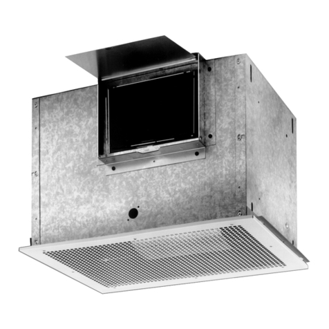
Carnes VCDD210I-330I Inline Cabinet Fan
Operation & Instructions Manual
Page 1
MODELS • VCDD210I•VCDD330I
®
!
WARNING
TO REDUCE THE RISK OF FIRE,ELECTRIC SHOCK,OR IN-
JURYTO PERSONS,OBSERVETHE FOLLOWING:
1.Use this unit only in the manner intended by the manufacturer.If
you have questions, contact the manufacturer at the address or
telephone number listed in the warranty.
2.Beforeservicing orcleaningunit, switchpoweroffat service panel
andlockthe service disconnecting means to prevent power from
being switched on accidentally.When the service disconnecting
means cannot be locked, securely fasten a prominent warning
device, such as a tag, to the service panel.
3.Installation work and electrical wiring must be done by a quali-
fied person(s) in accordance with all applicable codes and stan-
dards, including fire-rated construction codes and standards.
4.Sufficient air is needed for proper combustion and exhausting of
gases through the flue (chimney) of fuel burning equipment to
prevent backdrafting.Follow the heating equipment
manufacturer’s guideline and safety standards such as those
published by the National Fire Protection Association (NFPA),
andtheAmerican Society for Heating, Refrigeration and Air Con-
ditioning Engineers (ASHRAE), and the local code authorities.
5.When cutting or drilling into wall or ceiling, do not damage elec-
trical wiring and other hidden utilities.
6.Ducted fans must always be vented to the outdoors.
7.This unit must be grounded.
CAUTION
1.For general ventilating use only.Do not use to exhaust hazard-
ous or explosive materials and vapors.
2.To avoid motor bearing damage and noisy and/or unbalanced
impellers, keep drywall spray, construction dust, etc.off power
unit.
3.Please read specification label on product for further informa-
tion and requirements.
IN-LINE CABINET
VENTILATORS
READ AND SAVETHESE INSTRUCTIONS
MOUNTING
CHANNELS
Factory shipped ready to be installed as a ceiling
ventilator with right-angle discharge.
MOUNTING
(In-line Configuration)
Converted for in-line applications.
EXHAUST
CEILING
3/8” MIN.
THREADED ROD
(By Others)
ACCESS
PANEL
DUCT
FLANGES INTAKE GRILLE KIT
EXHAUST
3/8” MIN.
THREADED ROD
(By Others)
ACCESS
PANEL
DUCT
FLANGES
ADJUSTABLE
BRACKET
INTAKE
INTAKE
PLAN INSTALLATION
MOUNTING
(Right-angle Discharge)
Carnes VCDD210I-330I Inline Cabinet Fan
Operation & Instructions Manual
#2 Chootoo Road, South Aranguez, San Juan, Trinidad
MODELS • VCDD210I• VCDD330I
Page 2
®
PLAN INSTALLATION (cont.) MOUNTING OPTIONS
CONVERTING FROM RIGHT-ANGLETO IN-LINE
Remove and reverse duct flanges and access panel
positions on housing.
For correct intake and exhaust duct size, see Table 1.
TABLE 1
ACCESS
PANEL
INTAKE DUCT
FLANGES
EXHAUST
DUCT FLANGE
EXHAUST
DUCT FLANGE
Typical mounting with threaded rod through
mounting channels on top of housing.
3/8” MIN.
THREADED RODS
(By Others)
DIM. VCDD210IVCDD330I
C 12-5/8” 12-5/8”
D 39-5/8” 47-3/8”
Mounting with threaded rod through adjustable
mounting brackets located at top of housing.
3/8” MIN. THREADED RODS
(By Others)
DIM. VCDD210IVCDD330I
A 7-3/4” 10-1/4”
B 33-3/4” 41-3/4”
Mounting with threaded rods through adjustable
mounting brackets located at bottom of housing.
Mounting brackets can be bolted to housing ends in a variety of
configurations. Use screws and nuts provided in parts bag.
If installing unit as a ceiling ventilator, make sure that either duct
flanges or housing will be flush with finished ceiling. Duct flanges
may be removed and discarded if they interfere with a ceiling instal-
lation.
MOUNTING OPTIONS
MODEL INTAKE DUCT SIZE EXHAUST DUCT SIZE
VCDD210I12-3/8” x 35-3/4” 7-3/4” x 33-3/4”
VCDD330I14-1/2” x 43-1/2” 9-3/4” x 41-3/8”
Provide solid support to minimize sound leves.There are two basic
mounting methods for these units.
Carnes VCDD210I-330I Inline Cabinet Fan
Operation & Instructions Manual
MODELS • VCDD210I•VCDD330I
Page 2
®
PLAN INSTALLATION (cont.) MOUNTING OPTIONS
CONVERTING FROM RIGHT-ANGLETO IN-LINE
Remove and reverse duct flanges and access panel
positions on housing.
For correct intake and exhaust duct size, seeTable 1.
TABLE 1
ACCESS
PANEL
INTAKE DUCT
FLANGES
EXHAUST
DUCT FLANGE
EXHAUST
DUCT FLANGE
Typical mounting with threaded rod through
mounting channels on top of housing.
3/8”MIN.
THREADED RODS
(By Others)
DIM. VCDD210IVCDD330I
C 12-5/8” 12-5/8”
D 39-5/8” 47-3/8”
Mounting with threaded rod through adjustable
mounting brackets located at top of housing.
3/8” MIN.THREADED RODS
(By Others) DIM. VCDD210IVCDD330I
A 7-3/4” 10-1/4”
B 33-3/4” 41-3/4”
Mounting with threaded rods through adjustable
mounting brackets located at bottom of housing.
Mounting brackets can be bolted to housing ends in a variety of
configurations.Use screws and nuts provided in parts bag.
If installing unit as a ceiling ventilator, make sure that either duct
flanges or housing will be flush with finished ceiling. Duct flanges
may be removed and discarded if they interfere with a ceiling instal-
lation.
MOUNTING OPTIONS
MODEL INTAKE DUCT SIZE EXHAUST DUCT SIZE
VCDD210I12-3/8” x 35-3/4” 7-3/4” x 33-3/4”
VCDD330I14-1/2” x 43-1/2” 9-3/4” x 41-3/8”
Provide solid support to minimize sound leves.There are two basic
mounting methods for these units.
Carnes VCDD210I-330I Inline Cabinet Fan
Operation & Instructions Manual
#2 Chootoo Road, South Aranguez, San Juan, Trinidad
Page 3
MODELS • VCDD210I• VCDD330I
®
WARNING: To reduce the risk of electric shock,
disconnect from power supply before servicing.
To clean grille: Use appropriate vacuum attachment or remove
grille and clean with a soft cloth and mild soap or detergent. Dry
grille thoroughly before reinstalling.
To clean blower assembly: Remove either access panel or ceil-
ing grille. Unplug blower assembly. Provide safe support for blower
assembly. Remove blower mounting screws and lift blower assem-
bly out of housing. Gently vacuum housing and blower motor.
Vacuum or gently wash blower wheels and housings. DO NOT AL-
LOW WATER TO ENTER MOTOR. Make sure blower assembly is
completely dry before reinstalling. Replace blower assembly in hous-
ing and plug assembly in. Replace grille and/or access panel.
Motor is permanently lubricated. Do not oil or disassemble motor.
USE AND CARE
Ventilator is designed for continuous operation. If desired, it may be
controlled using an on/off switch or a solid-state, variable speed
control. Follow wiring instructions packed with control, and adhere
to all local and state codes, and the National Electrical Code.
MOUNTING OPTIONS
EXHAUST
ACCESS
PANEL
INTAKE
SLEEPER
1-1/4”
Typical wall mounting with 3/8” threaded fasteners
(by others) through mounting brackets.
Connect electrical power cable to housing with proper connector
for type of cable used. Provide 6” leads inside wiring box.
ELECTRICAL CONNECTIONS
MOTORMOTOR
MOTOR
MODEL
VCDD330I
MODEL
VCDD210I
SPEED CONTROL
OR SWITCH
SPEED CONTROL
OR SWITCH
LINE IN
120 VAC
60 HZ
LINE IN
240 VAC
60 HZ
1 PHASE
WHITE
GND
BLK
RED
GND
BLK
ACCESSORY INSTALLATIONS
Install damper flap using rod provided.
Snap screw bushings into square openings around intake
opening. Install grille with screws provided.
NOTE: If duct flanges around intake opening interfere with installa-
tion, remove them. Make sure that housing is flush with finished
ceiling when ventilator is mounted.
OUTSIDE
DAMPER BUSHING
(Snaps over rod)
INSIDE DAMPER
BUSHING
(Inside of frame)
DAMPER FLAP
(Should open freely)
CABINET FLUSH
CEILING
GRILLE
NUTS
GRILLE
SCREWS
If ventilator will discharge directly outside, install adamper kit to
prevent backdrafts. A grille kit is available for applications where
ventilator is installed with direct or remote room air intake.
ROD
(Inserts into inside bushing)
DUCT FLANGES
DAMPER GRILLE SPEED VIBRATION
MODEL KIT KIT CONTROL HANGER
VCDD210ID100 G102 72V / 72W V104
VCDD330ID101 G103 75V V104
ACCESSORIES
Carnes VCDD210I-330I Inline Cabinet Fan
Operation & Instructions Manual
Page 3
MODELS • VCDD210I•VCDD330I
®
WARNING: To reduce the risk of electric shock,
disconnect from power supply before servicing.
To clean grille: Use appropriate vacuum attachment or remove
grille and clean with a soft cloth and mild soap or detergent. Dry
grille thoroughly before reinstalling.
To clean blower assembly: Remove either access panel or ceil-
ing grille.Unplug blower assembly.Provide safe support for blower
assembly.Remove blower mounting screws and lift blower assem-
bly out of housing. Gently vacuum housing and blower motor.
Vacuum or gently wash blower wheels and housings.DO NOT AL-
LOW WATER TO ENTER MOTOR. Make sure blower assembly is
completelydry beforereinstalling.Replaceblowerassemblyinhous-
ing and plug assembly in.Replace grille and/or access panel.
Motor is permanently lubricated.Do not oil or disassemble motor.
USE AND CARE
Ventilator is designed for continuous operation.If desired, it may be
controlled using an on/off switch or a solid-state, variable speed
control. Follow wiring instructions packed with control, and adhere
to all local and state codes, and the National Electrical Code.
MOUNTING OPTIONS
EXHAUST
ACCESS
PANEL
INTAKE
SLEEPER
1-1/4”
Typical wall mounting with 3/8” threaded fasteners
(by others) through mounting brackets.
Connect electrical power cable to housing with proper connector
for type of cable used. Provide 6” leads inside wiring box.
ELECTRICAL CONNECTIONS
MOTORMOTOR
MOTOR
MODEL
VCDD330I
MODEL
VCDD210I
SPEED CONTROL
OR SWITCH
SPEED CONTROL
OR SWITCH
LINE IN
120 VAC
60 HZ
LINE IN
240 VAC
60 HZ
1 PHASE
WHITE
GND
BLK
RED
GND
BLK
ACCESSORY INSTALLATIONS
Install damper flap using rod provided.
Snap screw bushings into square openings around intake
opening. Install grille with screws provided.
NOTE: If duct flanges around intake opening interfere with installa-
tion, remove them. Make sure that housing is flush with finished
ceiling when ventilator is mounted.
OUTSIDE
DAMPER BUSHING
(Snaps over rod)
INSIDE DAMPER
BUSHING
(Inside of frame)
DAMPER FLAP
(Should open freely)
CABINET FLUSH
CEILING
GRILLE
NUTS
GRILLE
SCREWS
If ventilator will discharge directly outside, install adamper kit to
prevent backdrafts. A grille kit is available for applications where
ventilator is installed with direct or remote room air intake.
ROD
(Inserts into inside bushing)
DUCT FLANGES
DAMPER GRILLE SPEED VIBRATION
MODEL KIT KIT CONTROL HANGER
VCDD210ID100 G102 72V / 72W V104
VCDD330ID101 G103 75V V104
ACCESSORIES
Carnes VCDD210I-330I Inline Cabinet Fan
Operation & Instructions Manual
#2 Chootoo Road, South Aranguez, San Juan, Trinidad
MODELS •VCDD210I•VCDD330I
Page 4
®
KEYMODEL VCDD210IMODEL VCDD330I
NO. PART NO. QTY. PART NO. QTY. DESCRIPTION
199420466 27 99420466 27 Insulation Clip
299170261 16 99170261 18 #5/16 - 18 x ½
Serrated Hex
Head Screw
398006462 298006462 2Mounting Bracket
497008107 197008108 1Cabinet Body
593260447 12 93260447 14 #5/16 - 18 Lock
Nut
699150471 2---- -- #10-32 x ½ Green
Ground Screw
799150490 42 99150490 44 #10B x 3/8
Serrated Pan
Head Screw
899270658 199270658 1Outlet Box Cover
999160319 299160319 2#6-32 x 3/8
Machine Screw
10 99270656 199270657 1Receptacle
11 99270659 199270659 1Outlet Box
12 98006364 298006376 2Duct Inlet Flange -
short
13 98006363 298006375 2Duct Inlet Flange -
long
14 99500335 299500339 2Bottom Panel
Insulation
15 99500333 199500337 1Back Panel
Insulation
16 99500334 299500338 2End Panel
Insulation
17 98006699 198006700 1Access Panel
18 99500336 199500340 1Access Panel
Insulation
19 97007450 197007451 1Blower Platform
20 98006475 498006476 4 Venturi Ring
21 97007453 197007455 1Right Hand Scroll
22 99020172 199020174 1Blower Wheel -
clockwise
23 99260477 10 99260477 12 ¼-20 Lock Nut
24 98006365 198006377 1Blower Support
Channel
25 99080194 199080195 1Motor
26 98006381 198006382 1Motor Platform
27 99020173 199020175 1Blower Wheel -
counter-clock-
wise
28 97007452 197007454 1Left Hand Scroll
29 G-102 1G-103 Grille Kit (contains
Key Nos. 30, 31
& 32)
30 99420470 899420470 8 Grille Nut
31 98006477 198006478 1Grille
32 99150472 899150472 8#8-18 x 1¼ Grille
Screw
33 D-100 1D-101 1Damper Kit
(contains Key
Nos. 34, 35, 36 &
37)
34 99100379 499100379 4Damper Bushing
35 98006479 298006480 2Damper Flap
36 98006481 298006472 2Damper Rod
37 99760002 299760002 2Damper Flap
Magnet
** 97007448 197007448 1 Parts Bag
(contains 4 ea. of
Key Nos. 2 & 5)
Order replacement parts by PART NO. - not by KEY NO.
** Not Shown
SERVICE PARTS SERVICE PARTS
11241
Carnes VCDD210I-330I Inline Cabinet Fan
Operation & Instructions Manual
MODELS • VCDD210I•VCDD330I
Page 4
®
KEYMODEL VCDD210IMODEL VCDD330I
NO.PART NO.QTY.PART NO.QTY.DESCRIPTION
199420466 27 99420466 27 Insulation Clip
299170261 16 99170261 18 #5/16 - 18 x ½
Serrated Hex
Head Screw
398006462 298006462 2Mounting Bracket
497008107 197008108 1Cabinet Body
593260447 12 93260447 14 #5/16 - 18 Lock
Nut
699150471 2---- -- #10-32 x ½ Green
Ground Screw
799150490 42 99150490 44 #10B x 3/8
Serrated Pan
Head Screw
899270658 199270658 1Outlet Box Cover
999160319 299160319 2#6-32 x 3/8
Machine Screw
10 99270656 199270657 1Receptacle
11 99270659 199270659 1Outlet Box
12 98006364 298006376 2Duct Inlet Flange -
short
13 98006363 298006375 2Duct Inlet Flange -
long
14 99500335 299500339 2Bottom Panel
Insulation
15 99500333 199500337 1Back Panel
Insulation
16 99500334 299500338 2End Panel
Insulation
17 98006699 198006700 1Access Panel
18 99500336 199500340 1Access Panel
Insulation
19 97007450 197007451 1Blower Platform
20 98006475 498006476 4Venturi Ring
21 97007453 197007455 1Right Hand Scroll
22 99020172 199020174 1Blower Wheel -
clockwise
23 99260477 10 99260477 12 ¼-20 Lock Nut
24 98006365 198006377 1Blower Support
Channel
25 99080194 199080195 1Motor
26 98006381 198006382 1Motor Platform
27 99020173 199020175 1Blower Wheel -
counter-clock-
wise
28 97007452 197007454 1Left Hand Scroll
29 G-102 1G-103 Grille Kit (contains
Key Nos.30, 31
& 32)
30 99420470 899420470 8Grille Nut
31 98006477 198006478 1Grille
32 99150472 899150472 8#8-18 x 1¼ Grille
Screw
33 D-100 1D-101 1Damper Kit
(contains Key
Nos.34, 35, 36 &
37)
34 99100379 499100379 4Damper Bushing
35 98006479 298006480 2Damper Flap
36 98006481 298006472 2Damper Rod
37 99760002 299760002 2Damper Flap
Magnet
** 97007448 197007448 1Parts Bag
(contains 4 ea. of
Key Nos.2 & 5)
Order replacement parts by PART NO.- not by KEY NO.
** Not Shown
SERVICE PARTS SERVICE PARTS
11241
Carnes VCDD210I-330I Inline Cabinet Fan
Operation & Instructions Manual
This manual suits for next models

1

Other CARNES Fan manuals

CARNES VCDK040I User manual

CARNES

CARNES VCDK040I User manual

CARNES VFBB Assembly instructions

CARNES

CARNES VFBB Assembly instructions

CARNES VW — BELT Assembly instructions

CARNES

CARNES VW — BELT Assembly instructions

CARNES VRBK User manual

CARNES

CARNES VRBK User manual

CARNES LW/LM Owner's manual

CARNES

CARNES LW/LM Owner's manual

CARNES VCDD040I User manual

CARNES

CARNES VCDD040I User manual

CARNES VCDK090C User manual

CARNES

CARNES VCDK090C User manual

CARNES VCDK040C User manual

CARNES

CARNES VCDK040C User manual

CARNES HXBG User manual

CARNES

CARNES HXBG User manual

CARNES LW/LM Owner's manual

CARNES

CARNES LW/LM Owner's manual

CARNES VCDD090I User manual

CARNES

CARNES VCDD090I User manual

Popular Fan manuals by other brands

motortronics VMX-agility VMX-AGY-030 installation guide

motortronics

motortronics VMX-agility VMX-AGY-030 installation guide

Klarstein Spin Doctor manual

Klarstein

Klarstein Spin Doctor manual

Munters EC52 Manual for use and maintenance

Munters

Munters EC52 Manual for use and maintenance

Black & Decker BXFD52002GB Original instructions

Black & Decker

Black & Decker BXFD52002GB Original instructions

Caframo Maestro 7482CA-WBX operating instructions

Caframo

Caframo Maestro 7482CA-WBX operating instructions

BLAUBERG ISO-RB 100 user manual

BLAUBERG

BLAUBERG ISO-RB 100 user manual

Field Controls 46261700 Replacement instructions

Field Controls

Field Controls 46261700 Replacement instructions

Noaton 13045 Puppis Instructions for use

Noaton

Noaton 13045 Puppis Instructions for use

Vacmaster AM1502 manual

Vacmaster

Vacmaster AM1502 manual

KEEN Smart Vent installation guide

KEEN

KEEN Smart Vent installation guide

durabuild 7SDUB105BLK instruction manual

durabuild

durabuild 7SDUB105BLK instruction manual

Vectaire MBOX204/2 Installation, operating and maintenance instructions

Vectaire

Vectaire MBOX204/2 Installation, operating and maintenance instructions

Home Decorators Collection TRUDEAU YG545A-EB Use and care guide

Home Decorators Collection

Home Decorators Collection TRUDEAU YG545A-EB Use and care guide

AirScape AH2-CF-1600 Installation and operation manual

AirScape

AirScape AH2-CF-1600 Installation and operation manual

IRIS WOOZOO PCF-SDC15T Series instruction manual

IRIS

IRIS WOOZOO PCF-SDC15T Series instruction manual

ALORAIR VentirPro 260 Installation and user manual

ALORAIR

ALORAIR VentirPro 260 Installation and user manual

S&P EDM-300 User instructions

S&P

S&P EDM-300 User instructions

Sharper Image 206635 user guide

Sharper Image

Sharper Image 206635 user guide

manuals.online logo
manuals.online logoBrands
  • About & Mission
  • Contact us
  • Privacy Policy
  • Terms and Conditions

Copyright 2025 Manuals.Online. All Rights Reserved.