manuals.online logo
Brands
  1. Home
  2. •
  3. Brands
  4. •
  5. Carrier
  6. •
  7. Air Conditioner
  8. •
  9. Carrier 48/50P030-100 Dimensions and installation guide

Carrier 48/50P030-100 Dimensions and installation guide

Manufacturer reserves the right to discontinue, or change at any time, specifications or designs without notice and without incurring obligations.
Catalog No. 04-53480064-01 Printed in U.S.A. Form 48/50-73SI Pg 1 8-09 Replaces: 48/50A-4SI
Installation Start-Up and
Service Instructions
Part No. CRCBDIOX002A00
CONTENTS
SAFETY CONSIDERATIONS . . . . . . . . . . . . . . . . . . . . . . 1
GENERAL . . . . . . . . . . . . . . . . . . . . . . . . . . . . . . . . . . . . . . . . 1
Check Package Contents. . . . . . . . . . . . . . . . . . . . . . . . . 1
INSTALLATION . . . . . . . . . . . . . . . . . . . . . . . . . . . . . . . . . .2,3
START-UP . . . . . . . . . . . . . . . . . . . . . . . . . . . . . . . . . . . . . . . . 4
Configuring the ComfortLink™ Controller. . . . . . . . 4
Verification and Calibration . . . . . . . . . . . . . . . . . . . . . . 4
SERVICE . . . . . . . . . . . . . . . . . . . . . . . . . . . . . . . . . . . . . . . . . 4
Cleaning . . . . . . . . . . . . . . . . . . . . . . . . . . . . . . . . . . . . . . . . . 4
TROUBLESHOOTING. . . . . . . . . . . . . . . . . . . . . . . . . . . . . 4
SAFETY CONSIDERATIONS
Installing, starting up and servicing HVAC (heating, ventila-
tion, and air conditioning) equipment can be hazardous due to
system pressures, electrical components and equipment
locations.
Only trained, qualified installers and service technicians
should install, start up and service this equipment.
When working on HVAC equipment, observe precautions
in the literature, labels attached to the equipment and any other
safety precautions that apply. Follow all safety codes. Wear
safety glasses and work gloves. Use care when handling and
installing the sensor.
Understand the signal words DANGER, WARNING, and
CAUTION. These words are used with the safety alert
symbol . DANGER identifies the most serious hazards
which will result in severe personal injury or death.
WARNING signifies a hazard which could result in personal
injury or death. CAUTION is used to identify unsafe practices
which would result in minor personal injury or property
damage.
GENERAL
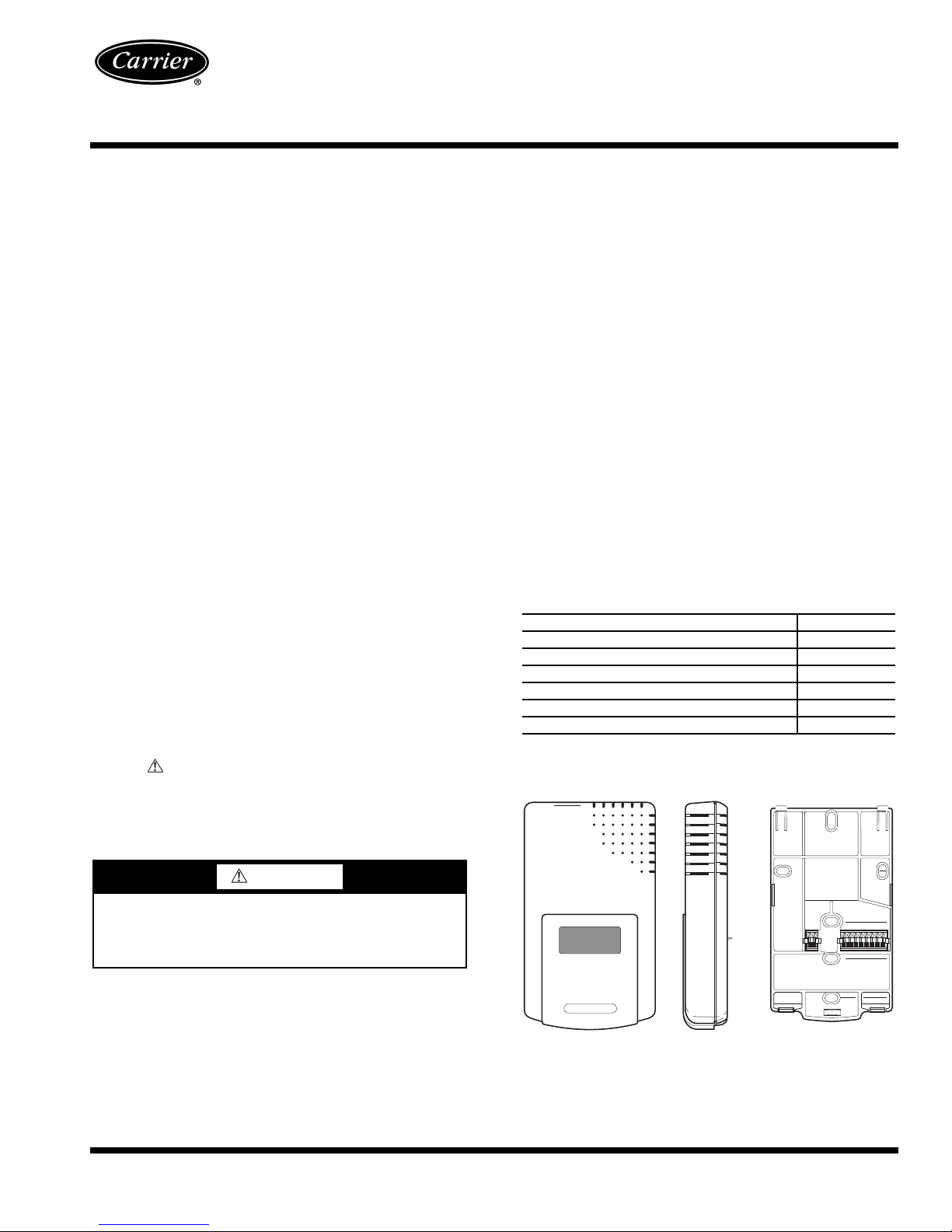
The CO2sensor (Fig. 1) is designed to monitor carbon
dioxide (CO2) levels in the return air and interface with the
ComfortLink™ controller on the rooftop air-conditioning unit.
The sensor perceives CO2levels in the 0 to 2,000 parts per
million (ppm) range and provides outputs indicating this level.
The unit utilizes a 4 to 20-mA analog signal. The ComfortLink
controller uses this signal to control the economizer damper
position and ensure adequate level of outside air in the
building. This is one of several approved methods of control-
ling the indoor-air quality (IAQ) in a building and meets the
requirements of local building codes and ASHRAE (American
Society of Heating, Refrigerating and Air Conditioning
Engineers) Standard 62. The control sensor features a mem-
brane-covered waveguide and sample chamber that produces
stable, reliable, and highly accurate carbon dioxide readings.
The sensor is self-calibrating and should not need to be
manually calibrated.
Check Package Contents — Remove accessory pack-
aging and inspect shipment for damage. If any damage is found,
file a claim with the shipping agent immediately. If any item is
missing or any part does not assemble properly, notify your
Carrier distributor. Table 1 lists the accessory package contents.
Table 1 — Accessory Package Contents
*Do not use the electrical harness provided in this kit for 48/50P and
48/50Z units.
WARNING
Prior to installation of this accessory, make sure all power
is disconnected to the unit and locked out. Failure to dis-
connect power supply prior to servicing may result in seri-
ous injury.
ITEM QUANTITY
CO2Sensor (Part No. HH99ZZ019) 1
Bracket (48/50A) 1
No. 8-18 x 1/4Screw 2
1/4AB-14 x 5/8Screw 2
Electrical Harness* 1
Bracket (48/50P,48/50Z) 1
48/50A020-060, 48/50P030-100,
48/50Z030-105
CO2Sensor Accessory
FRONT VIEW SIDE VIEW MOUNTING PLATE
Fig. 1 — CO2Sensor
2
INSTALLATION
48/50A Units — The CO2sensor is to be installed in the
predrilled holes located above the auxiliary control box (see
Fig. 2).
1. Shut off unit power supply.
2. Open the hinged auxiliary control box access door and
secure.
3. Remove the sensor and cover from the sensor mounting
plate.
4. Secure mounting plate to bracket (48/50A) with no. 8
screws (see Fig. 3).
5. Wire the electrical harness to the sensor as shown in
Fig. 3 and 4.
6. Remove the blankout plate from the partition, just above
the auxiliary control box.
7. Attach the sensor to the mounting plate.
8. Mount the bracket to the partition using 2 sheet metal
screws (see view F in Fig. 2).
9. Connect the electrical harness (PL18).
10. Restore power to unit.
48/50P and 48/50Z Units — The CO2sensor is to be
installed in the predrilled holes located in the power exhaust
section. See Fig. 5-11.
1. Shut off unit power supply.
2. Open the power exhaust section doors/panels to gain
access.
3. Remove the sensor and cover from the sensor mounting
plate.
4. Secure mounting plate to the bracket with no. 8 screws.
5. The electrical wire harness for the CO2sensor is factory
installed. Locate the four wires in the power exhaust
section. Wire the electrical harness to the sensor as shown
in Fig. 4.
6. Attach the sensor to the mounting plate.
Mount the bracket to the appropriate location:
size 030-050 units with power exhaust, see Fig. 5 and 6.
size 030-050 units with economizer only, see Fig. 7.
size 030-050 units with no economizer or power exhaust,
see Fig. 8.
48/50P055-100 and 48/50Z055-105 units with power ex-
haust, see Fig. 9.
48/50P055-100 and 48/50Z055-105 units with economiz-
er only, see Fig. 10.
48/50P055-100 and 48/50Z055-105 units with no econo-
mizer or power exhaust, see Fig. 11.
CO2
SENSOR
AUXILIARY
CONTROL BOX
PARTITION BRACKET
(48/50A)
ELECTRICAL
HARNESS
Fig. 2 — 48/50A CO2Sensor Mounting Location
VIEW F
3
7. Restore power to unit.
CO2SENSOR
AND BRACKET
CO2SENSOR
AND BRACKET
PL18
(48/50A
ONLY)
BRACKET
(48/50A)
SENSOR MOUNTING PLATE
HOLES MUST LINE-UP
COVER SCREW
SENSOR COVER
CO2SENSOR
AND BRACKET
CO2SENSOR
AND
BRACKET
CO2SENSOR
AND BRACKET
Fig. 7 — CO2Bracket for 48/50P030-050 and
48/50Z030-050 Units (Economizer Only)
Fig. 6 — CO2Bracket for 48/50P030-050 and
48/50Z030-050 Units Side View (Economizer with
Power Exhaust)
Fig. 3 — CO2Sensor Assembly
Fig. 4 — Harness Wiring Connections
Fig. 5 — CO2Bracket for 48/50P030-050 and
48/50Z030-050 Units (Economizer with Power
Exhaust) Fig. 8 — CO2Bracket for 48/50P030-050 and
48/50Z030-050 Units (No Economizer or Power
Exhaust)
Manufacturer reserves the right to discontinue, or change at any time, specifications or designs without notice and without incurring obligations.
Catalog No. 04-53480064-01 Printed in U.S.A. Form 48/50-73SI Pg 4 8-09 Replaces: 48/50A-4SI
Copyright 2009 Carrier Corporation
START-UP
After applying power, the CO2 sensor will enter a warm-up
mode. Warm-up duration will be from 1 to 10 minutes. The
warm-up duration will be shorter in warmer temperatures and
longer in cooler temperatures. During warm-up, the signal
output will be 4 mA. Once the unit has warmed up, the voltage
or current output will be set up to indicate the CO2 level. The
display will show a steady reading 1 minute later.
Configuring the ComfortLink™ Controller —
The CO2 sensor is defaulted to provide 4 mA at 0 ppm and
20 mA at 2000 ppm. If a different range is necessary, contact
Carrier Application Engineering to reconfigure the sensor. If
the sensor is reconfigured, the mA range on the ComfortLink
controller must be configured to match the new values. Refer
to Controls and Troubleshooting Guide for configuration
details.
Sensor Self Calibration — The CO2sensors employ a
self-calibration system. The system eliminates the need for
manual calibration in applications where the indoor CO2level
drops to outside levels during unoccupied periods (e.g., during
evening hours). A special software routine in the sensor re-
members the background readings for 14 consecutive eve-
nings, calculates if there is a sensor drift, and then corrects for
it.
NOTE: This only applies when used in typical indoor or ambi-
ent air conditions. Consult Carrier application engineering if
other gases or corrosive agents are part of the application
environment.
SERVICE
Cleaning — The controller is a rugged and lightweight unit
that requires very little maintenance. Clean external surfaces
periodically with a dampened cloth.
TROUBLESHOOTING
The following occurrences may indicate abnormal opera-
tion, caused primarily by power input fluctuations, surges, or
spikes.
• The unit remains in warm-up mode for more than
10 minutes.
• The LED glows with no pulse.
•CO
2indication (display numbers or signal output) is
frozen.
• Numbers on the display change continuously for longer
than 1 minute.
Normal operation can usually be restored by removing
power, shutting down the unit for at least 15 seconds, then
reconnecting power. The unit should warm up, as described
above, then return to normal operation. If the situation
continues, remove and replace the sensor.
CO2SENSOR
AND BRACKET
CO2SENSOR
AND BRACKET
Fig. 10 — CO2Bracket for 48/50P055-100 and
48/50Z055-105 Units (Economizer Only)
Fig. 11 — CO2Bracket for 48/50P055-100 and
48/50Z055-105 Units (No Economizer or Power
Exhaust)
Fig. 9 — CO2Bracket for 48/50P055-100 and
48/50Z055-105 Units (Economizer with Power
Exhaust)
CO2SENSOR
AND BRACKET

This manual suits for next models

1

Other Carrier Air Conditioner manuals

Carrier 38MHRC User manual

Carrier

Carrier 38MHRC User manual

Carrier 40MHH User manual

Carrier

Carrier 40MHH User manual

Carrier 48ES Instruction Manual

Carrier

Carrier 48ES Instruction Manual

Carrier WeatherMaker 50TC07 Series User manual

Carrier

Carrier WeatherMaker 50TC07 Series User manual

Carrier 38LUVH025N-1 User manual

Carrier

Carrier 38LUVH025N-1 User manual

Carrier 38AH024-034 Dimensions and installation guide

Carrier

Carrier 38AH024-034 Dimensions and installation guide

Carrier 24ANA1 Infinity Quick start guide

Carrier

Carrier 24ANA1 Infinity Quick start guide

Carrier 50SD User manual

Carrier

Carrier 50SD User manual

Carrier 38MAQB12-1 User manual

Carrier

Carrier 38MAQB12-1 User manual

Carrier 48TFD008-014 Quick guide

Carrier

Carrier 48TFD008-014 Quick guide

Carrier GA5S User manual

Carrier

Carrier GA5S User manual

Carrier 50FC 08-16 Series Installation and user guide

Carrier

Carrier 50FC 08-16 Series Installation and user guide

Carrier 38GF Dimensions and installation guide

Carrier

Carrier 38GF Dimensions and installation guide

Carrier 42QHF009DS seires User manual

Carrier

Carrier 42QHF009DS seires User manual

Carrier Air V User manual

Carrier

Carrier Air V User manual

Carrier WeatherExpert 48N2 User guide

Carrier

Carrier WeatherExpert 48N2 User guide

Carrier 38C Series User manual

Carrier

Carrier 38C Series User manual

Carrier 42n User manual

Carrier

Carrier 42n User manual

Carrier 48KHA Dimensions and installation guide

Carrier

Carrier 48KHA Dimensions and installation guide

Carrier 38AE Dimensions and installation guide

Carrier

Carrier 38AE Dimensions and installation guide

Carrier 48FC Series User guide

Carrier

Carrier 48FC Series User guide

Carrier Holiday green 51AKB 006G User manual

Carrier

Carrier Holiday green 51AKB 006G User manual

Carrier Integra 35X User manual

Carrier

Carrier Integra 35X User manual

Carrier 42QZL048DS-1 User manual

Carrier

Carrier 42QZL048DS-1 User manual

Popular Air Conditioner manuals by other brands

Daikin R-410A Technical manual

Daikin

Daikin R-410A Technical manual

Mitsubishi Heavy Industries DXK05ZTLA-WF user manual

Mitsubishi Heavy Industries

Mitsubishi Heavy Industries DXK05ZTLA-WF user manual

Honeywell CL30XC owner's manual

Honeywell

Honeywell CL30XC owner's manual

Mitsubishi Electric PLA-M100EA installation manual

Mitsubishi Electric

Mitsubishi Electric PLA-M100EA installation manual

Kaden KCS Series manual

Kaden

Kaden KCS Series manual

Mitsubishi Electric MSZ-DM25VA operating instructions

Mitsubishi Electric

Mitsubishi Electric MSZ-DM25VA operating instructions

Sanyo STB0811C1-S parts list

Sanyo

Sanyo STB0811C1-S parts list

York DJ 300 Technical guide

York

York DJ 300 Technical guide

Admiral AW-05CM1FLU use and care manual

Admiral

Admiral AW-05CM1FLU use and care manual

Mitsubishi Electric NTXFKs15a112a Series manual

Mitsubishi Electric

Mitsubishi Electric NTXFKs15a112a Series manual

Sharp AU-1802Y Operation manual

Sharp

Sharp AU-1802Y Operation manual

Mitsubishi Electric City Multi Series Technical & service manual

Mitsubishi Electric

Mitsubishi Electric City Multi Series Technical & service manual

Nortek AB 225 Installation and operating manual

Nortek

Nortek AB 225 Installation and operating manual

Crosley CAE10MR410A13 use & care

Crosley

Crosley CAE10MR410A13 use & care

Trane 4TCA4024A1000A Installer's guide

Trane

Trane 4TCA4024A1000A Installer's guide

GD Midea Refrigeration Equipment Elite Series Technical & service manual

GD Midea Refrigeration Equipment

GD Midea Refrigeration Equipment Elite Series Technical & service manual

Dettson COND-UHD-09 Installation instructions and homeowner's manual

Dettson

Dettson COND-UHD-09 Installation instructions and homeowner's manual

Samsung MH18VP2-09 Owner's instructions

Samsung

Samsung MH18VP2-09 Owner's instructions

manuals.online logo
manuals.online logoBrands
  • About & Mission
  • Contact us
  • Privacy Policy
  • Terms and Conditions

Copyright 2025 Manuals.Online. All Rights Reserved.