4
The 30XAV Aquaforce units are designed to cool water for
the air conditioning of buildings and industrial processes.
Prior to the initial start-up of the 30XAV units, the people
involved in the on-site installation, start-up, operation, and
maintenance of this unit should be thoroughly familiar with
these instructions and the specific project data for the
installation site.
The 30XAV liquid chillers are designed to provide a very high
level of safety during installation, start-up, operation and
maintenance. They will provide safe and reliable service if
used within their application range.
They are designed for an operating life of 15 years by
assuming a 75% utilisation factor; that is approximately
100,000 operating hours.
Always ensure that all required safety measures are followed,
including those in this document, such as: wearing protective
clothing (gloves, ear defenders, safety glasses and shoes), using
appropriate tools, employing qualied and skilled technicians
(electricians, refrigeration engineers) and following local
regulations.
To find out, if these products comply with European
directives (machine safety, low voltage, electromagnetic
compatibility, equipment under pressure etc.) check the
declarations of conformity for these products.
Access to the unit must be restricted to authorised personnel,
trained and qualified in monitoring and maintenance
procedures. Access limitation is the responsibility of the
customer.
After the unit has been received, when it is ready to be
installed or reinstalled, and before it is started up, it must be
inspected for damage. Check that the refrigerant circuit(s)
is (are) intact, especially that no components or pipes have
shifted (e.g. following a shock). If in doubt, carry out a leak
tightness check and verify with the manufacturer that the
circuit integrity has not been impaired. If damage is detected
upon receipt, immediately le a claim with the shipping
company.
Carrier strongly recommends employing a specialised
company to unload the machine.
Do not remove the skid or the packaging until the unit is
in its nal position. These units can be moved with a fork
lift truck, as long as the forks are positioned in the right
place and direction on the unit.
The units can also be lifted with slings, using only the
designated lifting points marked on the unit.
Use slings with the correct capacity, and always follow the
lifting instructions on the certied drawings supplied with
the unit.
Safety is only guaranteed, if these instructions are carefully
followed. If this is not the case, there is a risk of failure and
injuries to personnel.
DO NOT COVER ANY PROTECTION DEVICES. This
applies to fuse plugs and relief valves (if used) in the
refrigerant or heat transfer medium circuits. Check if the
original protection plugs are still present at the valve outlets.
These plugs are generally made of plastic and should not be
used. If they are still present, please remove them. Install
devices at the valve outlets or drain piping that prevent the
penetration of foreign bodies (dust, building debris, etc.) and
atmospheric agents (water can form rust or ice). These
devices, as well as the drain piping, must not impair
operation and not lead to a pressure drop that is higher than
10% of the control pressure.
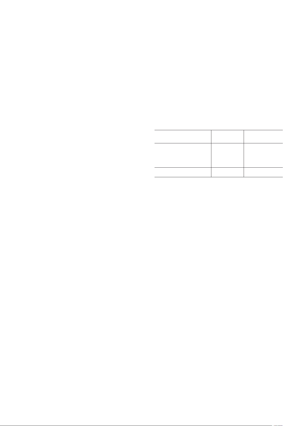
Classication and control:
In accordance with the Pressure Equipment Directive and
national usage monitoring regulations in the European
Union, the protection devices when tted to these machines
are classied as follows:
High-pressure switch X
External relief valve*** X
Rupture disk X
Fuse plug X
External relief valve**** X X
* Classiedforprotectioninnormalservicesituations.
** Classiedforprotectioninabnormalservicesituations.
*** The instantaneous over-pressure limited to 10% of the operating pressure does not apply
tothisabnormalservicesituation.Thecontrolpressurecanbehigherthantheservice
pressure.Inthiscaseeitherthedesigntemperatureorthehigh-pressureswitchensures
thattheservicepressureisnotexceededinnormalservicesituations.
**** Theclassicationofthesereliefvalvemustbemadebythepersonnelthatcompletesthe
wholehydronicinstallation.
Do not remove valves / fusible plugs, even if the re risk is
under control for a particular installation. There is no
guarantee that the accessories are re-installed if the
installation is changed or for transport with a gas charge.
When the unit is subjected to re, safety devices prevent
rupture due to over-pressure by releasing refrigerant. The
uid may then be decomposed into toxic residues when
subjected to the ame:
• Stay away from the unit.
• Set up warnings and recommendations for personnel
in charge to stop the re.
• Fire extinguishers appropriate to the system and the
refrigerant type must be easily accessible.
All factory -installed relief valves are lead-sealed to prevent
any calibration change. The external relief valves must
always be connected to vent pipes for units installed in a
closed room. Refer to the installation regulations, for
example those of European standard EN 378 and EN 13136.
These pipes must be installed in a way that ensures that
people and property are not exposed to vented refrigerant.
As the uids can be diffused in the air, ensure that refrigerant
is discharged away from building air intakes, relief valves
must be checked periodically. See paragraph “Maintenance
safety considerations”
Provide a drain in the vent pipe, close to each relief valve, to
avoid an accumulation of condensate or rain water.
All precautions concerning handling of refrigerant must be
observed in accordance with local regulations.