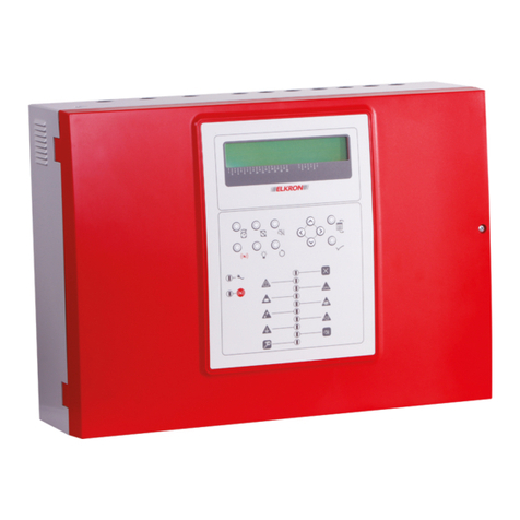
Carrier 2X-A/2X User manual

UC240 UltraSync
Communicator Installation
Guide for
2X-A/2X, KFP-
A,
and ZP2
-A/ZP2
Fire Alarm
Control Panels
P/N 10-9000-501-UC24-02 • ISS 17NOV22

Copyright
©
2022 Carrier. All rights reserved.
Trademarks and
patents
UC240 UltraSync Communicator
is a trademark of Carrier.
Other trade names used in this document may be trademarks or
registered trademarks of the manufacturers or vendors of the
respective
products.
Manufacturer
Authorized EU manufacturing representative:
Carrier Fire & Security B.V.,
Kelvinstraat 7, 6003 DH Weert, Netherlands.
Product warnings and
disclaimers
THESE PRODUCTS ARE INTENDED FOR SALE TO AND
INSTALLATION BY
QUALIFIED PROFESSIONALS.
CARRIER
FIRE & SECURITY B.V. CANNOT PROVIDE ANY
ASSURANCE THAT ANY PERSON OR ENTITY BUYING ITS
PRODUCTS, INCLUDING ANY “AUTHORIZED DEALER” OR
“AUTHORIZED RESELLER”, IS PROPERLY TRAINED OR
EXPERIENCED TO CORRECTLY INSTALL FIRE AND SECURITY
RELATED PRODUCTS.
For more information on war
ranty disclaimers and product safety
information, please check
https://firesecurityproducts.com/policy/
product
-warning/ or scan the QR code.
Contact information
and product
document
ation
For contact information or to download the latest product
documentation, visit
firesecurityproducts.com.
Conformity
2012/19/EU (WEEE Directive): Products marked with this symbol
cannot be disposed of as unsorted municipal waste in the European
Union. For proper recycling, return this product to your local supplier
upon the purchase of equivalent new equipment, or dispos
e of it at
designated collection points. For more information see:
recyclethis.info
.
2006/66/EC (
Battery Directive): This product contains a battery that
cannot be disposed of as unsorted municipal waste in
the European
Union. See the product documentation for specific battery
information. The battery is marked with this symbol, which may
include lettering to indicate cadmium (Cd), lead (Pb), or
mercury
(Hg). For proper recycling, return the battery to your s
upplier
or to a designated collection point. For more information see:
recyclethis.info
.

UC240 UltraSync Communicator Installation Guide for 2X-A/2X, KFP-A, and ZP2-A/ZP2 Fire Alarm Control Panels i
Content
Important information ii
Limitation of liability ii
Advisory messages ii
Installation 1
Scope 1
Description 1
Installation 2
Wiring 5
Control panel configuration and UC240 programming 7
Control panel configuration 7
UC240 quick programming guide 8
UC240 commissioning checklist 11
Mapping events 12

ii UC240 UltraSync Communicator Installation Guide for 2X-A/2X, KFP-A, and ZP2-A/ZP2 Fire Alarm Control Panels
Important information
Limitation of liability
To the maximum extent permitted by applicable law, in no event will Carrier be
liable for any lost profits or business opportunities, loss of use, business
interruption, loss of data, or any other indirect, special, incidental, or
consequential damages under any theory of liability, whether based in contract,
tort, negligence, product liability, or otherwise. Because some jurisdictions do not
allow the exclusion or limitation of liability for consequential or incidental
damages the preceding limitation may not apply to you. In any event the total
liability of Carrier shall not exceed the purchase price of the product. The
foregoing limitation will apply to the maximum extent permitted by applicable law,
regardless of whether Carrier has been advised of the possibility of such
damages and regardless of whether any remedy fails of its essential purpose.
Installation in accordance with this manual, applicable codes, and the instructions
of the authority having jurisdiction is mandatory.
While every precaution has been taken during the preparation of this manual to
ensure the accuracy of its contents, Carrier assumes no responsibility for errors
or omissions.
Advisory messages
Advisory messages alert you to conditions or practices that can cause unwanted
results. The advisory messages used in this document are shown and described
below.
WARNING: Warning messages advise you of hazards that could result in injury
or loss of life. They tell you which actions to take or to avoid in order to prevent
the injury or loss of life.
Caution: Caution messages advise you of possible equipment damage. They tell
you which actions to take or to avoid in order to prevent the damage.
Note: Note messages advise you of the possible loss of time or effort. They
describe how to avoid the loss. Notes are also used to point out important
information that you should read.
UC240 UltraSync Communicator Installation Guide for 2X-A/2X, KFP-A, and ZP2-A/ZP2 Fire Alarm Control Panels 1
Installation
Scope
This document describes the installation of the UC240 UltraSync Communicator
for Carrier 2X-A/2X, KFP-A, and ZP2-A/ZP2 fire alarm control panels.
Although the UC240 supports multiple interfaces to fire alarm panels, this
document will focus on the hardware interface only – the dial capture and serial
interfaces are not discussed and their use is not recommended at this time.
As the UC240 is not sold in the United Kingdom, information in this document is
not applicable for UK customers.
Note: For all other information on the UC240 UltraSync Communicator, including
interface connections, programming, and technical specifications – refer to the
UC140/UC240 UltraSync Communicator Installation Sheet (P/N 466-5558-EN
REV A or later).
Description
The UC240 UltraSync Communicator is a dual path (IP and SIM 4G/2G mobile
technology) alarm signalling unit for transmitting signals from a customer’s fire
alarm control panel to a central monitoring station via the Carrier UltraSync
secure transmission system.
Once registered with the Carrier UltraSync portal, the UC240 allows notifications
to be sent to:
• Central Monitoring Stations (CMS)
• Email addresses
• Supported mobile apps (IOS and Android)
Figure 1: UC240 Communicator

2 UC240 UltraSync Communicator Installation Guide for 2X-A/2X, KFP-A, and ZP2-A/ZP2 Fire Alarm Control Panels
Installation
Before installation
The UC240 must first be registered with the Carrier UltraSync portal to operate to
send notifications.
UC240 installation location
The UC240 UltraSync Communicator should be installed in a separate enclosure
immediately adjacent to the fire alarm control panel (this is required as there is
no dual path for the power supply to the device).
Note: We recommend using the SMB-DIN2 enclosure to house the UC240
(included with the UC240 in 2010-2-UC240-KIT).
Install the UC240 onto the underside of the SMB-DIN2 lid using the adhesive
strips provided (see Figure 5 on page 4).
The wireless aerial should be mounted outside the SMB-DIN2 enclosure,
entering the enclosure via a gland.
See “Installation examples” on page 4 for example installation figures.
UC240 wiring
Caution: Fire rated cable is recommended for all interface wiring between the
fire alarm control panel and the UC240. Fire rated IP cabling must be used to
connect the UC240 to the local site LAN.
See “Wiring” on page 5 for wiring connection diagrams.
The SMB-DIN2 enclosure should be connected via a mechanical gland to the fire
alarm control panel to provide mechanical protection for the cabling between the
panel and the UC240.
All cables should be fed into the SMB-DIN2 via glands or conduits.
If direct glanding is not possible, interface cables should be enclosed in conduits
to provide mechanical protection.
Once all wiring is completed, secure the lid to the SMB-DIN2 using the screws
provided.

UC240 UltraSync Communicator Installation Guide for 2X-A/2X, KFP-A, and ZP2-A/ZP2 Fire Alarm Control Panels 3
System wiring
The following wiring options with and without EN 54-21 compliance are available.
Table 1: System wiring options
EN 54
-21 compliant Description Compatible control panels
Yes
Fire routing relay output via
2010-2-PIB board as output to
the UC240.
Large cabinet 2X-A/2X, KFP-A, ZP2-
A/ZP2 control panels with fire routing
and fire protection controls (FB2, FB
models).
No
Event reporting only – Fire
relay output to the UC240.
Any 2X-A/2X, KFP-A, ZP2-A/ZP2
control panel variant.
See “Wiring” on page 5 for wiring connection diagrams for each option.
Configuration and programming
The device can be programmed via the device interface or the UltraSync+ mobile
app (available for Android and IOS mobile devices).
See “Configuration Utility configuration and UC240 programming” on page 7 for
information on configuration and programming.

4 UC240 UltraSync Communicator Installation Guide for 2X-A/2X, KFP-A, and ZP2-A/ZP2 Fire Alarm Control Panels
Installation examples
Figure
2: SMB-DIN2 enclosure
Figure 3: SMB-DIN2 lid screws
Figure
4: UC240 installation (DIN rail)
Figure 5: UC240 installation (inside lid)
Figure
6: UC240 installation location
Figure 7: UC240 installation location

UC240 UltraSync Communicator Installation Guide for 2X-A/2X, KFP-A, and ZP2-A/ZP2 Fire Alarm Control Panels 5
Wiring
EN 54-21 compliant option (2010-2-PIB with fire routing delay)
This option is only compatible with large cabinet control panels with fire routing
and fire protection controls (FB, FB2 models). A 2010-2-PIB Peripherals Interface
Board is required (not supplied).
Figure 8: EN 54-21 compliant option (2010-2-PIB)
Notes:
• The 2010-2-PIB REL1 relay must be set to normally open (NO) – this requires
the relay jumper configuration to be changed from the default switched relay
output setting (see the 2010-2-PIB Peripherals Interface Board Installation
Sheet for more details).
• See Figure 9 on page 6 for interfacing fault input.
• See “Fire routing delay configuration for the 2010-2-PIB” on page 8 for fire
routing delay configuration.
PIB Board
24VDC
3k3
10k0
PIB Board-closeup with Relay1
Fire rou�ng Relay

6 UC240 UltraSync Communicator Installation Guide for 2X-A/2X, KFP-A, and ZP2-A/ZP2 Fire Alarm Control Panels
Non-EN 54-21 compliant option: Panel inputs, fire and fault relay outputs
Event reporting only. This option is compatible with any 2X-A/2X, KFP-A, ZP2-
A/ZP2 control panel variant.
Figure 9: Non-EN 54-21 compliant option (panel inputs, fire and fault relay outputs)

UC240 UltraSync Communicator Installation Guide for 2X-A/2X, KFP-A, and ZP2-A/ZP2 Fire Alarm Control Panels 7
Configuration Utility configuration and
UC240 programming
Configuration Utility configuration
Programmable inputs
Configure the control panel programmable inputs as shown below.
For EN 54-21 compliant installations, configure programmable inputs 1 and 2.
For non-EN 54-21 compliant installations, only input 1 can be configured.
Table 2: Input 1 (for EN 54-21 and non-EN 54-21 installations)
Parameter
Configuration
OpMode
External Fault
Control
Enabled
Description
UltraSync Dialer Fault
Zone
None
Figure 10: Configuration Utility Input 1 configuration
Table 3: Input 2 (only for EN 54-21 installations)
Parameter
Configuration
OpMode
Fire Routing Ack Type 1
Control
Enabled
Description
Dialer/CMS Ack
Zone
None
Figure 11: Configuration Utility Input 2 configuration

8 UC240 UltraSync Communicator Installation Guide for 2X-A/2X, KFP-A, and ZP2-A/ZP2 Fire Alarm Control Panels
Fire routing delay configuration for the 2010-2-PIB
Note: This option is only available for EN 54-21 compliant installations.
First configure the 2010-2-PIB relay 1 (Panel Outputs > PIB Relays) as shown
below.
Figure 12: Configuring the 2010-2-PIB relay
Next configure the required fire routing delay (in seconds) in the Zone
Configuration window (Group ID 971), as shown below. The delay must be
configured for each zone.
Figure 13: Configuring the fire routing delay in the Zone Configuration window

UC240 UltraSync Communicator Installation Guide for 2X-A/2X, KFP-A, and ZP2-A/ZP2 Fire Alarm Control Panels 9
UC240 quick programming guide
First ensure that the unit is registered in the UltraSync Portal.
Use the ↑(up) and ↓(down) buttons to navigate the menu and the ↵(Enter)
button to confirm a selection.
1. Power up the unit.
Before proceeding, wait 5 minutes to ensure that both paths are registered on
the network.
2. Press ↵for three seconds.
3. Go to Config > Inputs > Pin Learn and hold down the ↵for 3 seconds to save.
4. Go to Network > Web-Pass Code (this must be 8 digits)
5. Go to Output Type and change the Output3 setting to Fire Ack. Press ↵for 3
seconds to save.
6. Write down your SID number and Web Pass Code in a safe place.
Figure 14: Web pass code location

10 UC240 UltraSync Communicator Installation Guide for 2X-A/2X, KFP-A, and ZP2-A/ZP2 Fire Alarm Control Panels
Figure 15: Programming menus
Figure 16: Signal strength

UC240 UltraSync Communicator Installation Guide for 2X-A/2X, KFP-A, and ZP2-A/ZP2 Fire Alarm Control Panels 11
UC240 commissioning checklist
Figure 17: Path: Mobile Registered
Figure 18: Mobile1 Strength
Figure
19: Mobile1 Operator
Figure 20: Service Grade
Figure
21: Path: Ethernet Registered

12 UC240 UltraSync Communicator Installation Guide for 2X-A/2X, KFP-A, and ZP2-A/ZP2 Fire Alarm Control Panels
Mapping events
By default the UC240 Communicator reports events as if it is connected to an
intrusion alarm panel. The events received at the central monitoring station
(CMS) shown in the table below must be mapped to the CMS automation
software to indicate Fire Alarm events instead of the default Burglar Alarm events
The Mapping column provides information on the proposed reporting codes to
emulate.
Table 4: Mapping alarm reporting from a fire alarm control panel
Item
Panel Test Event Input to
UC240
Transmission
Path
CMS
Setting in
Portal
CMS
Event
Received
Mapping
1
2X/2X-A,
KFP-A, or
ZP2/ZP2-
A
Fire Alarm PIN 1 IP Surgard CID E323901
R323901
E323901
should be
E110901
(Fire Alarm).
R323901
should be
R110901
(Restoral).
2
SIM 2/4G
3
IP Surgard SIA BA901
BR901
BA901
Should be
FA901 (Fire
Alarm).
BR901
Should be
FR901
(Restoral).
4
SIM 2/4G
5
Fault PIN 8 IP Surgard CID E323908
R323908
E323908
should be
E300908
(System
Trouble).
R323908
should be
R300908
(Alarm
Relay).
6
SIM 2/4G
7
IP Surgard SIA BA908
BR908
BA908
Should be
FT908 (Fire
Trouble).
BR908
Should be
FR908 (Fire
Restoral).
8
SIM 2/4G

This manual suits for next models
3
Table of contents
Other Carrier Control Panel manuals

Carrier
Carrier INFINITY ZONING CONTROL User manual

Carrier
Carrier SmartVu control User manual

Carrier
Carrier Touch Pilot 30XW-V User manual

Carrier
Carrier Aritech Reliance XR Series Installation guide

Carrier
Carrier SmartVu control User manual

Carrier
Carrier HumidiTrac Setup guide

Carrier
Carrier Infinity SYSTXCCUID01-B User manual

Carrier
Carrier Touch Pilot Junior User manual