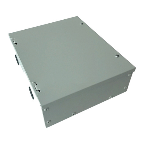
Carrier CSM Operating instructions

Manufacturer reserves the right to discontinue, or change at any time, specifications or designs without notice and without incurring obligations.
PC 111 Catalog No. 533-396 Printed in U.S.A. Form 33CN-1T Pg 1 1202 11-02 Replaces: New
Book 1 4
Tab 11a 13a
Controls Operation and
Troubleshooting Instructions
CONTENTS
Page
GENERAL . . . . . . . . . . . . . . . . . . . . . . . . . . . . . . . . . . . . . . . . 1
CONTROLS . . . . . . . . . . . . . . . . . . . . . . . . . . . . . . . . . . . . . . 1
INSTALLATION CONSIDERATIONS . . . . . . . . . . . . . 1-5
Default Address and Baud Rate . . . . . . . . . . . . . . . . . . 1
Input Wiring . . . . . . . . . . . . . . . . . . . . . . . . . . . . . . . . . . . . . . 3
Output Wiring . . . . . . . . . . . . . . . . . . . . . . . . . . . . . . . . . . . . 3
I/O Type Switch Settings . . . . . . . . . . . . . . . . . . . . . . . . . 5
CONFIGURATION TABLES . . . . . . . . . . . . . . . . . . . . .5-11
Alarm Service Configuration . . . . . . . . . . . . . . . . . . . . . 5
Service Configuration . . . . . . . . . . . . . . . . . . . . . . . . . . . . 5
Time Broadcast Configuration . . . . . . . . . . . . . . . . . . . 7
Holiday Configuration Screens. . . . . . . . . . . . . . . . . . . 8
Time Schedule Configuration . . . . . . . . . . . . . . . . . . . . 8
Points Display Table. . . . . . . . . . . . . . . . . . . . . . . . . . . . . . 9
Occupancy Maintenance Table . . . . . . . . . . . . . . . . . . . 9
CSM III INTERFACE REQUIREMENTS . . . . . . . . .11,12
Chiller Status . . . . . . . . . . . . . . . . . . . . . . . . . . . . . . . . . . . 11
CCN Control Variables . . . . . . . . . . . . . . . . . . . . . . . . . . 12
CONTROL ALGORITHMS. . . . . . . . . . . . . . . . . . . . . .12,13
Control Modes (Shutdown/Local/
CCN/Stand-Alone) . . . . . . . . . . . . . . . . . . . . . . . . . . . . 12
Chiller Start/Stop Function . . . . . . . . . . . . . . . . . . . . . . 12
Chilled Water Set Point Reset Function . . . . . . . . . 13
Demand Limit Function . . . . . . . . . . . . . . . . . . . . . . . . . 13
Alarm Processing . . . . . . . . . . . . . . . . . . . . . . . . . . . . . . . 13
GENERAL
The CSM Chiller Interface allows chillers not manufactured
by Carrier and older Carrier chillers to communicate over a
Carrier Comfort Network (CCN) in order to become part of a
system controlled by a Chiller System Manager III (CSM III).
NOTE: The CSM Chiller Interface is NOT compatible with
the Flotronic™ System Manager.
The CSM Chiller Interface provides hardwired control of
chillers using industry standard I/O methods, such as thermistor
sensor inputs, discrete outputs driving field-supplied relays, and
0 to 10 vdc or 4 to 20 mA control signals. The CSM III supports
a service function (CCN/Local) to allow a chiller to be run
under local control without disturbing the overall control
system. Stand-alone control functions are enabled if CSM III
communications fail. The Chiller Interface provides alarm
messages, display tables, and configuration tables that are
compatible with standard CCN interfaces.
The Chiller Interface can be installed on centrifugal com-
pressor, screw compressor, and reciprocating compressor
chillers manufactured by Carrier, Trane, York, McQuay, and
others, providing those chillers meet the Chiller Interface’s I/O
requirements. One Chiller Interface is required for each indi-
vidual chiller. A pictorial representation of the CSM III/Chiller
Interface system is shown in Fig. 1.
CONTROLS
The Chiller Interface provides the following functions:
• allows a non-CCN equipped chiller to participate in a
multiple chiller system with CSM III (up to 8 chillers)
• provides chiller start/stop, chilled water reset, and
demand limiting control functions
• provides a Time Schedule backup mode for local control
and in the event of CSM III communication failure
(stand-alone mode)
• provides CCN user access (through configuration and
display screens) and CCN alarm messages
• provides adjustable communications baud rate from
9600 (default) to 38,400 bps
The Chiller Interface must be installed on the same CCN
bus as the CSM III. The pump control must be provided by the
native chilled water plant controls and is not provided by the
CSM Chiller Interface.
Chillers to which the Chiller Interface is connected must
support specific input types such as contact closure for chiller
start/stop, and 0 to 10 vdc or 4 to 20 mA inputs for chilled
water set point reset and demand limiting.
The Chiller Interface consists of an outdoor rated version of
the Comfort Controller 1600 module (CC1600) with special-
ized software. The module is connected to the CCN (Level II
Bus) through its primary communication port (RS-485). The
module’s I/O channels are connected to the native chiller con-
troller and to sensors installed at the chiller.
INSTALLATION CONSIDERATIONS
The Chiller Interface is field-installed in a standard CCN
enclosure and powered from a standard CCN power supply.
All installations must comply with local wiring codes.
The Chiller Interface can be returned to its factory configu-
ration by installing a LID cable jumpered between CCN RJ-11
and I/O RJ-11 and cycling power. To perform a reset, the
Chiller Interface must be disconnected from the CCN bus.
Also, the CCN address will default back to 0, 1.
Figure 2 shows the location of the power connector.
Figure 3 shows the location of the communication connector.
Default Address and Baud Rate — The CSM Chiller
Interface’s default address is 0,99 (bus number, system element
number). Default baud rate is 9600 bps. The address and baud
rate can be set using Address Search in Network Service Tool IV
or Service Pack.
Carrier Comfort Network
CSM Chiller Interface
2
CSM III Chiller Interface
Native Chiller Control
Chiller-Mounted Sensors
Service Switch
- current transducer
- LCW/ECW (optional)
Local/CCN Discrete Input
- accepts dry contact start/stop
- accepts % reset signal
- accepts % demand limit signal
- provides safety input
- provides recycle input
- calculates/stores Chiller Data Table
- sets CHIL_S_S Discrete Output
- calculates reset output
based on LCW_STPT
- calculates demand output
based on DEM_LIM
- time schedule backup
- reads Chiller Data Table
- writes CHIL_S_S
- writes LCW_STPT
- writes DEM_LIM
Pin Power
Number Connector
3 24 Vac (+)
2 24 Vac ( )
1 Chassis ground
POWER
CONNECTOR
(PLUG-IN TYPE)
1
23
(+)
CHASSIS
GND
(–)
24VAC
LEGEND
Fig. 1 —Chiller Interface System
CHIL_S_S —Chiller Start/Stop
DEM_LIM —Chiller Demand Limit
ECW —Entering Chilled Water
LCW —Leaving Chilled Water
LCW_STPT —Leaving Chilled Water Set Point
Fig. 2 —Power Connector Location
Connect Pin 1 on each module’s power connector to chassis
(earth) ground.
Failure to correctly wire power connector can permanently
damage module.

3
Input Wiring —The CSM Chiller Interface supports all
inputs required for chiller interface functions. Table 1 below
lists the input channel assignments. See Fig. 4.
The safety input can be connected to the chiller's safety fault
output (preferred method), or to a field-installed relay wired
into the safety chain. A dry contact must be supplied.
The recycle input can be connected to the chiller's low load
recycle indicator output (preferred method), to a field-installed
relay wired across the compressor, or not used, as determined
by the configured Recycle Input Type. A dry contact must be
supplied.
Entering and leaving chilled water temperature sensors are
optional. If used, they provide monitoring capability and inputs
to the low load recycle status determination (LCW) and the
CSM III’s emergency temperature averaging algorithm. If not
used, the value –40.0 F is displayed in these locations.
Output Wiring —The CSM Chiller Interface supports all
outputs required for chiller interface functions. Table 2 below
lists the output channel assignments. See Fig. 5.
Table 1 —Input Wiring
LEGEND
DI —Digital Input
Table 2 —Output Wiring
LEGEND
CHANNEL TERMINAL (+, –) DESCRIPTION TYPE
11, 2 Local/CCN switch (required) DI dry contacts
23, 4 Safety chain input (required) DI dry contacts
35, 6 Load recycle input (optional) DI dry contacts
47, 8 Not used Not used
59, 10 Entering CHW temp (optional) 5 K or 10 K thermistor
611, 12 Leaving CHW temp (optional) 5 K or 10 K thermistor
713, 14 Motor current (required) 0 to 10 V or 4 to 20 mA
815, 16 Not used Not used
CHANNEL TERMINAL (+, –) DESCRIPTION TYPE
11, 2 Chiller start/stop DO 24 Vdc, 80 mA
23, 4 Alarm output DO 24 Vdc, 80 mA
35, 6 Not used Not used
47, 8 Not used Not used
59, 10 Not used Not used
611, 12 Not used Not used
713, 14 CHW reset AO 4 to 20 mA or 0 to 10 V
815, 16 Demand limit AO 4 to 20 mA or 0 to 10 V
AO —Analog Output
DO —Digital Output
BLK
WHT, CLEAR
OR GRN
CCN
COMMUNICATION
PLUG-IN
TYPE
CONNECTOR
RED
SHIELD
3
2
1
G(+)
(–)
NOTE: Do not bundle power and communication wiring with sensor and device wiring.
Fig. 3 —Communication Connector Location

4
1
24VDC
24VDC
1
2
3
4
5
6
7
8
9
10
11
12
13
14
15
16
17
18
2
3
4
5
6
7
8
SIGNAL–
SIGNAL+
PIN
#
INPUT
CHANNEL
(+)
EXAMPLE USES
CHANNEL #2
(–)
To Pin 3
To Pin 4
1
2
3
4
5
6
7
8
9
10
11
12
13
14
15
16
17
18
J3
NOT USED
NOT USED
NOT USED
NOT USED
SIGNAL+
SIGNAL+
SIGNAL+
SIGNAL+
SIGNAL+
SIGNAL–
SIGNAL–
SIGNAL–
SIGNAL–
SIGNAL–
SW1
FROM CHILLER
SAFETY OUTPUT
J4
1
1
2
3
4
5
6
7
8
9
10
11
12
13
14
15
16
2
3
4
5
6
7
8
PIN
#
OUTPUT
CHANNEL
(+)
EXAMPLE USES
CHANNEL #7
(–)
To Pin 13
1
2
3
4
5
6
7
8
9
10
11
12
13
14
15
16
SIGNAL+
SIGNAL+
SIGNAL+
SIGNAL+
SIGNAL–
SIGNAL–
SIGNAL–
SIGNAL–
NOT USED
NOT USED
NOT USED
NOT USED
NOT USED
NOT USED
NOT USED
NOT USED
TO CHILLER
RESET INPUT
Fig. 4 —Input Wiring
Fig. 5 —Output Wiring

5
I/O Type Switch Settings —The input or output type
is specified using switch SW1, which is located behind connec-
tor J6 on the module. See Fig. 4. Switch settings are shown in
Table 3.
CONFIGURATION TABLES
Alarm Service Configuration
ALARM ROUTING — This decision determines which CCN
system elements will receive and process alarms sent by the
CSM Chiller Interface. Input for the decision consists of eight
digits, each of which can be set to either 0or 1. Setting a digit
to 1specifies that alarms will be sent to the system element that
corresponds to that digit. Setting all digits to 0disables alarm
processing. Digits in this decision correspond to CCN system
elements in the following manner:
NOTE: If the CCN does not contain a PC-based CCN user
interface (such as ComfortWORKS® or ComfortVIEW™), an
Autodial Gateway or TeLINK, or an APIM to serve as an
alarm acknowledger, set all digits in this decision to 0in order
to prevent unnecessary activity on the CCN Communication
Bus.
Allowable Entries: 00000000 to 11111111
0 = Disabled, 1 = Enabled
Default Value: 1 1 0 1 0 0 0 0
RE-ALARM TIME — Use this decision to specify the
amount of time that will be allowed to elapse between
re-alarms. A re-alarm occurs when the condition that caused the
initial alarm continues to persist for the number of minutes
specified in this decision. Re-alarming will continue at the spec-
ified interval until the condition causing the alarm is corrected.
Allowable Entries: 0 = Re-alarming disabled
1-1440 minutes
Default Value: 0
ECW/LCW TEMPERATURE LOW LIMIT — Use this de-
cision to indicate the lowest desirable temperature for the
sensor. If the sensor temperature reading falls below this limit,
the CSM Chiller Interface will generate an alarm to warn that
the sensor value is too low.
Allowable Entries: –40 to 245F (–40 to 118.3 C)
Default Value: –40.0 F (–40.0 C)
ECW/LCW TEMPERATURE HIGH LIMIT — Use this de-
cision to indicate the highest desirable temperature for the
sensor. If the sensor temperature reading rises above this limit,
the CSM Chiller Interface will generate an alarm or alert to
warn that the sensor value is too high.
Allowable Entries: –40 to 245F (–40 to 118.3 C)
Default Value: 245 F (118.3 C)
Service Configuration —The Service Configuration
table is shown in Table 4.
CURRENT TRANSDUCER TYPE — Use this decision to
enter the input type of the transducer mounted on the chiller.
The module’s DIP switches must also be set accordingly.
Allowable Entries: 1 = 4 to 20 mA
2 = 0 to 10 Vdc
3 = 0 to 5 Vdc
Default Value: 1
CURRENT TRANSDUCER AMPS — Use this decision to
enter the rated amps at the maximum transducer output for the
transducer. If this value is not entered, chiller status will be
UNAVAIL.
Allowable Entries: 0 to 9999
Default Value: 100
CHILLER OFF AMPS — Use this decision to enter the
machine amps value at off load, which is used to determine the
chiller’s OFF (AVAIL)/RUNNING status.
Allowable Entries: 0 to 9999
Default Value: 10
Table 3 —I/O Type Switch Settings
*Analog output.
Alarm Printer Interface Module
Autodial Gateway/TeLINK
PC-based CCN
User Interface 11010000
unused
I/O CHANNEL TYPE SW1 POSITION SWITCH SETTING
Input 4 to 20 mA 1 ON
70 to 10 V or 0 to 5 Vdc 1 OFF
Input Not used ——
8
Output
7
4 to 20 mA*
3OFF
4ON
5OFF
0 to 10 V*
3OFF
4ON
5ON
Output
8
4 to 20 mA*
6OFF
7ON
8OFF
0 to 10 V*
6OFF
7ON
8ON

6
Table 4 —Service Configuration Table
LEGEND
NOTES:
1. Current Transducer Type 1 = 4 to 20 mA, 2 = 0 to 10 vdc, 3 = 0 to 5 vdc.
2. Current Transducer Amps, operator must enter CT rated amps value otherwise chiller status = UNAVAIL.
3. Chiller Off Amps, enter machine amps value for AVAIL/RUNNING cutoff determination.
4. No Load Amps, enter machine amps value for UNITCAP = 0% determination (no cooling load). For centrifugal chillers
enter a value corresponding to about 25% of FLAMPS, for reciprocating chillers enter a value less than the current
draw of a single stage (e.g., 0).
5. Full Load Amps, enter machine amps value for UNITCAP = 100% determination (full cooling load).
6. Demand Limit Function Output Type (DIP switches must be set): 0 = not used, 1 = 4-20 mA, 2 = 0-10 vdc.
7. Set point Reset Function Output Type (DIP switches must be set): 0 = not used, 1 = 4-20 mA, 2 = 0-10 vdc.
8. Point Logic (Demand Limit and Set point Reset Functions):
Normal: 4 mA (0 v) = 0% output, 20 mA (10 v) = 100% output.
Invert: 20 mA (10 v) = 0% output, 4 mA (10 v) = 0% output.
9. Load Recycle Input Type: 0 = not used, 1 = direct recycle indication, 2 = compressor status.
10. Optional Water Temp Input Types: 0 = not used, 1 = 5K, 2 = 10K.
11. PFR Status Timer: RESTART status is set after POR, cleared FR Status Time expires.
NO LOAD AMPS — Use this decision to enter the machine
amps value at zero load, which is the value at which the chiller
provides no mechanical cooling.
Allowable Entries: 0 to 9999
Default Value: 20
NOTE: The default is for centrifugal chillers; for reciprocating
chillers, set this value to 0.
FULL LOAD AMPS — Use this decision to enter the machine
amps value at full cooling load.
Allowable Entries: 0 to 9999
Default Value: 90
DEMAND LIMIT FUNCTION OUTPUT TYPE — Use this
decision to enter the output point type for the Demand Limit
function. The module’s DIP switches must be set accordingly.
Allowable Entries: 0 = Not used
1 = 4 to 20 mA
2 = 0 to 10 Vdc
Default Value: 1
DEMAND LIMIT FUNCTION POINT LOGIC — Use this
decision to enter the point logic type for the Demand Limit
function.
NOTE: If the Output Type decision is set to 0, this decision is
not used.
Allowable Entries: Normal — 4 mA (0 V) = 0% output,
20 mA (10 V) = 100% output
Invert — 20 mA (10 V) = 0% output,
4 mA (0 V) = 100% output
Default Value: Normal
CHW RESET FUNCTION OUTPUT TYPE — Use this deci-
sion to enter the output point type for the Setpoint Reset
function. The module’s DIP switches must be set accordingly.
Allowable Entries: 0 = Not used
1 = 4 to 20 mA
2 = 0 to 10 Vdc
Default Value: 1
DESCRIPTION STATUS/UNITS POINT RANGE DEFAULT
Chiller Status/Capacity
Current Transducer Type XCTTYPE1-31
Current Transducer Amps XXXX amps CTAMPS 0-9999 100
Chiller Off Amps XXXX amps OLAMPS 0-9999 10
No Load Amps XXXX amps ZLAMPS 0-9999 20
Full Load Amps XXXX amps FLAMPS 0-9999 90
Demand Limit Function
Output Type XDEMTYP0-21
Point Logic Normal/Invert DEMNML 0-1 Normal
CHW Reset Function
Output Type X RSTTYP 0-2 1
Point Logic Normal/Invert RSTNML 0-1 Normal
Max Reset Value XX.X ^F MAXRST 0.0-20.0 10.0
Native CHW Setpoint XXX.X °F CHWSPT 0.0-212.0 40.0
Load Recycle Input
Input Type XRECTYP0-20
ECW Temperature
Sensor Type X SENSTYPE 0-2 0
Sensor Trim XX.X ^F SENSTRIM –18-18 0.0
LCW Temperature
Sensor Type X SENSTYPE 0-2 0
Sensor Trim XX.X ^F SENSTRIM –18-18 0.0
Power Fail Restart
PFR Status Timer XX min PFRTIMR 1-60 5
CT —Current Transducer
DIP —Dual-Inline Protection
ECW —Entering Chilled Water
LCW —Leaving Chilled Water
PFR —Power Fail Restart
POR —Power On Restart

7
CHW RESET FUNCTION POINT LOGIC — Use this deci-
sion to enter the point logic type for the Setpoint Reset
function.
NOTE: If the Output Type decision is set to 0, this decision is
not used.
Allowable Entries: Normal — 4 mA (0 V) = 0% output,
20 mA (10 V) = 100% output
Invert — 20 mA (10 V) = 0% output,
4 mA (0 V) = 100% output
Default Value: Normal
MAX RESET VALUE — Use this decision to enter the maxi-
mum value for the Setpoint Reset function.
NOTE: If the Output Type decision is set to 0, this decision is
not used.
Allowable Entries: 0.0 to 20.0 ∆F
Default Value: 10.0 ∆F
NATIVE CHW SETPOINT — Use this decision to enter the
native chiller CHW control setpoint value, which is used in
Local or Stand-Alone mode. This decision is used to calculate
the Setpoint Reset value.
Allowable Entries: 0.0 to 212.0 F
Default Value: 40.0 F
LOAD RECYCLE INPUT TYPE — Use this decision to
enter the chiller’s recycle input connection type, if used. The
recycle input can be connected either to the native chiller’s
recycle indicator output, which is preferred, or to a field-
installed relay wired across the compressor. A dry contact recy-
cle indicator output must be supplied.
Allowable Entries: 0 = Not used
1 = Direct recycle indication
2 = Compressor status
Default Value: 0
ECW TEMPERATURE SENSOR TYPE — Use this deci-
sion to enter the type of the optional entering chilled water
temperature sensor. Water temperature sensors can be installed
for monitoring, alarms, and to support the Chillervisor System
Manager III’s emergency backup function.
Allowable Entries: 0 = None (water temperature
display = –40.0 F)
1 = 5K
2 = 10K
Default Value: 0
ECW TEMPERATURE SENSOR TRIM — This decision
determines the offset to be added to the actual temperature val-
ue before its storage/display. This can be useful when a sensor
has a constant offset, to compensate for the error.
Allowable Entries: –18.0 to 18.0 ∆F (–10.0 to 10.0 ∆C)
Default Value: 0.0 ∆F (0.0 ∆C)
LCW TEMPERATURE SENSOR TYPE — Use this deci-
sion to enter the type of the optional leaving chilled water
temperature sensor. Water temperature sensors can be installed
for monitoring, alarms, and to support the Chillervisor System
Manager III’s emergency backup function.
Allowable Entries: 0 = None (water temperature
display = – 40.0 F)
1 = 5K
2 = 10K
Default Value: 0
LCW TEMPERATURE SENSOR TRIM — This decision de-
termines the offset to be added to the actual temperature value
before its storage/display. This can be useful when a sensor has
a constant offset, to compensate for the error.
Allowable Entries: –18.0 to 18.0 ∆F (–10.0 to 10.0 ∆C)
Default Value: 0.0 ∆F (0.0 ∆C)
POWER FAIL RESTART TIMER — Use this decision to
enter the duration of power fail restart (PFR) mode, which is
set after power on reset. The mode is cleared if the chiller’s
status changes to RUNNING, or if restart mode reaches the
PFR Restart Time maximum configured in the Chillervisor
System Manager III.
Allowable Entries: 1 to 60 minutes
Default Value: 5 minutes
Time Broadcast Configuration —The Time Broad-
cast Configuration Table is shown in Table 5.
The table can be accessed by a computer running Comfort-
VIEW™ software or by a LID (Local Input Device). Displays
may be different.
TIME BROADCAST ENABLE — Use this decision to indi-
cate whether the Chiller Interface will broadcast the time and
date to other system elements on the CCN.
Allowable Entries: ComfortVIEW = Disable/Enable
LID = 0(Disable)/1(Enable)
Default Value: Disable
START MONTH — This decision is used to enter the month
in which the real time clock will adjust the time for the start of
daylight saving time.
Allowable Entries: 1 to 12
Default Value: 4
START DAY OF WEEK — This decision is used to enter the
day of the week in which the real time clock will adjust the
time for the start of daylight savings time. The numbers 1
through 7 correspond to the days of the week, where 1 = Mon-
day and so on.
Allowable Entries: 1 to 7
Default Value: 7 (Sunday)
Table 5 —Time Broadcast Configuration Table (Type 14H) —BRODEF
DESCRIPTION STATUS/UNITS POINT RANGE DEFAULT
Time Broadcast Enable Dsa/Ena TIMEBCST 0/1 0
Daylight Savings DAYSAV
Start Month XX DLSTRMON 1-12 4
Start Day of Week XDLSTRDOW1-77
Start Week X DLSTRWK 1-5 3
Start Time XX:XX DLSTRTIM 0:00-23:59 2:00
Start Advance XX min DLSTRADV 0-60 60
Stop Month XX DLSTPMON 1-12 10
Stop Day of Week XDLSTPDOW1-77
Stop Week X DLSTPWK 1-5 3
Stop Time XX:XX DLSTPTIM 0:00-23:59 2:00
Stop Back XX min DLSTPADV 0-60 60

8
START WEEK — This decision is used to enter the week of
the month when the real time clock will adjust the time for the
start of daylight savings time.
Allowable Entries: 1 to 5
Default Value: 3
START TIME — This decision is used to enter the time of day
at which the real time clock will adjust the time for the start of
daylight saving time. Use a decimal or colon to separate hours
from minutes.
Allowable Entries: ComfortVIEW™ = 00:00 to 23:59
LID = 00.00 to 23.59
Default Value: 02:00
START ADVANCE — This decision is used to enter the
amount of minutes that time will advance for the start of day-
light savings time.
Allowable Entries: 0 to 60
Default Value: 60
STOP MONTH — This decision is used to enter the month in
which the real time clock will adjust the time for the end of
daylight saving time.
Allowable Entries: 1 to 12
Default Value: 10
STOP DAY OF WEEK — This decision is used to enter the
day of the week in which the real time clock will adjust the
time for the end of daylight savings time. The numbers 1
through 7 correspond to the days of the week, where 1 = Mon-
day and so on.
Allowable Entries: 1 to 7
Default Value: 7 (Sunday)
STOP WEEK — This decision is used to enter the week of the
month when the real time clock will adjust the time for the end
of daylight savings time.
Allowable Entries: 1 to 5
Default Value: 3
STOP TIME — This decision is used to enter the time of day
at which the real time clock will adjust the time for the end of
daylight saving time. Use a decimal or colon to separate hours
from minutes.
Allowable Entries: ComfortVIEW = 00:00 to 23:59
LID = 00.00 to 23.59
Default Value: 02:00
STOP BACK — This decision is used to enter the amount of
minutes that time will be set back for the end of daylight sav-
ings time.
Allowable Entries: 0 to 60
Default Value: 60
Holiday Configuration Screens —The chiller has
configuration screens for up to 12 different holiday schedules.
Highlight the holiday name on the screen and press enter to
configure the holiday schedule. A separate screen is used to
ENTER the Holiday schedule. See Table 6.
Table 6 —Holiday Configuration Tables
(Type 614H/14H)
Table Name: HOLIDAYS/HOLDY01S-HOLDY12S
START MONTH — The start month is the month in which
the holiday starts. Months are represented by numbers with 1
representing January, 2 February, up to 12.
Start Month: Range 1 to 12
Default Value 1
START DAY — The start day is the day on which the holiday
will start.
Start Day: Range 1 to 31
Default Value 1
DURATION — Length of time, in days, that the holiday will
last.
Duration: Range 0 to 365
Default Value 0
Time Schedule Configuration —The Time Sched-
ule Configuration Table is shown in Table 7.
MANUAL OVERRIDE HOURS — The Manual Override
Hours decision is used to command a timed override by enter-
ing the number of hours the override will be in effect.
If the occupancy schedule is occupied when this number is
downloaded, the current occupancy period will be extended by
the number of hours downloaded.
If the current occupancy period is unoccupied when the oc-
cupancy override is initiated, the mode will change to occupied
for the duration of the number of hours downloaded.
If the occupancy override will end after the start of the next
occupancy period, the mode will transition from occupancy
override to occupied without becoming unoccupied, and the
occupancy override timer will be reset.
An active occupancy override or a pending occupancy over-
ride may be canceled by downloading a zero to this configura-
tion. Once a number other than zero has been downloaded to
this configuration any subsequent downloads of any value oth-
er than zero will be ignored by the chiller.
Manual Override
Hours: Units hours
Range 0 to 4
Default Value 0
OCCUPANCY SCHEDULING — For flexibility of schedul-
ing, the occupancy programming is broken into eight separate
periods. For each period the scheduling, the active days of the
week, occupied start time, and occupied stop time needs to be
configured.
DAY OF WEEK — This configuration consists of eight fields
corresponding to the seven days of the week and a holiday
field in the following order: Monday, Tuesday, Wednesday,
Thursday, Friday, Saturday, Sunday, Holiday. A separate con-
figuration screen is used.
If a 1 is configured in the corresponding place for a certain
day of the week, the related “Occupied from” and “Occupied
to” times for that period will take effect on that day of the
week. If a 1 is placed in the holiday field the related times will
take effect on a day configured as a holiday. A zero means the
schedule period will not apply to that day.
Period (1-8):
Day of Week: Range 0 or 1
Default Values 11111111 for period 1,
0000000 for periods 2-8.
OCCUPIED FROM — This field is used to configure the
hour and minute, in military time, when the mode for the chill-
er becomes occupied.
Period (1-8):
Occupied from: Units Hours: Minutes
Range ComfortVIEW 00:00
to 23:59
LID 00.00 to 23.59
Default Value 00:00
DESCRIPTION STATUS/UNITS POINT RANGE DEFAULT
Start Month XX MONTH 0-12 1
Start Day XX DAY 0-31 1
Duration XX DURATION 0-99 0

9
Table 7 —Time Schedule Configuration Table (Type 14H) Table Name: OCCDEFCS
OCCUPIED TO — This field is used to configure the hour
and minute, in military time, when the occupied mode for the
chiller becomes unoccupied.
Period (1-8):
Occupied from: Units Hours: Minutes
Range ComfortVIEW™ 00:00
to 23:59
LID 00.00 to 23.59
Default Value 24:00
Points Display Table —The Points Display Table is
shown in Table 8.
Occupancy Maintenance Table —The Occupancy
Maintenance Table is shown in Table 9.
MODE — This variable displays the current occupied mode
for the chiller. If the chiller is following its own local schedule,
this is the result of the local schedule status. If the chiller is con-
figured to follow a global schedule, this point displays the
mode last received from a global schedule broadcast.
Mode: Display Range 0 or 1 (1 = occupied)
Default Value 0
Network Access None
CURRENT OCCUPIED PERIOD — If the chiller is config-
ured to determine occupancy locally, this variable will display
the current period determining occupancy.
Current Occupied
Period: Display Range 1 to 8
Default Value 0
Network Access None
OVERRIDE IN PROGRESS — If an occupancy override is
in progress, this variable will display a yes.
Override In
Progress: Display Range Yes/No
Default Value No
Network Access None
OVERRIDE DURATION — This variable displays the num-
ber of minutes remaining for an occupancy override which is in
effect. If the number of override hours was downloaded, the
value will be converted to minutes.
Override
Duration: Display Units minutes
Display Range 0 to 1440
Default Value 0
Network Access None
OCCUPIED START TIME — This variable displays the
time that the current occupied mode began. If the current mode
is unoccupied or the chiller is following a global schedule, the
value displayed by this point will be 0:00.
Occupied Start
Time: Display Range 00:00 to 23:59
Default Value 0:00
Network Access None
UNOCCUPIED START TIME — This variable displays the
time that the current occupied mode will end (the beginning of
the next unoccupied mode). If the current mode is unoccupied
or the chiller is following a global schedule, the value dis-
played by this point will be 0:00.
Unoccupied Start
Time: Display Range 00:00 to 24:59
Default Value 0:00
Network Access None
DESCRIPTION STATUS/UNITS POINT RANGE DEFAULT
Manual Override Hours X hours OVRD 0-4 0
Period 1: Day of Week XXXXXXXX DOW1 0/1 00000000
Period 1: Occupied from XX:XX OCC1 0:00-23:59 0:00
Period 1: Occupied to XX:XX UNOCC1 0:00-23:59 23:59
Period 2: Day of Week XXXXXXXX DOW2 0/1 00000000
Period 2: Occupied from XX:XX OCC2 0:00-23:59 0:00
Period 2: Occupied to XX:XX UNOCC2 0:00-23:59 23:59
Period 3: Day of Week XXXXXXXX DOW3 0/1 00000000
Period 3: Occupied from XX:XX OCC3 0:00-23:59 0:00
Period 3: Occupied to XX:XX UNOCC3 0:00-23:59 23:59
Period 4: Day of Week XXXXXXXX DOW4 0/1 00000000
Period 4: Occupied from XX:XX OCC4 0:00-23:59 0:00
Period 4: Occupied to XX:XX UNOCC4 0:00-23:59 23:59
Period 5: Day of Week XXXXXXXX DOW5 0/1 00000000
Period 5: Occupied from XX:XX OCC5 0:00-23:59 0:00
Period 5: Occupied to XX:XX UNOCC5 0:00-23:59 23:59
Period 6: Day of Week XXXXXXXX DOW6 0/1 00000000
Period 6: Occupied from XX:XX OCC6 0:00-23:59 0:00
Period 6: Occupied to XX:XX UNOCC6 0:00-23:59 23:59
Period 7: Day of Week XXXXXXXX DOW7 0/1 00000000
Period 7: Occupied from XX:XX OCC7 0:00-23:59 0:00
Period 7: Occupied to XX:XX UNOCC7 0:00-23:59 23:59
Period 8: Day of Week XXXXXXXX DOW8 0/1 00000000
Period 8: Occupied from XX:XX OCC8 0:00-23:59 0:00
Period 8: Occupied to XX:XX UNOCC8 0:00-23:59 23:59

10
Table 8 —Points Display Table: Table Name: POINTS
*Chiller status text: “0 = AVAIL”, “1 = RUNNING”, “2 = RECYCLE”,
“3 = UNAVAIL”, “4 = RESTART”, “5 = FAULTED”.
NOTES:
1. All parameters in this table have corresponding CCN variables
(read access).
2. For Service Runtime, the user forces this field to the correct
value at the time of installation. The force will be automatically
cleared after 15 seconds and the service hours calculation will
proceed from that value.
3. Current Control Point is normally the calculated leaving chilled
water set point value (including reset) from the CSM III. For
Local or Stand-Alone mode, it is the configured native CHW set
point.
4. If the load recycle input is not configured, low load recycle
status will be disabled.
5. Water Temperature sensors may be optionally installed for
monitoring, alarms, and to support the load recycle status
(LCW) and the CSM III’s emergency backup function.
Table 9 —Occupancy Maintenance Table: Table Name: OCCDEFME
DESCRIPTION STATUS/UNITS POINT RANGE CCN ACCESS
Control Mode ASCII CTLMODE
0-3
0 = SHUTDOWN
1 = LOCAL
2 = CCN
3 = STDALONE
R
Service Input Local/CCN SERVINP 0-1 R/W
Alarm Status Normal/Alarm ALARM 0-1 R/W
Chiller Commanded State Stop/Start CHIL_S_S 0-1 R
Chiller Status ASCII CHILLST 0-5* R
Current Capacity XXX % UNITCAP 0-100 R/W
Motor Current Input XX.X MTRINPT 0-20 R/W
Safety Shutdown Input Normal/Alarm SAFETY 0-1 R/W
Load Recycle Input Open/Close RECYCLE 0-1 R/W
Current Control Point XXX.X °F LCW_STPT 0.0-212.0 R/W
CHW Reset Value XX.X ^F RSTVAL 0.0-20.0 R/W
CHW Reset Output XX.X RSTOUT 0-20.0 R/W
Current Demand Limit XXX % DEM_LIM 0-100 R/W
Demand Limit Output XX.X DEMOUT 0-20.0 R/W
Local Occupancy Status Occ/Unocc OCCSTAT 0-1 R
Service Runtime XXXXX hours SERVTIM 0-32767 R/W
Entering CHW
Temperature XXX.X °FECW–40.0-245.0 R/W
Leaving CHW
Temperature XXX.X °FLCW–40.0-245.0 R/W
PFR Status Timer XX min PFRTIM 0-60 R
DESCRIPTION STATUS/UNITS POINT RANGE
Time Schedule
Mode X MODE 0/1
Current Occupied Period XPERIOD0-8
Override in Progress No/Yes OVERLAST 0/1
Override Duration XXXX minutes OVERDURA 0-1440
Occupied Start Time XX:XX OCCSTART 0:00-23:59
Unoccupied Start Time XX:XX UNSTART 0:00-23:59
Next Occupied Day X NXTOCCD 1-7
Next Occupied Time XX:XX NXTOCCT 0:00-23:59
Next Unoccupied Day X NXTUNOD
Next Unoccupied Time XX:XX NXTUNOT 0:00-23:59
Last Unoccupied Day X PRVUNOD
Last Unoccupied Time XX:XX PRVUNOT 0:00-23:59

11
NEXT OCCUPIED DAY — This variable displays the day
when the next occupied period is scheduled to begin. This
point is read in conjunction with the next occupied time to
allow the user to know the next time and day when the next
occupied period will occur. If the chiller is following a global
schedule this point will remain at default.
NOTE: If the current mode is occupied, this point makes refer-
ence to the next occupied period and, in most cases, may not
be the same as the current occupied start time.
Next Occupied
Day: Display Range MON, TUE, WED,
THU, FRI, SAT, SUN
Default Value No display (Blank)
Network Access None
NEXT OCCUPIED TIME — This variable displays the time
of day when the next occupied period will occur. This point is
read in conjunction with the next occupied day to allow the
user to know the next time and day when the zone will become
occupied. If the chiller is following a global schedule this point
will remain at default.
NOTE: If the current mode is occupied, this point makes
reference to the next occupied period and, in most cases,
may not be the same as the current occupied start time.
Next Occupied
Time: Display Range 00:00 to 23:59
Default Value 0:00
Network Access None
NEXT UNOCCUPIED DAY — This variable displays the
day when the next unoccupied period is scheduled to begin.
This point is read in conjunction with the next unoccupied time
to allow the user to know the next time and day when the zone
will become unoccupied. If the chiller is following a global
schedule this point will remain at default.
NOTE: If the current mode is unoccupied, this point makes
reference to the next unoccupied period and, in most cases,
may not be the same as the current unoccupied start time.
Next Unoccupied
Day: Display Range MON, TUE, WED,
THU, FRI, SAT, SUN
Default Value No display (Blank)
Network Access None
NEXT UNOCCUPIED TIME — This variable displays the
time of day when the next unoccupied period is scheduled to
begin. This point is read in conjunction with the next unoccu-
pied day to allow the user to know the next time and day when
the zone will become unoccupied. If the chiller is following a
global schedule this point will remain at default.
NOTE: If the current mode is unoccupied, this point makes
reference to the next unoccupied period and, in most cases,
may not be the same as the current unoccupied start time.
Next Unoccupied
Time: Display Range 00:00 to 23:59
Default Value 0:00
Network Access None
LAST UNOCCUPIED DAY — This variable displays the
last day when the zone changed from occupied to unoccupied
mode. This point is read in conjunction with the last unoccupied
time to allow the user to know the last time and day when the
zone became unoccupied. If the chiller is following a global
schedule this point will remain at default.
Last Unoccupied
Day: Display Range MON, TUE, WED,
THU, FRI, SAT, SUN
Default Value No display (Blank)
Network Access None
LAST UNOCCUPIED TIME — This variable displays the
last time of day when the zone changed from occupied to
unoccupied mode. This point is read in conjunction with the
last unoccupied day to allow the user to know the last time and
day when a zone became unoccupied. If the chiller is following
a global schedule this point will remain at default.
Last Unoccupied
Time: Display Range 00:00 to 23:59
Default Value 0:00
Network Access None
CSM III INTERFACE REQUIREMENTS
In order for the Chiller Interface to be controlled by the
CSM III it includes a chiller interface table and standard vari-
able names. The values within these decisions can be viewed in
the Points Display table. Calculations below utilize configura-
tion data from the SERVICE configuration table and points
from the POINTS display table.
Chiller Status —Chiller Status (CHILLST) is deter-
mined as in Table 10, in order of priority.
The chiller interface determines AVAIL and RUNNING
status by comparing the motor current input with a calculated
cut-off value, as follows:
IF CTAMPS = 0, the chiller is UNAVAIL, otherwise:
CUTOFF = LOLIM + (OLAMPS * FLAMPS * RANGE)
IF MTRINPT ≤CUTOFF, THEN Chiller Status = AVAIL
IF MTRINPT > CUTOFF, THEN Chiller Status =
RUNNING
Where:
CUTOFF is an internal variable (a comparison value in mA
or vdc according to Current Transducer Type).
LOLIM is the low limit for the motor current input, 4 (mA)
or 0 (vdc)
OLAMPS is calculated by configured Off Load Amps/Full
Load Amps
FLAMPS is calculated by configured Full Load Amps/
Current Transducer Amps
MTRINPT is displayed input value, Current Transducer
Type 1 = 4 to 20 mA, Type 2 = 0 to 10 vdc, Type 3 = 0 to 5 vdc.
The chiller interface stores the Current Unit Capacity value
to allow compatibility with reciprocating chillers. Current Unit
Capacity (UNITCAP) in percent shall be determined based on
the current transducer input (4 to 20 mA, 0 to 10 vdc, or 0 to
5 vdc configurable) and by linear interpolation between the
configured No Load Amps and Full Load Amps as follows:
UNITCAP = 100 *(MTRINPT – LOLIM – (ZLAMPS * RANGE))
(FLAMPS – ZLAMPS) * RANGE

12
Table 10 —Chiller Status
Where:
UNITCAP is the displayed Current Unit Capacity, clamped
between 0 and 100%
FLAMPS is calculated by configured Full Load Amps/
Current Transducer Amps
ZLAMPS is calculated by configured ZLAMPS/FLAMPS
RANGE for Current Transducer Type 1 = 16 (mA), Type 2
= 10 (vdc), Type 3 = 5 (vdc)
MTRINPT is displayed input value, Current Transducer
Type 1 = 4 to 20 mA, Type 2 = 0 to 10 vdc, Type 3 = 0 to 5 vdc
LOLIM is the low limit for the sensor input, 4 (mA) or
0 (vdc)
A misconfiguration (divide by 0) shall cause UNITCAP to
be set to 0%.
CCN Control Variables —To control the chiller from
the CCN, a device such as a CSM III can force three specific
CCN variables (see below). Force commands received from
the CSM III can only be accepted when the Service Mode is set
to CCN, otherwise the force command will be rejected.
The Chiller Interface detects commands from the CSM III
and uses a Control force on the local variables for display. The
CSM III converts the variable values to hardwired output sig-
nals. If the variables are currently forced with a higher level
force, then the command will be rejected.
Variable Function
CHIL_S_S Chiller Commanded State
DEM_LIM Current Demand Limit
LCW_STPT Current Control Point
CONTROL ALGORITHMS
Control Modes (Shutdown/Local/CCN/
Stand-Alone) —The Control Mode may be set to Shut-
down, Local, CCN, or Stand-Alone. Local and CCN modes are
user selectable based on a field-supplied and installed service
switch or by network force command. There is a 10-second
verification time for CCN/Local input transitions and a one
time clearing of CCN control variable forces on CCN/Local
and CCN/Stand-Alone transitions. CCN mode automatically
transitions to Stand-Alone mode if CSM III communications
fail.
LOCAL MODE — When the service switch is opened, the
control mode will be Local. On this transition from CCN mode
to Local mode, the control forces level 7 or higher (such as
BEST or CONTROL forces) on the CCN control variables will
be removed, the chiller interface’s CHW Reset Value will be 0,
and the CHW Reset Output will be set to the “no reset” value
(e.g., 4 mA). The Current Demand Limit will be 100% and the
Demand Limit Output will be set to the 100% value (e.g.,
20 mA). The Chiller Commanded State (start/stop) output will
be controlled according to the local occupancy schedule. In
Local mode, the chiller interface will reject CCN control vari-
able force commands (except the CHIL_S_S variable will
accept a Stop command).
NOTE: A STOP force, (such as a force level below 7 from
SUPERVISOR or SERVICE) on the CHIL_S_S variable can
only be removed while in CCN mode (cannot be removed in
Local mode).
SHUTDOWN MODE — If the safety input is in alarm, the
control mode will be Shutdown. The logic is similar to Local
mode with two exceptions: the control forces level 7 or higher
(such as BEST or CONTROL forces) on the CCN variables
LCW_STPT and DEM_LIM will be removed and the CCN
variable CHIL_S_S will have a STOP command with a CON-
TROL force in effect. The Chiller Interface will keep the chill-
er off, instead of controlling to the local occupancy schedule.
CCN MODE — When the service switch is closed, the control
mode will normally be CCN. In CCN mode, the CCN control
variables received from CSM III will be accepted and convert-
ed to output signals for normal control of the chiller.
The DEM_LIM variable, normally written by CSM III
every 10 seconds, will be the criteria for determining CSM III
communication status. If no communications are received at
the Chiller Interface for 60 seconds, an alarm will be generated
(“CSM Communications Failed”), and the control mode
changes from CCN to Stand-Alone. When this transition oc-
curs, forces of level 7 or higher (such as BEST or CONTROL
forces) will be removed.
STAND-ALONE MODE — On the transition from CCN
mode to Stand-Alone mode, the logic is the same as for the
transition into Local mode, with the additional change of the
Alarm Status point from NORMAL to ALARM. The chiller
commanded state (start/stop) output is controlled according to
the local occupancy schedule. All three CCN variables can be
forced with a force level below 7 (such as a force from
SUPERVISOR or SERVICE).
Assuming the service switch is left in the closed position,
CCN mode will be reinstated when CSM III communications
are restored.
Chiller Start/Stop Function —The chiller start/stop
function provides Start/Stop control of the chiller through a
24 vdc/80 mA hardwired discrete output, based on commanded
state received from the CSM III or other network force. If the
control mode is set to CCN, the Chiller Interface will energize/
deenergize the CHIL_S_S digital output point to match the
control force received from CSM III.
When a Start/Stop Force command is received from the
network (i.e., from the CSM III), the Chiller Interface will
energize/deenergize the CHIL_S_S discrete output and display
a “Control” level Force. The discrete output energizes a field
supplied and installed relay coil in order to provide dry contact
closure or voltage input to the native chiller controller as
required.
The CHIL_S_S discrete output can be commanded to Start/
Stop by a Force command from another CCN device such as a
ComfortVIEW™, chiller LID, or BEST++™ program running
in a Comfort Controller.
CHILLER STATUS CRITERIA
UNAVAIL SERVICE Mode = Local
FAULT ED SAFETY Input = Alarm
RECYCLE
RECYCLE Input = Close AND Recycle Input Type = 1 (direct) OR
RECYCLE Input = Open AND Recycle Input Type = 2 (recycle input is compressor status) AND CHIL_S_S = Start AND
CHILLST = Running or Recycle AND (check only if LCWTYP > 0) LCW is < (LCW_STPT)
RECYCLE status is disallowed if Recycle Input Type = 0 (none)
RESTART POR = True AND CHIL_S_S = Start Set after POR, clear on CHILLST change or when configured PFR time expires
AVAIL See AVAIL / RUNNING Chiller Status section
RUNNING See AVAIL / RUNNING Chiller Status section
→
1202
→
→
→
→

13
Chilled Water Set Point Reset Function —The
Chilled Water Set Point Reset function provides leaving water
temperature control of the chiller through a 4 to 20 mA or 0 to
10 vdc (configurable) hardwired analog output. The CHW
Reset value is calculated based on the difference between a
configured set point and the LCW_STPT variable received
from the CSM III or other network force.
If the Control Mode is set to CCN, the Chiller Interface
modulates the CHW Reset Output point to match the displayed
value. If Control Mode is not CCN, then the LCW_STPT vari-
able is the Native CHW set point value, the CHW Reset Value
is 0.0 F, and the CHW Reset Output goes to its “no reset” value
(typically 4 mA).
The LCW_STPT value is converted to the CHW Reset
Value every 10 seconds as follows:
RSTVAL = LCW_STPT – CHWSPT
Where:
RSTVAL is the CHW Reset Value in delta degrees,
clamped between 0 and the configured Max Reset Value
LCW_STPT is the value normally received by a network
force (CSM III)
CHWSPT is the configured Native CHW Set point, set
equal to the native chiller control set point.
The CHW Reset Value is converted to the CHW Reset Out-
put as follows:
IF RSTNML = Normal
RSTOUT = LOWLIM + (RSTVAL/MAXRST) * (RANGE)
ELSE (RSTNML = Invert)
RSTOUT=HIGHLIM–(RSTVAL/MAXRST)*(RANGE)
Where:
RSTNML is the configured CHW Reset Point Logic value
(default Normal)
RSTOUT is the output channel value, clamped between the
LOWLIM and HIGHLIM values
LOWLIM is the output channel low limit, for Output
Type 1 = 4 mA, for Output Type 2 = 0 vdc
HIGHLIM is the output channel high limit, for Output
Type 1 = 20 mA, for Output Type 2 = 10 vdc
RSTVAL is the CHW Reset Value in delta degrees
MAXRST is the configured Max Reset Value in delta
degrees
RANGE is the output channel range, for Output Type 1 =
16 mA, for Output Type 2 = 10 vdc.
Demand Limit Function —The Demand Limit func-
tion provides leaving water temperature control of the chiller
through a 4 to 20 mA or 0 to 10 vdc (configurable) hardwired
analog output. The Demand Limit output value is calculated
based on the DEM_LIM variable received from the CSM III or
other network force.
If Control mode is set to CCN, the Chiller Interface modu-
lates the Demand Limit Output point according to the Current
Demand Limit, which is the DEM_LIM force value. If Control
mode is Local or Stand-Alone, the Current Demand Limit is
set to 100%, which causes the Demand Limit Output to go to
its “no demand limit” value (typically 4 mA).
The DEM_LIM value is converted to the Demand Limit
Output value as follows:
IF DEMNML = Normal
DEMOUT = LOWLIM + (DEM_LIM/100) * (SENSOR
RANGE)
ELSE (DEMNML = Invert)
DEMOUT = HIGHLIM – (DEM_LIM/100) * (SENSOR
RANGE)
Where:
DEMNML is the configured Demand Limit Point Logic
value (default Normal)
DEMOUT is the output channel value, clamped between
the LOWLIM and HIGHLIM values
LOWLIM is the output channel low limit, for Output
Type 1 = 4 mA, for Output Type 2 = 0 vdc
HIGHLIM is the output channel high limit, for Output
Type 1 = 20 mA, for Output Type 2 = 10 vdc
DEM_LIM is the DEM_LIM force value
SENSOR RANGE is the output channel range, for Output
Type 1 = 16 mA, for Output Type 2 = 10 vdc.
Alarm Processing —The Chiller Interface supports
the following CCN alarms and associated return to normal
messages:
COMFAIL: CSM Communications Failed — Stand-Alone
Mode In Effect
SAFETY: Safety Shutdown — Chiller Faulted
LCW: Leaving Chilled Water Temperature — xxx.x dF
Exceeds Limit of xxx.x dF
LCW: Leaving Chilled Water Temperature — Sensor
Failure
ECW: Entering Chilled Water Temperature — xxx.x dF
Exceeds Limit of xxx.x dF
ECW: Entering Chilled Water Temperature — Sensor
Failure
All alarms use the chiller alarm level (alarm level 6). If any
Alarm is in effect (not alert) the Alarm Output will be ener-
gized, otherwise the Alarm Output will be off.
When Control Mode is set to CCN or Stand-Alone, all
alarms are enabled. When Control Mode is set to Local, all
CCN alarms are disabled, and any outstanding alarms are
cleared without associated returns to normal.
LCW and ECW alarms have a 60-second persistence time.
These alarms are not processed if the associated Sensor Type is
0 (default value, no sensor present). COMFAIL alarm persis-
tence time is determined by the CCN/Stand-Alone Service
Mode persistence time and SAFETY alarm persistence time.
Alarm activity is stored in an Alarm History Table, contain-
ing the 25 most recent alarm messages.
With the exception of COMFAIL, an alarm condition will
cause a standard CCN alarm indication to be displayed against
the alarming point at a user interface (a blinking asterisk or
hardware channel failure indication.)


Manufacturer reserves the right to discontinue, or change at any time, specifications or designs without notice and without incurring obligations.
PC 111 Catalog No. 533-396 Printed in U.S.A. Form 33CN-1T Pg 16 1202 11-02 Replaces: New
Copyright 2002 Carrier Corporation
Book 1 4
Tab 11a 13a
Table of contents
Other Carrier Recording Equipment manuals

Carrier
Carrier KSAIC0301230 User manual

Carrier
Carrier System Touch Assembly instructions

Carrier
Carrier APOLLO CONTROL 50HJQ004-016 User manual

Carrier
Carrier KSAIF0401AAA User manual

Carrier
Carrier KSAIC0301230 User manual

Carrier
Carrier 30RBV User manual

Carrier
Carrier KSAIF0101AAA User manual

Carrier
Carrier i-Vu XT Installation manual

Carrier
Carrier System Touch Assembly instructions

Carrier
Carrier DLS VRF User manual